3. Foundational Components
3.1. U-Boot
3.1.1. U-Boot User’s Guide
3.1.1.1. Overview
This document covers the general use of Linux Core Release of U-Boot on following platforms:
- AM335x GP EVM
- AM335x EVM-SK
- AM335x ICE
- BeagleBone White
- BeagleBone Black
- DRA74x EVM
- DRA72x EVM
- DRA71x EVM
- AM437x GP EVM
- AM43xx ePOS EVM
- AM437x EVM-SK
- AM437x IDK
- AM572x GP EVM
- AM572x IDK
- AM571x IDK
- 66AK2H EVM
- K2K EVM
- K2Ex EVM
- K2L EVM
- K2G GP EVM
- K2G ICE EVM
- OMAP-L138 LCDK
| Board | Wired ethernet | USB gadget ethernet | DFU | NAND | SD/eMMC | USB Host (mass storage) | SPI flash |
|---|---|---|---|---|---|---|---|
| AM335x EVM | yes | yes | yes | yes | yes | yes | yes |
| AM335x EVM-SK | yes | yes | yes | N/A | yes | yes | N/A |
| Beaglebone White/Black | yes | yes | yes | N/A | yes | yes | N/A |
| DRA7xx EVM | yes | no | yes | yes | yes (both) | yes | yes (QSPI) |
| AM43xx GP EVM | yes | no | yes | yes | yes (both) | yes | yes (QSPI) |
| AM43xx ePOS EVM | yes | no | yes | N/A | yes (both) | yes | yes (QSPI) |
| AM43xx EVM-SK | yes | no | yes | N/A | yes (both) | yes | yes (QSPI) |
| AM57xx GP EVM | yes | no | no | N/A | yes (both) | yes | N/A |
| K2H/K/E/L EVM | yes | no | no | yes | no | no | yes |
| K2G EVM | yes | no | no | no | yes (both) | no | yes (QSPI) |
| OMAP-L138 LCDK | yes | no | no | yes | yes (SD card only) | no | no |
We assume that a GCC-based toolchain has already been installed and the serial port for the board has been configured. We also assume that a Linux Kernel has already been built (or has been provided) as well as an appropriate filesystem image. Installing and setting up DHCP or TFTP servers is also outside of the scope of this document, but snippets of information are provided to show how to use a specific feature, when needed.
Finally, please note that not all boards have all of the interfaces documented here.
3.1.1.2. General Information
Getting the U-Boot Source Code
Device Trees
A note about device trees. With this LCPD release all boards are required to use a device tree to boot. To facilitate this in Sitara family devices, within U-Boot we have a command in the environment named findfdt that will set the fdtfile variable to the name of the device tree to use, as found with the kernel sources. In the Keystone-2 family devices (K2H/K/E/L/G), it is specified by name_fdt variable for each platform. The device tree is expected to be loaded from the same media as the kernel, and from the same relative path.
Building MLO and u-boot
We strongly recommend the use of separate object directories when building. This is done with O= parameter to make. We also recommend that you use an output directory name that is identical to the configuration target name. That way if you are working with multiple configuration targets it is very easy to know which folder contains the u-boot binaries that you are interested in.
Setting the tool chain path
We strongly recommend using the toolchain that came with the Linux Core release that corresponds to this U-Boot release. For e.g:
export PATH=$HOME/gcc-linaro-4.9-2015.05-x86_64_arm-linux-gnueabihf/bin:$PATH
Cleaning the Sources
If you did not use a separate object directory:
$ make CROSS_COMPILE=arm-linux-gnueabihf- distclean
If you used ‘O=am335x_evm’ as your object directory:
$ rm -rf ./am335x_evm
Compiling MLO and u-boot
Building of both u-boot and SPL is done at the same time. You must however first configure the build for the board you are working with. Use the following table to determine what defconfig to use to configure with:
| Board | SD Boot | eMMC Boot | NAND Boot | UART Boot | Ethernet Boot | USB Ethernet Boot | USB Host Boot | SPI Boot |
|---|---|---|---|---|---|---|---|---|
| AM335x GP EVM | am335x_evm_defconfig | am335x_evm_defconfig | am335x_evm_defconfig | am335x_evm_defconfig | am335x_evm_defconfig | am335x_evm_spiboot_defconfig | ||
| AM335x EVM-SK | am335x_evm_defconfig | am335x_evm_defconfig | am335x_evm_defconfig | |||||
| AM335x ICE | am335x_evm_defconfig | am335x_evm_defconfig | ||||||
| BeagleBone Black | am335x_evm_defconfig | am335x_evm_defconfig | am335x_evm_defconfig | |||||
| BeagleBone White | am335x_evm_defconfig | am335x_evm_defconfig | ||||||
| AM437x GP EVM | am43xx_evm_defconfig | am43xx_evm_defconfig | am43xx_evm_defconfig | am43xx_evm_defconfig | am43xx_evm_defconfig | am43xx_evm_usbhost_boot_defconfig | ||
| AM437x EVM-Sk | am43xx_evm_defconfig | am43xx_evm_usbhost_boot_defconfig | ||||||
| AM437x IDK | am43xx_evm_defconfig | am43xx_evm_qspiboot_defconfig (XIP) | ||||||
| AM437x ePOS EVM | am43xx_evm_defconfig | am43xx_evm_defconfig | am43xx_evm_usbhost_boot_defconfig | |||||
| AM572x GP EVM | am57xx_evm_defconfig | am57xx_evm_defconfig | ||||||
| AM572x IDK | am57xx_evm_defconfig | |||||||
| AM571x IDK | am57xx_evm_defconfig | |||||||
| DRA74x/DRA72x/DRA71x EVM | dra7xx_evm_defconfig | dra7xx_evm_defconfig | dra7xx_evm_defconfig (DRA71x EVM only) | dra7xx_evm_defconfig(QSPI) | ||||
| K2HK EVM | k2hk_evm_defconfig | k2hk_evm_defconfig | k2hk_evm_defconfig | k2hk_evm_defconfig | ||||
| K2L EVM | k2l_evm_defconfig | k2l_evm_defconfig | k2l_evm_defconfig | |||||
| K2E EVM | k2e_evm_defconfig | k2e_evm_defconfig | k2e_evm_defconfig | |||||
| K2G GP EVM | k2g_evm_defconfig | k2g_evm_defconfig | k2g_evm_defconfig | k2g_evm_defconfig | ||||
| K2G ICE | k2g_evm_defconfig | |||||||
| OMAP-L138 LCDK | omapl138_lcdk_defconfig | omapl138_lcdk_defconfig |
Then:
# Use 'am335x_evm' and 'AM335x GP EVM' in this example
$ make CROSS_COMPILE=arm-linux-gnueabihf- O=am335x_evm am335x_evm_defconfig
$ make CROSS_COMPILE=arm-linux-gnueabihf- O=am335x_evm
Note that not all possible build targets for a given platform are listed here as the community has additional build targets that are not supported by TI. To find these read the ‘boards.cfg’ file and look for the build target listed above. And please note that the main config file will leverage other files under include/configs, as seen by #include statements.
U-Boot Environment
Please note that on many boards we modify the environment during system start for a variety of variables such as board_name and if unset, ethaddr. When we restore defaults some variables will become unset, and this can lead to other things not working such as findfdt that rely on these run-time set variables.
Restoring defaults
It is possible to reset the set of U-Boot environment variables to their defaults and if desired, save them to where the environment is stored, if applicable. It is also required to restore the default setting when u-boot version changes from an upgrade or downgrade. To do so, issue the following commands:
U-Boot # env default -f -a
U-Boot # saveenv
Networking Environment
When using a USB-Ethernet dongle a valid MAC address must be set in the environment. To create a valid address please read **this page**. Then issue the following command:
U-Boot # setenv usbethaddr value:from:link:above
You can use the printenv command to see if usbethaddr is already set.
Then start the USB subsystem:
U-Boot # usb start
The default behavior of U-Boot is to utilize all information that a DHCP server passes to us when the user issues the dhcp command. This will include the dhcp parameter next-server which indicates where to fetch files from via TFTP. There may be times however where the dhcp server on your network provides incorrect information and you are unable to modify the server. In this case the following steps can be helpful:
U-Boot # setenv autoload no
U-Boot # dhcp
U-Boot # setenv serverip correct.server.ip
U-Boot # tftp
Another alternative is to utilize the full syntax of the tftp command:
U-Boot # setenv autoload no
U-Boot # dhcp
U-Boot # tftp ${loadaddr} server.ip:fileName
Available RAM for image download
To know the amount of RAM available for downloading images or for other usage, use bdinfo command.
=> bdinfo
arch_number = 0x00000000
boot_params = 0x80000100
DRAM bank   = 0x00000000
-> start    = 0x80000000
-> size     = 0x7F000000
baudrate    = 115200 bps
TLB addr    = 0xFEFF0000
relocaddr   = 0xFEF30000
reloc off   = 0x7E730000
irq_sp      = 0xFCEF8880
sp start    = 0xFCEF8870
Early malloc usage: 890 / 2000
After booting, U-Boot relocates itself (along with its various reserved RAM areas) and places itself at end of available RAM (starting at relocaddr in bdinfo output above). Only the stack is located just before that area. The address of top of the stack is in sp start in bdinfo output and it grows downwards. Users should reserve at least about 1MB for stack, so in the example output above, RAM in the range of [0x80000000, 0xFCE00000] is safely available for use.
3.1.1.3. USB Device Firmware Upgrade (DFU)
When working with USB Device Firmware Upgrade (DFU), regardless of the medium to be written to and of the board being used, there are some general things to keep in mind. First of all, you will need to get a copy of the dfu-util program installed on your host. If your distribution does not provide this package you will need to build it from source. Second, the examples that follow assume a single board is plugged into the host PC. If you have more than one device plugged in you will need to use the options that dfu-util provides for specifying a single device to work with. Finally, to program via DFU for a given storage device see the section for the storage device you are working with.
USB Peripheral boot mode on DRA7x/AM57x (SPL-DFU support)
The USB Peripheral boot mode is used to boot DRA7x EVM using USB interface using SPL-DFU feature. Same steps could be used on an AM57x SoC where board support USB peripheral boot mode.
- Enable the SPL-DFU feature in u-boot and build MLO/u-boot binaries.
- Load the MLO and u-boot.img using the dfu-util from host PC.
- Once the u-boot is up, use DFU command from u-boot to flash the binary images from Host PC (using dfu-utils tool) to the eMMC, or QSPI to fresh/factory boards.
- Example provided here is for dra7xx platform.
- Use default “dra7xx_evm_defconfig” to build spl/u-boot-spl.bin, u-boot.img.
host$ make dra7xx_evm_defconfig
host$ make menuconfig

select SPL/DFU support
menuconfig->SPL/TPL--->
   ..
   [*] Support booting from RAM
   [*] Support USB Gadget drivers
   [ ]    Support USB Ethernet drivers
   [*]    Support DFU (Device Firmware Upgrade)
             DFU device selection (RAM device) -->
Unselect CONFIG_HUSH_PARSER
menuconfig--->Command Line interface
   [*] Support U-boot commands
   [ ]   Use hush shell
- Build spl/u-boot-spl.bin and u-boot.img
host$ make
- Set SYSBOOT SW2 switch to USB Peripheral boot mode
SW2[7..0] = 00010000 (refer to TRM for various booting order)
- Connect EVM Superspeed port (USB1 port) to PC (Ubuntu) through USB cable.
- From Ubuntu (or the host) PC, fetch and build usbboot application. usbboot pre-built binaries for particular distributions may be available in processor SDK already. Here are the steps to build usbboot application.
host$ git clone git://git.omapzoom.org/repo/omapboot.git
host$ cd omapboot
host$ checkout 609ac271d9f89b51c133fd829dc77e8af4e7b67e
host$ make -C host/tools
This results in host side tool called usbboot-stand-alone
For loading spl/u-boot-spl.bin to EVM, issue the command below and reset the board.
host$ sudo usbboot-stand-alone -S spl/u-boot-spl.bin
- Load the u-boot.img to RAM.
host$ sudo dfu-util -l
Found DFU: [0451:d022] devnum=0, cfg=1, intf=0, alt=0, name="kernel"
Found DFU: [0451:d022] devnum=0, cfg=1, intf=0, alt=1, name="fdt"
Found DFU: [0451:d022] devnum=0, cfg=1, intf=0, alt=2, name="ramdisk"
host$ sudo dfu-util c 1 -i 0 -a 0 -D "u-boot.img" -R
- Now EVM will boot to u-boot prompt.
3.1.1.4. Network (Wired or USB Client)
This section documents how to configure the network and use it to load files and then boot the Linux Kernel using a root filesystem mounted over NFS. At this time, no special builds of U-Boot are required to perform these operations on the supported hardware.
Booting U-Boot from the network
In some cases we support loading SPL and U-Boot over the network because of ROM support. In some cases, a special build of U-Boot may be required. In addition, the DHCP server is needed to reply to the target with the file to fetch via tftp. In order to facilitate this, the vendor-class-identifier DHCP field is filled out by the ROM and the values are listed in the table below. Finally, you will need to use the spl/u-boot-spl.bin and u-boot.img files to boot.
| Board | make target | Supported interfaces | ROM vendor-class-identifier value | SPL vendor-class-identifier value |
|---|---|---|---|---|
| AM335x GP EVM | am335x_evm | CPSW ethernet | DM814x ROM (PG1.0) or AM335x ROM (PG2.0 and later) | AM335x U-Boot SPL |
| AM335x GP EVM (PG2.0 and later) | am335x_evm | SPL and U-Boot via USB RNDIS | AM335x ROM | AM335x U-Boot SPL |
| AM335x GP EVM (PG1.0) | am335x_evm | SPL via UART, U-Boot via USB RNDIS | N/A | AM335x U-Boot SPL |
| AM43xx EVM | am43xx_evm | CPSW ethernet | AM43xx ROM | AM43xx U-Boot SPL |
| AM43xx EVM (PG1.2 and later) | am43xx_evm | SPL and U-Boot via USB RNDIS | AM43xx ROM | AM43xx U-Boot SPL |
If using ISC dhcpd an example host entry would look like this:
host am335x_evm {
  hardware ethernet de:ad:be:ee:ee:ef;
  # Check for PG1.0, typically CPSW
  if substring (option vendor-class-identifier, 0, 10) = "DM814x ROM" {
    filename "u-boot-spl.bin";
  # Check for PG2.0, CPSW or USB RNDIS
  } elsif substring (option vendor-class-identifier, 0, 10) = "AM335x ROM" {
    filename "u-boot-spl.bin";
  } elsif substring (option vendor-class-identifier, 0, 17) = "AM335x U-Boot SPL" {
    filename "u-boot.img";
  } else {
    filename "zImage-am335x-evm.bin";
  }
}
Note that in a factory type setting, the substring tests can be done inside of the subnet declaration to set the default filename value for the subnet, and overriden (if needed) in a host entry.
If you have removed NetworkManager from your system (which is not the default in most distributions) you need to configure your /etc/network/interfaces file thusly:
allow-hotplug usb0
iface usb0 inet static
        address 192.168.1.1
        netmask 255.255.255.0
        post-up service isc-dhcp-server reload
If you are using NetworkManager you need to create two files. First, as root create /etc/NetworkManager/system-connections/AM335x USB RNDIS (and use \ to escape the space) with the following content:
[802-3-ethernet]
duplex=full
mac-address=AA:BB:CC:11:22:33

[connection]
id=AM335X USB RNDIS
uuid=INSERT THE CONTENTS OF 'uuidgen' HERE
type=802-3-ethernet

[ipv6]
method=ignore

[ipv4]
method=manual
addresses1=192.168.1.1;16;
Seccond as root, and ensuring execute permissions, create /etc/NetworkManager/dispatcher.d/99am335x-dhcp-server
#!/bin/sh

IF=$1
STATUS=$2

if [ "$IF" = "usb0" ] && [ "$STATUS" = "up" ]; then
    service isc-dhcp-server reload
fi
A walk through of these steps can be seen at Ubuntu 12.04 Set Up to Network Boot an AM335x Based Platform.
Multiple Interfaces
On some boards, for example when we have both a wired interface and USB RNDIS gadget ethernet, it can be desirable to change from the default U-Boot behavior of cycling over each interface it knows to telling U-Boot to use a single interface. For example, on start you may see lines like:
Net: cpsw, usb_ether
So to ensure that we use usb_ether first issue the following command:
U-Boot # setenv ethact usb_ether
Network configuration via DHCP
To configure the network via DHCP, use the following commands:
U-Boot # setenv autoload no
U-Boot # dhcp
And ensure that a DHCP server is configured to serve addresses for the network you are connected to.
Manual network configuration
To configure the network manually, the ipaddr, serverip, gatewayip and netmask:
U-Boot # setenv ipaddr 192.168.1.2
U-Boot # setenv serverip 192.168.1.1
U-Boot # setenv gatewayip 192.168.1.1
U-Boot # setenv netmask 255.255.255.0
Disabling Gigabit Phy Advertising
On some boards like DRA72x Rev B or earlier, there is an issue like ethernet doesn’t connect to 1Gbps switch. This issue is due to the use of an old ti phy with history of bad behaviour, due to this several J6 EVMs have been marked 100M only. So here is the U-Boot command to disable phy’s 1Gbps support and connect as 100Mbps max capable.
=> mii modify 0x3 0x9 0x0 0x300      /* Disable Gigabit advertising */
=> mii modify 0x3 0x0 0x0 0x1000     /* Disable Auto Negotiation */
=> mii modify 0x3 0x0 0x1000 0x1000  /* Enable Auto Negotiation */
Booting Linux from the network
Within the default environment for each board that supports networking there is a boot command called netboot in AM EVMs and boot=net in KS2 EVMs that will automatically load the kernel and boot. For the exact details of each use printenv on the netboot variable and then in turn printenv other sub-sections of the command. The most important variables in AM57x/DRA7x are rootpath and nfsopts, and tftp_root and nfs_root in K2H/K/E/L/G.
3.1.1.5. NAND
This section documents how to write files to the NAND device and use it to load and then boot the Linux Kernel using a root filesystem also found on NAND.
Erasing, Reading and Writing to/from NAND partitions
Listing NAND partitions
Below command is used to see the list of mtd devices enabled in U-boot
mtdparts
Example output on DRA71x EVM:
device nand0 <nand.0>, # parts = 10
 #: name                size            offset          mask_flags
 0: NAND.SPL            0x00020000      0x00000000      0
 1: NAND.SPL.backup1    0x00020000      0x00020000      0
 2: NAND.SPL.backup2    0x00020000      0x00040000      0
 3: NAND.SPL.backup3    0x00020000      0x00060000      0
 4: NAND.u-boot-spl-os  0x00040000      0x00080000      0
 5: NAND.u-boot         0x00100000      0x000c0000      0
 6: NAND.u-boot-env     0x00020000      0x001c0000      0
 7: NAND.u-boot-env.backup10x00020000   0x001e0000      0
 8: NAND.kernel         0x00800000      0x00200000      0
 9: NAND.file-system    0x0f600000      0x00a00000      0
Note: In later sections the <partition name> symbol should be replaced with the partition name seen when executing the mtdparts command.
Erasing Partition
nand erase.part <partition name>
Writing to Partition
When writing to NAND partition the file to be written must have previously been copied to memory.
nand write <ddr address> <partition name> <file size>
The symbol <ddr address> refers to the location in memory that a file was read into DDR memory. The symbol <file size> represents the amount of bytes (in hex) of the file to write into the NAND partition. Note: When reading a file into DDR, U-boot by default sets the value of environment variable “filesize” to the number of bytes (in hex) that was read via the last read/load command.
U-Boot # mmc dev 0;
U-Boot # setenv devnum 0
U-Boot # setenv devtype mmc
U-Boot # mmc rescan
U-Boot # load ${devtype} 1:2 ${loadaddr} /boot/zImage
Now that zImage is loaded into memory time to write it into the NAND partition
U-Boot # nand erase.part NAND.kernel
U-Boot # nand write ${loadaddr} NAND.kernel ${filesize}
Reading from Partition
nand read <ddr address> <partition name>
The symbol <ddr address> should be replaced with the location in DDR that you want the contents of the NAND partition to be copied to. The symbol <partition name> contains the NAND partition name you want to read from.
Writing to NAND via DFU
Currently in boards that support using DFU, the default build supports writing to NAND, so no custom build is required. To see the list of available places to write to (in DFU terms, altsettings) use the mtdparts command to list the known MTD partitions and printenv dfu_alt_settings to see how they are mapped and exposed to dfu-util.
U-Boot # mtdparts

device nand0 <nand0>, # parts = 8
 #: name                size            offset          mask_flags
 0: NAND.SPL            0x00020000      0x00000000      0
 1: NAND.SPL.backup1    0x00020000      0x00020000      0
 2: NAND.SPL.backup2    0x00020000      0x00040000      0
 3: NAND.SPL.backup3    0x00020000      0x00060000      0
 4: NAND.u-boot         0x001e0000      0x00080000      0
 5: NAND.u-boot-env     0x00020000      0x00260000      0
 6: NAND.kernel         0x00500000      0x00280000      0
 7: NAND.file-system    0x0f880000      0x00780000      0

active partition: nand0,0 - (SPL) 0x00080000 @ 0x00000000
U-Boot # printenv dfu_alt_info_nand
dfu_alt_info=NAND.SPL part 0 1;NAND.SPL.backup1 part 0 2;NAND.SPL.backup2 part 0 3;NAND.SPL.backup3 part 0 4;NAND.u-boot part 0 5;NAND.kernel part 0 7;NAND.file-system part 0 8
This means that you can tell dfu-util to write anything to any of:
- NAND.SPL
- NAND.SPL.backup1
- NAND.SPL.backup2
- NAND.SPL.backup3
- NAND.u-boot
- NAND.kernel
- NAND.file-system
Before writing you must erase at least the area to be written to. Then to start DFU on the target on the first NAND device:
U-Boot # nand erase.chip
U-Boot # setenv dfu_alt_info ${dfu_alt_info_nand}
U-Boot # dfu 0 nand 0
Then on the host PC to write MLO to the first SPL partition:
$ sudo dfu-util -D MLO -a NAND.SPL
NAND Boot
If you want to load and run U-Boot from NAND the first step is insuring that the appropriate U-boot files are loaded in the correct partition. For AM335x, AM437x, DRA7x devices this means writing the file MLO to the NAND’s SPL partition. For OMAP-L138 device, write the .ais image to the NAND’s partition. For all devices this requires writing u-boot.img to the NAND’s U-Boot partition.
Note
The NAND partition of OMAP-L138 is different from other devices, please use the following commands to program the NAND
=> setenv ipaddr <EVM_IPADDR>
=> setenv serverip <TFTP_SERVER_IPADDR>
=> tftp ${loadaddr} ${serverip}:u-boot-omapl138-lcdk.ais
=> print filesize
=> nand erase 0x20000 <hex_len>
=> nand write ${loadaddr} 0x20000 <hex_len>
* hex_len is next sector boundary of the filesize. The sector size is 0x10000.
set dip switch to NAND boot and power cycle the EVM
Once the file(s) have been written to NAND the board should then be powered off. Next evm’s boot switches need to be configured for NAND booting. To understand the appropriate boot switches settings please see the evm’s hardware setup guide.
Booting Kernel and Filesystem from NAND
If a user wants to use NAND as their primary storage then the NAND flash must have individual partitions for all the critical software needed to boot the kernel. At a minimum this includes kernel, dtb, file system. Some SoCs require additional files and firmware which also need to be stored in different NAND partitions.
Similar to booting the kernel from any interface the user must insure that all required files needed for booting are loaded in DDR memory. The only exception is the filesystem which will be loaded by the kernel via the bootargs parameters. Bootargs contains information passed to the kernel including where and how to mount the file system.
The below contains example bootargs used by DRA7x evm for using a ubifs filesystem
setenv bootargs console=${console} ${optargs} root=ubi0:rootfs rw ubi.mtd=NAND.file-system,2048 rootfstype=ubifs rootwait=1
In the above example bootargs, “rootfs” stands for the value specified by in the “vol_name” parameter defined in the ubinize.cfg file. In ubi.mtd “NAND.file-system” and “2048” represents the name of the partition that contains the ubifs and page size. Rootfstype simply tells the kernel what type of file system to use.
By default for our evms properly loading, setting bootargs and booting the kernel is handled by running “run nandboot” in U-boot. Information on creating a UBIFS can be found here.
3.1.1.6. SD, eMMC or USB Storage
The commands for using SD cards, eMMC flash and USB mass storage devices (hard drives, flash drives, card readers, etc) are all very similar. The biggest difference is that on some hardware we may not be able to run U-Boot out of ROM from the storage device as it is unsupported. Once U-Boot is running however, any of these may be used for the kernel and the root filesystem.
Partitioning eMMC from U-Boot
The eMMC device typically ships without any partition table. We make use of the GPT support in U-Boot to write a GPT partition table to eMMC. In this case we need to use the uuidgen program on the host to create the UUIDs used for the disk and each partition.
$ uuidgen
...first uuid...
$ uuidgen
...second uuid...
U-Boot # printenv partitions
uuid_disk=${uuid_gpt_disk};name=rootfs,start=2MiB,size=-,uuid=${uuid_gpt_rootfs}
U-Boot # setenv uuid_gpt_disk ...first uuid...
U-Boot # setenv uuid_gpt_rootfs ...second uuid...
U-Boot # gpt write mmc 1 ${partitions}
A reset is required for the partition table to be visible.
Updating an SD card from a host PC
This section assume that you have created an SD card following the instructions on Sitara Linux SDK create SD card script or have made a compatible layout by hand. In this case, you will need to copy the MLO and u-boot.img files to the boot partition. At this point, the card is now bootable in the SD card slot. We default to using /boot/zImage on the rootfs partition and the device tree file loaded from /boot with the same name as in the kernel.
However, if you are using OMAP-L138 based board (like the LCDK), then you need to write the generated u-boot.ais image to the SD card using dd command.
$ sudo dd if=u-boot.ais of=/dev/sd<N> seek=117 bs=512 conv=fsync
Updating an SD card or eMMC using DFU
To see the list of available places to write to (in DFU terms, altsettings) use the mmc part command to list the partitions on the MMC device and printenv dfu_alt_settings_mmc or dfu_alt_settings_emmc to see how they are mapped and exposed to dfu-util.
U-Boot# mmc part

Partition Map for MMC device 0  --   Partition Type: DOS

Partition     Start Sector     Num Sectors     Type
    1                   63          144522       c Boot
    2               160650         1847475      83
    3              2024190         1815345      83
U-Boot# printenv dfu_alt_info_mmc
dfu_alt_info=boot part 0 1;rootfs part 0 2;MLO fat 0 1;u-boot.img fat 0 1;uEnv.txt fat 0 1"
This means that you can tell dfu-util to write anything to any of:
- boot
- rootfs
- MLO
- u-boot.img
- uEnv.txt
And that the MLO, u-boot.img and uEnv.txt files are to be written to a FAT filesystem.
To start DFU on the target on the first MMC device:
U-Boot # setenv dfu_alt_info ${dfu_alt_info_mmc}
U-Boot # dfu 0 mmc 0
On boards like AM57x GP EVM or BeagleBoard x15, where the second USB instance is used as USB client, the dfu command becomes:
U-Boot # dfu 1 mmc 0
Then on the host PC to write MLO to an existing boot partition:
$ sudo dfu-util -D MLO -a MLO
On the host PC to overwrite the current boot partition contents with a new created on the host FAT filesystem image:
$ sudo dfu-util -D fat.img -a boot
Updating an SD card or eMMC with RAW writes
In some cases it is desirable to write MLO and u-boot.img as raw images to the MMC device rather than in a filesystem. eMMC requires this, for example. In that case, the following is how to program these files and not overwrite the partition table on the device. We assume that the files exist on a SD card. In addition you may wish to write a filesystem image to the device, so an example is also provided.
U-Boot # mmc dev 0
U-Boot # mmc rescan
U-Boot # mmc dev 1
U-Boot # fatload mmc 0 ${loadaddr} MLO
U-Boot # mmc write ${loadaddr} 0x100 0x100
U-Boot # mmc write ${loadaddr} 0x200 0x100
U-Boot # fatload mmc 0 ${loadaddr} u-boot.img
U-Boot # mmc write ${loadaddr} 0x300 0x400
U-Boot # fatload mmc 0 ${loadaddr} rootfs.ext4
U-Boot # mmc write ${loadaddr} 0x1000 ...rootfs.ext4 size in bytes divided by 512, in hex...
Booting Linux from SD card or eMMC
Within the default environment for each board that supports SD/MMC there is a boot command called mmcboot that will set the boot arguments correctly and start the kernel. In this case however, you must first run loaduimagefat or loaduimage to first load the kernel into memory. For the exact details of each use printenv on the mmcboot, loaduimagefat and loaduimage variables and then in turn printenv other sub-sections of the command. The most important variables here are mmcroot and mmcrootfstype.
Booting MLO and u-boot from eMMC boot partition
The DRA7xx and AM57xx processors support booting from the eMMC boot partition. To do this, some u-boot files need to be modified. First swap two values in u-boot//arch/arm/include/asm/arch-omap5/spl.h.
From
#define BOOT_DEVICE_MMC1        0x05
#define BOOT_DEVICE_MMC2        0x06
#define BOOT_DEVICE_MMC2_2      0x07
To
#define BOOT_DEVICE_MMC1        0x05
#define BOOT_DEVICE_MMC2        0x07
#define BOOT_DEVICE_MMC2_2      0x06
Next add the boot partition to the list of boot devices. Modify u-boot/arch/arm/mach-omap2/omap5/boot.c and change.
From
static u32 boot_devices[] = {
#if defined(CONFIG_DRA7XX)
        BOOT_DEVICE_MMC2,
        BOOT_DEVICE_NAND,
To
static u32 boot_devices[] = {
#if defined(CONFIG_DRA7XX)
        BOOT_DEVICE_MMC2_2,
        BOOT_DEVICE_MMC2,
        BOOT_DEVICE_NAND,
Finally modify the board’s defconfig and add.
CONFIG_SYS_EXTRA_OPTIONS="EMMC_BOOT"
Then use the following commands to make the boot partition read-write and write MLO and u-boot.img to the boot partition.
echo 0 > /sys/block/mmcblk1boot0/force_ro
dd if=/dev/zero of=/dev/mmcblk1boot0 bs=512
dd if=MLO of=/dev/mmcblk1boot0 bs=512
dd if=u-boot.img of=/dev/mmcblk1boot0 bs=512 seek=768
Booting Linux from USB storage
To load the Linux Kernel and rootfs from USB rather than SD/MMC card on AMx/DRA7x EVMs, if we assume that the USB device is partitioned the same way as an SD/MMC card is, we can utilize the mmcboot command to boot. To do this, perform the following steps:
U-Boot # usb start
U-Boot # setenv mmcroot /dev/sda2 ro
U-Boot # run mmcargs
U-Boot # run bootcmd_usb
On K2H/K/E/L EVMs, the USB drivers in Kernel needs to be built-in (default modules). The configuration changes are:
CONFIG_USB=y
CONFIG_USB_XHCI_HCD=y
CONFIG_USB_XHCI_PCI=y
CONFIG_USB_XHCI_PLATFORM=y
CONFIG_USB_STORAGE=y
CONFIG_USB_DWC3=y
CONFIG_USB_DWC3_HOST=y
CONFIG_USB_DWC3_KEYSTONE=y
CONFIG_EXTCON=y
CONFIG_EXTCON_USB_GPIO=y
CONFIG_SCSI_MOD=y
CONFIG_SCSI=y
CONFIG_BLK_DEV_SD=y
The USB should have boot partition of FAT32 format, and rootfs partition of EXT4 format. The boot partition must contain the following images:
keystone-<platform>-evm.dtb
skern-<platform>.bin
k2-fw-initrd.cpio.gz
zImage

where <platform>=k2hk, k2e, k2l
The rootfs partition contains the filesystem from ProcSDK release package.
# mkdir /mnt/temp
# mount -t ext4 /dev/sdb2 /mnt/temp
# cd /mnt/temp
# tar xvf <Linux_Proc_Sdk_Install_DIR>/filesyste/tisdk-server-rootfs-image-k2hk-evm.tar.xz
# cd /mnt
# umount temp
Set up the following u-boot environment variables:
setenv args_all 'setenv bootargs console=ttyS0,115200n8 rootwait'
setenv args_usb 'setenv bootargs ${bootargs} rootdelay=3 rootfstype=ext4 root=/dev/sda2 rw'
setenv get_fdt_usb 'fatload usb 0:1 ${fdtaddr} ${name_fdt}'
setenv get_kern_usb 'fatload usb 0:1 ${loadaddr} ${name_kern}'
setenv get_mon_usb 'fatload usb 0:1 ${addr_mon} ${name_mon}'
setenv init_fw_rd_usb 'fatload usb 0:1 ${rdaddr} ${name_fw_rd}; setenv filesize <hex_len>; run set_rd_spec'
setenv init_usb 'usb start; run args_all args_usb'
setenv boot usb
saveenv
boot
Note:: <hex_len> must be at least the hex size of the k2-fw-initrd.cpio.gz file size.
Booting from SD/eMMC from SPL (Single stage or Falcon mode)
In this boot mode SPL (first stage bootloader) directly boots the Linux kernel. Optionally, in order to enter into U-Boot, reset the board while keeping ‘c’ key on the serial terminal pressed. When falcon mode is enabled in U-Boot build (usually enabled by default), MLO checks if there is a valid uImage present at a defined offset. If uImage is present, it is booted directly. If valid uImage is not found, MLO falls back to checking if the uImage exists in a FAT partition. If it fails, it falls back to booting u-boot.img.
The falcon boot uses uImage. To build the kernel uImage, you will need to keep the U-Boot tool mkimage in your $PATH
# make uImage modules dtbs LOADADDR=80008000
If kernel is not build with CONFIG_CMDLINE to set correct bootargs, then add the needed bootargs in chosen node in DTB file, using fdtput host utility. For example, for DRA74x EVM:
# fdtput -v -t s arch/arm/boot/dts/dra7-evm.dtb "/chosen" bootargs "console=ttyO0,115200n8 root=<rootfs>"
MLO, u-boot.img (optional), DTB, uImage are all stored on the same medium, either the SD or the eMMC. There are two ways to store the binaries in the SD (resp. eMMC):
* raw: binaries are stored at fixed offset in the medium
* fat: binaries are stored as file in a FAT partition
To flash binaries to SD or eMMC, you can use DFU. For SD boot, from u-boot prompt
=> env default -a; setenv dfu_alt_info ${dfu_alt_info_mmc}; dfu 0 mmc 0
For eMMC boot, from u-boot prompt
=> env default -a; setenv dfu_alt_info ${dfu_alt_info_emmc}; dfu 0 mmc 1
Note: On boards like AM57x GP EVM or BeagleBoard x15, where the second USB instance is used as USB client, replace “dfu 0 mmc X” with “dfu 1 mmc X”
On the host side: binaries in FAT:
$ sudo dfu-util -D MLO -a MLO
$ sudo dfu-util -D u-boot.img -a u-boot.img
$ sudo dfu-util -D dra7-evm.dtb -a spl-os-args
$ sudo dfu-util -D uImage -a spl-os-image
raw binaries:
$ sudo dfu-util -D MLO -a MLO.raw
$ sudo dfu-util -D u-boot.img -a u-boot.img.raw
$ sudo dfu-util -D dra7-evm.dtb -a spl-os-args.raw
$ sudo dfu-util -D uImage -a spl-os-image.raw
If the binaries are files in a fat partition, you need to specify their name if they differ from the default values (“uImage” and “args”). Note that DFU uses the names “spl-os-image” and “spl-os-args”, so this step is required in the case of DFU. From u-boot prompt
=> setenv falcon_image_file spl-os-image
=> setenv falcon_args_file spl-os-args
=> saveenv
Set the environment variable “boot_os” to 1. From u-boot prompt
=> setenv boot_os 1
=> saveenv
Set the board boot from SD (or eMMC respectively) and reset the EVM. The SPL directly boots the kernel image from SD (or eMMC).
3.1.1.7. SPI
This section documents how to write files to the SPI device and use it to load and then boot the Linux Kernel using a root filesystem also found on SPI. At this time, no special builds of U-Boot are required to perform these operations on the supported hardware. The table below however, lists builds that will also use the SPI flash for the environment instead of the default, which typically is NAND in AM57x and DRA7x EVMs, but in Keystone-2 EVMs, it is only NOR. Finally, for simplicity we assume the files are being loaded from an SD card. Using the network interface (if applicable) is documented above.
Writing to SPI from U-Boot
Note for AM57x and DRA7x platforms:
- From the U-Boot build, the MLO.byteswap and u-boot.img files are the ones to be written.
- We load all files from an SD card in this example but they can just as easily be loaded via network (documented above) or other interface that exists.
- At this time the SPI mtd partition map has not yet been updated to include an example location for the device tree.
| Board | Config target |
|---|---|
| AM335x EVM | am335x_evm_spiboot_config |
U-Boot # mmc rescan
U-Boot # sf probe 0
U-Boot # sf erase 0 +80000
U-Boot # fatload mmc 0 ${loadaddr} MLO.byteswap
U-Boot # sf write ${loadaddr} 0 ${filesize}
U-Boot # fatload mmc 0 ${loadaddr} u-boot.img
U-Boot # sf write ${loadaddr} 0x20000 ${filesize}
U-Boot # sf erase 80000 +${spiimgsize}
U-Boot # fatload mmc 0 ${loadaddr} zImage
U-Boot # sf write ${loadaddr} ${spisrcaddr} ${filesize}
Note for Keystone-2 (K2H/K/E/L/G) platforms:
- From the U-Boot build, the u-boot-spi.gph file is the one to be written.
- We load the file from a tftp server via netowrk in this example.
- The series commands burns the u-boot image to the SPI NOR flash
U-Boot # env default -f -a
U-Boot # setenv serverip <ip address of tftp server>
U-Boot # setenv tftp_root <tftp root directory>
U-Boot # setenv name_uboot u-boot-spi.gph
U-Boot # run get_uboot_net
U-Boot # run burn_uboot_spi
Booting from SPI
Within the default environment for each board that supports SPI there is a boot command called spiboot that will automatically load the kernel and boot. For the exact details of each use printenv on the spiboot variable and then in turn printenv other sub-sections of the command. The most important variables here are spiroot and spirootfstype. For Keystone-2 platforms, it is configured to be ARM SPI boot mode using SW1 dip switch setting. Please refer to the Hardware Setup of each Keystone-2 EVM.
3.1.1.8. QSPI
QSPI is a serial peripheral interface like SPI the major difference being the support for Quad read, uses 4 data lines for read compared to 2 lines used by the traditional SPI. This section documents how to write files to the QSPI device and use it to load and then boot the Linux Kernel using a root filesystem also found on QSPI. At this time, no special builds of U-Boot are required to perform these operations on the supported hardware. For simplicity we assume the files are being loaded from an SD card. Using the network interface (if applicable) is documented above.
DRA7xx support
Memory Layout of QSPI Flash
+----------------+ 0x00000
|      MLO       |
|                |
+----------------+ 0x040000
|   u-boot.img   |
|                |
+----------------+ 0x140000
|   DTB blob     |
+----------------+ 0x1c0000
|   u-boot env   |
+----------------+ 0x1d0000
|   u-boot env   |
|    (backup)    |
+----------------+ 0x1e0000
|                |
|     uImage     |
|                |
|                |
+----------------+ 0x9e0000
|                |
|  other data    |
|                |
+----------------+
Writing to QSPI from U-Boot
Note:
- From the U-Boot build, the MLO and u-boot.img files are the ones to be written.
- We load all files from an SD card in this example but they can just as easily be loaded via network (documented above) or other interface that exists.
Writing MLO and u-boot.img binaries.
For QSPI_1 build U-Boot with dra7xx_evm_config
U-Boot # mmc rescan
U-Boot # fatload mmc 0 ${loadaddr} MLO
U-Boot # sf probe 0
U-Boot # sf erase 0x00000 0x100000
U-Boot # sf write ${loadaddr} 0x00000 ${filesize}
U-Boot # fatload mmc 0 ${loadaddr} u-boot.img
U-Boot # sf write ${loadaddr} 0x40000 ${filesize}
change SW2[5:0] = 110110 for qspi boot.
For QSPI_4 build U-Boot with dra7xx_evm_qspiboot_config
U-Boot # mmc rescan
U-Boot # fatload mmc 0 ${loadaddr} MLO
U-Boot # sf probe 0
U-Boot # sf erase 0x00000 0x100000
U-Boot # sf write ${loadaddr} 0x00000 0x10000
U-Boot # fatload mmc 0 ${loadaddr} u-boot.img
U-Boot # sf write ${loadaddr} 0x40000 0x60000
change SW2[5:0] = 110111 for qspi boot.
Writing to QSPI using DFU
Setup: Connect the usb0 port of EVM to ubuntu host PC. Make sure dfu-util tool is installed.
#sudo apt-get install dfu-util
From u-boot:
U-Boot # env default -a
U-Boot # setenv dfu_alt_info ${dfu_alt_info_qspi}; dfu 0 sf "0:0:64000000:0"
From ubuntu PC: Using dfu-util utilities to flash the binares to QSPI flash.
# sudo dfu-util -l
(C) 2005-2008 by Weston Schmidt, Harald Welte and OpenMoko Inc.
(C) 2010-2011 Tormod Volden (DfuSe support)
This program is Free Software and has ABSOLUTELY NO WARRANTY
dfu-util does currently only support DFU version 1.0
Found DFU: [0451:d022] devnum=0, cfg=1, intf=0, alt=0, name="MLO"
Found DFU: [0451:d022] devnum=0, cfg=1, intf=0, alt=1, name="u-boot.img"
Found DFU: [0451:d022] devnum=0, cfg=1, intf=0, alt=2, name="u-boot-spl-os"
Found DFU: [0451:d022] devnum=0, cfg=1, intf=0, alt=3, name="u-boot-env"
Found DFU: [0451:d022] devnum=0, cfg=1, intf=0, alt=4, name="u-boot-env.backup"
Found DFU: [0451:d022] devnum=0, cfg=1, intf=0, alt=5, name="kernel"
Flash the binaries to the respective regions using alternate interface number (alt=<x>).
# sudo dfu-util -c 1 -i 0 -a 0 -D MLO
# sudo dfu-util -c 1 -i 0 -a 1 -D u-boot.img
# sudo dfu-util -c 1 -i 0 -a 2 -D <DTB-file>
# sudo dfu-util -c 1 -i 0 -a 5 -D uImage
Booting from QSPI from u-boot
The default environment does not contain a QSPI boot command. The following example uses the partition table found in the kernel.
U-Boot # sf probe 0
U-Boot # sf read ${loadaddr} 0x1e0000 0x800000
U-Boot # sf read ${fdtaddr} 0x140000 0x80000
U-Boot # setenv bootargs console=${console} root=/dev/mtdblock19 rootfstype=jffs2
U-Boot # bootz ${loadaddr} - ${fdtaddr}
Booting from QSPI from SPL (Single stage or Falcon mode)
In this boot mode SPL (first stage bootloader) directly boots the Linux kernel. Optionally, in order to enter into U-Boot, reset the board while keeping ‘c’ key on the serial terminal pressed. When falcon mode is enabled in U-Boot build (usually enabled by default), MLO checks if there is a valid uImage present at a defined offset. If uImage is present, it is booted directly. If valid uImage is not found, MLO falls back to booting u-boot.img.
For QSPI single stage or Falcon mode, the CONFIG_QSPI_BOOT shall enabled.
Menuconfig->Bood media
   [ ] Support for booting from NAND flash
   ..
   [*] Support for booting from QSPI flash
   [ ] Support for booting from SATA
   ...
MLO, u-boot.img (optional), DTB, uImage are stored in QSPI flash memory. Refer the “Memory Layout” section for offset details. To flash binaries to QSPI, you can use DFU, for example.
The QSPI boot uses uImage. Build the kernel uImage. You will need to keep the U-Boot tool mkimage in your $PATH
# make uImage modules dtbs LOADADDR=80008000
If kernel is not build with CONFIG_CMDLINE to set correct bootargs, then add the needed bootargs in chosen node in DTB file, using fdtput host utility. For example, for DRA74x EVM:
# fdtput -v -t s arch/arm/boot/dts/dra7-evm.dtb "/chosen" bootargs "console=ttyO0,115200n8 root=<rootfs>"
Set the environment variable “boot_os” to 1.
From u-boot prompt
=> setenv boot_os 1
=> saveenv
Set the board boot from QSPI and reset the EVM. The SPL directly boots the kernel image from QSPI.
AM43xx support
Using QSPI on AM43xx platforms is done as eXecute In Place and U-Boot is directly booted.
Writing to QSPI from U-Boot
Note:
- From the U-Boot build the u-boot.bin file is the one to be written.
- We load all files from an SD card in this example but they can just as easily be loaded via network (documented above) or other interface that exists.
U-Boot # mmc rescan
U-Boot # fatload mmc 0 ${loadaddr} u-boot.bin
U-Boot # sf probe 0
U-Boot # sf erase 0x0 0x100000
U-Boot # sf write ${loadaddr} 0x0 ${filesize}
Booting from QSPI
The default environment does not contain a QSPI boot command. The following example uses the partition table found in the kernel.
U-Boot # sf probe 0
U-Boot # sf read ${loadaddr} 0x1a0000 0x800000
U-Boot # sf read ${fdtaddr} 0x100000 0x80000
U-Boot # setenv bootargs console=${console} spi-ti-qspi.enable_qspi=1 root=/dev/mtdblock6 rootfstype=jffs2
U-Boot # bootz ${loadaddr} - ${fdtaddr}
3.1.1.9. NOR
This section documents how to write files to the NOR device and use it to load and then boot the Linux Kernel using a root filesystem also found on NOR. In order for NOR to be visible to U-Boot a special build of U-Boot is required on the supported hardware. The table below lists builds that see NOR and in some cases also use theit for the environment instead of the default, which typically is NAND. Finally, for simplicity we assume the files are being loaded from an SD card. Using the network interface (if applicable) is documented above.
Writing to NOR from U-Boot
Note:
- From the U-Boot build, the u-boot.bin file is the one to be written.
- We load all files from an SD card in this example but they can just as easily be loaded via network (documented above) or other interface that exists.
- At this time the NOR mtd partition map has not yet been updated to include an example location for the device tree.
| Board | Config target |
|---|---|
| AM335x EVM | am335x_evm_nor_config / am335x_evm_norboot_config |
U-Boot # mmc rescan
U-Boot # load mmc 0 ${loadaddr} u-boot.bin
U-Boot # protect off 08000000 +4c0000
U-Boot # erase 08000000 +4c0000
U-Boot # cp.b ${loadaddr} 08000000 ${filesize}
U-Boot # fatload mmc 0 ${loadaddr} zImage
U-Boot # cp.b ${loadaddr} 080c0000 ${filesize}
Booting from NOR
Within the default environment there is not a shortcut for booting. One needs to pass root=/dev/mtdblockN where N is the number of the rootfs partition in bootargs.
3.1.1.10. UART
This section documents how to use the UART to load files to boot the board into U-Boot. After that the user is expected to know how they want to continue loading files.
Booting U-Boot from the console UART
In some cases we support loading SPL and U-Boot over the console UART. You will need to use the spl/u-boot-spl.bin and u-boot.img files to boot. As per the TRM, the file is to be loaded via the X-MODEM protocol at 115200 baud 8 stop bits no parity (same as using it for console). SPL in turn expects to be sent u-boot.img at the same rate but via Y-MODEM. An example session from the host PC, assuming console is on ttyUSB0 and already configured would be and the lrzsz package is installed
$ sx -kb /path/to/u-boot-spl.bin < /dev/ttyUSB0 > /dev/ttyUSB0
$ sx -kb --ymodem /path/to/u-boot.img < /dev/ttyUSB0 > /dev/ttyUSB0
3.1.1.11. SATA
SATA and eSATA devices show up as SCSI devices in U-boot.
Viewing SATA Devices
To view all SCSI devices that U-boot sees the command “scsi info” can be used.
Output of this command when ran on AM57x General Purpose EVM can be seen below.
scsi part
Device 0: (0:0) Vendor: ATA Prod.: PLEXTOR PX-64M6M Rev: 1.08
            Type: Hard Disk
            Capacity: 61057.3 MB = 59.6 GB (125045424 x 512)
Device 0 represents the instance of the scsi device. Therefore, in later commands when a “<dev>” parameter is seen replace it with the appropriate device number.
Viewing Partitions
To view all the partitions found on the SATA device the command “scsi part <dev>” can be used.
Output of this command when ran on AM57x General Purpose EVM can be seen below.
Partition Map for SCSI device 0  --   Partition Type: DOS

Part    Start Sector    Num Sectors     UUID            Type
  1     2048            161793          6cc50771-01     0c Boot
  2     165888          33552385        6cc50771-02     83
  3     33720320        91325104        6cc50771-03     83
All entries above represent different partitions that exist on the particular scsi device. To reference a particular partition a user will reference it the part number shown above. In commands shown below <part> should be replaced with the appropriate partition number seen from this table.
Identifying Partition Filesystem Type
As shown above the “scsi part <dev>” command can be used to view all the partitions available on the particular scsi device. However, the proper commands to use depend on the filesystem type each partition have been formatted to.
In the “scsi part <dev>” command the partition type can be found under the type column. The values under the Type column are referred to as partition id. Depending on the partition id will dedicate which commands to use to read and write partition. Partition id of “0c” refers to a FAT32 partition. Partition id of “83” refers to a native Linux file system which ext2,ext3 and ext4 fall under. Go here to find a complete list of partition ids.
Viewing, Reading and Writing to Partition
Depending on the filesystem type of the partition will depend on the exact commands to use to read and write to the partition. The two most common partitions are FAT32, EXT2 and EXT4. Luckily the commands to view, read and write to the partition all look the same. Viewing partition uses <prefix>ls, reading files is <prefix>load and writing files is <prefix>write. Replace <prefix> with fat, ext2 and ext4 depending on the filesystem type.
= View Partition Contents
To view the contents of a FAT32 partition the user would use “fatls scsi <dev>:<partition>”
Below command list the contents of SCSI device 0 partition 1 on AM57x General Purpose EVM:
=> fatls scsi 0:1
   110578   test
1 file(s), 0 dir(s)
Write File to Partition
To write a file on a EXT4 partition the user must have first read the file to be written into memory and then also know the size of the file. Luckily U-boot automatically sets the environment variable “filesize” to the filesize of a file that was loaded into memory via U-boot load command.
To write to a ext4 partition the user would execute the below command: ext4write scsi <dev>:<partition> <ddr address> <absolute filename path> <filesize>
In the above command <ddr address> refers to the address in memory the file has already been loaded into. Absolute filename path must start with / to indicate the root. Filesize is the amount in bytes to be written.
Below is an example of writing the file “tester” previously loaded into memory onto a EXT4 partition
=> ext4write scsi 0:3 ${loadaddr} /tester ${filesize}
File System is consistent
update journal finished
110578 bytes written in 2650 ms (40 KiB/s)
3.1.2. U-Boot Release Notes
3.1.2.1. Build Information
Please refer to U-Boot Build Information for details.
3.1.2.2. Known Issues
Please refer to U-Boot Known Issues for details.
3.1.3. U-Boot Splash Screen
Adding a splash screen
AM335x
All the code below is based on Processor Linux SDK 03.02.00..05.
There is a frame buffer driver for am335x in the drivers/video directory called am3355x-fb.c. It makes calls to routines in board.c to set up the LCDC and frame buffer. To use it:
Either create a new defconfig in the configs directory or just add SPLASH to CONFIG_SYS_EXTRA_OPTIONS. In this example the am335x_evm_defconfig is copied into a new one called am335x_evm_splash_defconfig.
CONFIG_TARGET_AM335X_EVM=y
CONFIG_SPL_STACK_R_ADDR=0x82000000
CONFIG_DEFAULT_DEVICE_TREE="am335x-evm"
CONFIG_SPL=y
CONFIG_SPL_STACK_R=y
CONFIG_SYS_EXTRA_OPTIONS="NAND,SPLASH"
CONFIG_HUSH_PARSER=y
CONFIG_AUTOBOOT_KEYED=y
In include/configs/am335x_evm.h, add support for the splash screen, LCDC, and gzipped bitmaps.
/* Splash scrren support */
#ifdef CONFIG_SPLASH
#define CONFIG_AM335X_LCD
#define CONFIG_LCD
#define CONFIG_LCD_NOSTDOUT
#define CONFIG_SYS_WHITE_ON_BLACK
#define LCD_BPP LCD_COLOR16

#define CONFIG_VIDEO_BMP_GZIP
#define CONFIG_SYS_VIDEO_LOGO_MAX_SIZE  (1366*767*4)
#define CONFIG_CMD_UNZIP
#define CONFIG_CMD_BMP
#define CONFIG_BMP_16BPP
#endif
In arch/arm/cpu/armv7/am33xx/clock_am33xx.c enable the LCDC clocks.
&cmrtc->rtcclkctrl,
&cmper->usb0clkctrl,
&cmper->emiffwclkctrl,
&cmper->emifclkctrl,
&cmper->lcdclkctrl,
&cmper->lcdcclkstctrl,
&cmper->epwmss2clkctrl,
0
In board.c add includes for mmc, fat, lcd, and the frame buffer.
#include <libfdt.h>
#include <fdt_support.h>
#include <mmc.h>
#include <fat.h>
#include <lcd.h>
#include <../../../drivers/video/am335x-fb.h>
This example code is based on the AM335x Starter Kit. A GPIO controls the backlight so use GPIO_TO_PIN to define the GPIO.
#define GPIO_ETH1_MODE          GPIO_TO_PIN(1, 26)

/* GPIO that controls backlight on EVM-SK */
#define GPIO_BACKLIGHT_EN       GPIO_TO_PIN(3, 17)
In board_late_init call the splash screen routine.
#if !defined(CONFIG_SPL_BUILD)
        splash_screen();
        /* try reading mac address from efuse */
        mac_lo = readl(&cdev->macid0l);
        mac_hi = readl(&cdev->macid0h);
The following routines enable the backlight, load the LCD timings (this example is based on Starter Kit), power on the LCD and enable it, then finally the splash screen code that registers a fat file system on mmc0. The gzipped bitmap is named splash.bmp.gz and is displayed with bmp_display.
#if defined(CONFIG_LCD) && defined(CONFIG_AM335X_LCD) && \
                !defined(CONFIG_SPL_BUILD)
void lcdbacklight(int on)
{
        gpio_request(GPIO_BACKLIGHT_EN, "backlight_en");
        if (on)
                gpio_direction_output(GPIO_BACKLIGHT_EN, 0);
        else
                gpio_direction_output(GPIO_BACKLIGHT_EN, 1);
}

int  load_lcdtiming(struct am335x_lcdpanel *panel)
{
        struct am335x_lcdpanel pnltmp;

        pnltmp.hactive = 480;
        pnltmp.vactive = 272;
        pnltmp.bpp = 16;
        pnltmp.hfp = 8;
        pnltmp.hbp = 43;
        pnltmp.hsw = 4;
        pnltmp.vfp = 4;
        pnltmp.vbp = 12;
        pnltmp.vsw = 10;
        pnltmp.pxl_clk_div = 2;
        pnltmp.pol = 0;
        pnltmp.pup_delay = 1;
        pnltmp.pon_delay = 1;
        panel_info.vl_rot = 0;

        memcpy((void *)panel, (void *)&pnltmp, sizeof(struct am335x_lcdpanel));

        return 0;
}

void lcdpower(int on)
{
        lcd_enable();
}

vidinfo_t       panel_info = {
                .vl_col = 480,
                .vl_row = 272,
                .vl_bpix = 4,
                .priv = 0
};

void lcd_ctrl_init(void *lcdbase)
{
        struct am335x_lcdpanel lcd_panel;

        memset(&lcd_panel, 0, sizeof(struct am335x_lcdpanel));
        if (load_lcdtiming(&lcd_panel) != 0)
                return;

        lcd_panel.panel_power_ctrl = &lcdpower;

        if (am335xfb_init(&lcd_panel) != 0)
                printf("ERROR: failed to initialize video!");

        /* Modify panel into to real resolution */
        panel_info.vl_col = lcd_panel.hactive;
        panel_info.vl_row = lcd_panel.vactive;

//      lcd_set_flush_dcache(1);
}

void lcd_enable(void)
{
        lcdbacklight(1);
}

void splash_screen(void)
{
        struct mmc      *mmc = NULL;
        int             err;

        mmc = find_mmc_device(0);
        if (!mmc)
                printf("Error finding mmc device\n");

        mmc_init(mmc);

        err = fat_register_device(&mmc->block_dev,
                                        CONFIG_SYS_MMCSD_FS_BOOT_PARTITION);

        if (!err) {
                err = file_fat_read("splash.bmp.gz", (void *)0x82000000, 0);
                bmp_display(0x82000000, 0, 0);
        }
}
#endif
In mux.c define the LCDC pin mux.
#ifdef CONFIG_AM335X_LCD
static struct module_pin_mux lcd_pin_mux[] = {
        {OFFSET(lcd_data0), (MODE(0) | PULLUDDIS)},     /* LCD-Data(0) */
        {OFFSET(lcd_data1), (MODE(0) | PULLUDDIS)},     /* LCD-Data(1) */
        {OFFSET(lcd_data2), (MODE(0) | PULLUDDIS)},     /* LCD-Data(2) */
        {OFFSET(lcd_data3), (MODE(0) | PULLUDDIS)},     /* LCD-Data(3) */
        {OFFSET(lcd_data4), (MODE(0) | PULLUDDIS)},     /* LCD-Data(4) */
        {OFFSET(lcd_data5), (MODE(0) | PULLUDDIS)},     /* LCD-Data(5) */
        {OFFSET(lcd_data6), (MODE(0) | PULLUDDIS)},     /* LCD-Data(6) */
        {OFFSET(lcd_data7), (MODE(0) | PULLUDDIS)},     /* LCD-Data(7) */
        {OFFSET(lcd_data8), (MODE(0) | PULLUDDIS)},     /* LCD-Data(8) */
        {OFFSET(lcd_data9), (MODE(0) | PULLUDDIS)},     /* LCD-Data(9) */
        {OFFSET(lcd_data10), (MODE(0) | PULLUDDIS)},    /* LCD-Data(10) */
        {OFFSET(lcd_data11), (MODE(0) | PULLUDDIS)},    /* LCD-Data(11) */
        {OFFSET(lcd_data12), (MODE(0) | PULLUDDIS)},    /* LCD-Data(12) */
        {OFFSET(lcd_data13), (MODE(0) | PULLUDDIS)},    /* LCD-Data(13) */
        {OFFSET(lcd_data14), (MODE(0) | PULLUDDIS)},    /* LCD-Data(14) */
        {OFFSET(lcd_data15), (MODE(0) | PULLUDDIS)},    /* LCD-Data(15) */
        {OFFSET(gpmc_ad8), (MODE(1) | PULLUDDIS)},      /* LCD-Data(16) */
        {OFFSET(gpmc_ad9), (MODE(1) | PULLUDDIS)},      /* LCD-Data(17) */
        {OFFSET(gpmc_ad10), (MODE(1) | PULLUDDIS)},     /* LCD-Data(18) */
        {OFFSET(gpmc_ad11), (MODE(1) | PULLUDDIS)},     /* LCD-Data(19) */
        {OFFSET(gpmc_ad12), (MODE(1) | PULLUDDIS)},     /* LCD-Data(20) */
        {OFFSET(gpmc_ad13), (MODE(1) | PULLUDDIS)},     /* LCD-Data(21) */
        {OFFSET(gpmc_ad14), (MODE(1) | PULLUDDIS)},     /* LCD-Data(22) */
        {OFFSET(gpmc_ad15), (MODE(1) | PULLUDDIS)},     /* LCD-Data(23) */
        {OFFSET(lcd_vsync), (MODE(0) | PULLUDDIS)},     /* LCD-VSync */
        {OFFSET(lcd_hsync), (MODE(0) | PULLUDDIS)},     /* LCD-HSync */
        {OFFSET(lcd_ac_bias_en), (MODE(0) | PULLUDDIS)},/* LCD-DE */
        {OFFSET(lcd_pclk), (MODE(0) | PULLUDDIS)},      /* LCD-CLK */

        /* backlight */
        {OFFSET(mcasp0_ahclkr), (MODE(7) | PULLUDDIS)}, /* mcasp0_gpio */

        {-1},
};
#endif
And enable the LCD.
        } else if (board_is_evm_sk()) {
                /* Starter Kit EVM */
                configure_module_pin_mux(i2c1_pin_mux);
                configure_module_pin_mux(gpio0_7_pin_mux);
                configure_module_pin_mux(rgmii1_pin_mux);
                configure_module_pin_mux(mmc0_pin_mux_sk_evm);
#ifdef CONFIG_AM335X_LCD
                configure_module_pin_mux(lcd_pin_mux);
#endif
        } else if (board_is_bone_lt()) {
3.2. Boot Monitor
3.2.1. Boot Monitor User’s Guide
Overview
The Boot Monitor software provides secure privilege level execution service for Linux kernel code through SMC calls. It only applies to the following Keystone-2 platforms:
- 66AK2H EVM
- K2E EVM
- XTCIEVMK2X EVM
- TCIEVMK2L EVM
- K2G EVM
ARM cortex A15 requires certain functions to be executed in the PL1 privilege level. Boot monitor code provides this service.
Boot monitor code is built as a standalone image and is loaded into Keystone-2 at the top 64K of the MSMC SRAM memory. That is,
at 0x0C5F 0000 for K2HK at 0x0C14 0000 for K2E/L at 0x0C04 0000 for K2G
The image has to be loaded to the above address through tftp or other means. It gets initialized through the u-boot command install_skern. The command takes the load address above as the argument.
This wiki will cover the basic steps for building boot monitor.
General Information
Getting the Boot Monitor Source Code
The easiest way to get access to the boot monitor source code is by downloading and installing the Processor SDK Linux. Once installed, the boto monitor source code is included in the SDK’s board-support directory.
Building Boot Monitor
Setting the tool chain path
$ PATH=<ProcSDK_Install_dir>/linux-devkit/sysroots/x86_64-arago-linux/usr/bin:$PATH
The command to clean the boot monitor
$ make ARCH=arm CROSS_COMPILE=arm-linux-gnueabihf- clean
The command to build the boot monitor
$ make ARCH=arm CROSS_COMPILE=arm-linux-gnueabihf- [image_<ks2_platform>]
where ks2_platform = k2hk, k2e, k2l, or k2g
if image_<ks2_platform> is left blank, all platforms will be built.
Boot sequence of primary core
In the primary ARM core, ROM boot loader (RBL) code is run on Power on reset. After completing its task, RBL load and run u-boot code in the non secure mode. Boot monitor gets install through the command mon_install(). As part of this following will happen
- boot monitor primary core entry point is entered via the branch address where it was installed
- As part of non secure entry, boot monitor calls the RBL API (smc #0) through SMC call passing the _skern_init() as the argument. This function get called as part of the RBL code
- _skern_init() assembly function copies the RBL stack to its own stack. It initializes the monitor vector and SP to point to its own values. It then calls skern_init() C function to initialize to do Core or CPU specific initialization. r0 points to where it enters from primary core or secondary core, r1 points to the Tetris PSC base address and r2 points to the ARM Arch timer clock rate. RBL enters this code in monitor mode. skern_init() does the following:
- Initialize the arch timer CNTFREQ
- Set the secondary core entry point address in the ARM magic address for each core
- Configure GIC controller to route IPC interrupts
Finally the control returns to RBL and back to non secure primary core boot monitor entry code.
- On the primary core, booting of Linux kernel happens as usual through the bootm command.
- At Linux start up, primary core make smc call to power on each of the secondary core. smc call is issued with r0 pointing to the command (0 - power ON). r1 points to the CPU number and r2 to secondary core kernel entry point address. Primary core wait for secondary cores to boot up and then proceeds to rest of booting sequence.
Boot sequence of secondary core
At the secondary core, following squence happens
- On power ON reset, RBL initializes. It then enters the secondary entry point address (_skern_123_init()) of the boot monitor core which was written to the fast boot address in RBL by the primary core. The init code sets its own stack, and vectors. It then calls skern_123_init() C function to initialize per CPU variables. It initializes the arch timer CNTFREQ to desired value.
- On return from skern_123_init(), it returns the secondary core kernel entry point address, and back to _skern_123_init() which goes to non-secure SVR mode and jumps to the secondary kernel entry point address, and it starts booting secondary instance of Linux kernel.
3.2.2. Boot Monitor Release Notes
Build Information
3.3. Kernel
3.3.1. Users Guide
Overview
This wiki will cover the basic steps for building the Linux kernel.
Getting the Kernel Source Code
Preparing to Build
It is important that when using the GCC toolchain provided with the SDK or stand alone from TI that you do NOT source the environment-setup file included with the toolchain when building the kernel. Doing so will cause the compilation of host side components within the kernel tree to fail.
The following commands are intended to be run from the root of the kernel tree unless otherwise specified. The root of the kernel tree is the top-level directory and can be identified by looking for the “MAINTAINERS” file.
Compiler
Before compiling the kernel or kernel modules the SDK’s toolchain needs to be added to the PATH environment variable
export PATH=<sdk path>/linux-devkit/sysroots/x86_64-arago-linux/usr/bin:$PATH
The current compiler supported for this release along with download location can be found in the release notes for the kernel release.
Cleaning the Kernel Sources
Prior to compiling the Linux kernel it is often a good idea to make sure that the kernel sources are clean and that there are no remnants left over from a previous build.
NOTE The next step will delete any saved .config file in the kernel tree as well as the generated object files. If you have done a previous configuration and do not wish to lose your configuration file you should save a copy of the configuration file (.config) before proceeding.
The command to clean the kernel is:
make ARCH=arm CROSS_COMPILE=arm-linux-gnueabihf- distclean
Configuring the Kernel
Before compiling the Linux kernel it needs to be configured to select what components will become part of the kernel image, which components will be build as dynamic modules, and which components will be left out all together. This is done using the Linux kernel configuration system.
Using Default Configurations
It is often easiest to start with a base default configuration and then customize it for you use case if needed. In the Linux kernel a command of the form:
make ARCH=arm CROSS_COMPILE=arm-linux-gnueabihf- <defconfig>
SDK Kernel Configuration
For this sdk the singlecore-omap2plus_defconfig was used and is the one we recommend all users to use or at least use as a starting point. example:
make ARCH=arm CROSS_COMPILE=arm-linux-gnueabihf- tisdk_amNNNx-evm_defconfig
After the configuration step has run the full configuration file is saved to the root of the kernel tree as .config. Any further configuration changes are based on this file until it is cleanup up by doing a kernel clean as mentioned above.
NOTE Previous SDKs recommended users use omap2plus_defconfig as their <defconfig>. For this release tisdk_[platformName]_defconfig should be used instead, which has included the platform name (e,g., am335x-evm for AM335x, am437x-evm for AM437x, am57xx-evm for AM57xx, k2hk-evm for K2H/K2K, k2e-evm for K2E, k2l-evm for K2L, k2g-evm for K2G, and omapl138-lcdk for OMAP-L138). If the kernel was downloaded directly from the git repository, the defconfig will need to be built with scripts. Please see ti_config_fragments/README within the kernel sources for more information. Otherwise a user will notice a significant amount of features not working.
Below is the procedure to build the defconfig from the kernel git repository.
$ ti_config_fragments/defconfig_builder.sh -t ti_sdk_[device]_release
$ export ARCH=arm
$ make ti_sdk_[device]_release_defconfig
$ mv .config arch/arm/configs/tisdk_[platformName]-evm_defconfig
The list of defconfig map file (i.e., ti_sdk_[device]_release used above) supported can be found from ti_config_fragments/defconfig_map.txt file.
Customizing the Configuration
When you want to customize the kernel configuration the easiest way is to use the built in kernel configuration systems. Two of the most popular configuration systems are:
menuconfig: an ncurses based configuration utility
NOTE: on some systems in order to use xconfig you may need to install the libqt3-mt-dev package. For example on Ubuntu 10.04 this can be done using the command sudo apt-get install libqt3-mt-dev
To invoke the kernel configuration you simply use a command like:
make ARCH=arm CROSS_COMPILE=arm-linux-gnueabihf- <config type>
i.e. for menuconfig the command would look like
make ARCH=arm CROSS_COMPILE=arm-linux-gnueabihf- menuconfig
Once the configuration window is open you can then select which kernel components should be included in the build. Exiting the configuration will save your selections to a file in the root of the kernel tree called .config.
Compiling the Sources
Compiling the Kernel
Once the kernel has been configured it must be compiled to generate the bootable kernel image as well as any dynamic kernel modules that were selected.
By default U-boot expects zImage to be the type of kernel image used.
To just build the zImage use this command
make ARCH=arm CROSS_COMPILE=arm-linux-gnueabihf- zImage
This will result in a kernel image file being created in the arch/arm/boot/ directory called zImage.
Compiling the Device Tree Binaries
Starting with the 3.8 kernel each TI evm has an unique device tree binary file required by the kernel. Therefore, you will need to build and install the correct dtb for the target device. All device tree files are located at arch/arm/boot/dts/. Below list various TI evms and the matching device tree file.
| Boards | Device Tree File |
|---|---|
| Beaglebone Black | am335x-boneblack.dts |
| AM335x General Purpose EVM | am335x-evm.dts |
| AM335x Starter Kit | am335x-evmsk.dts |
| AM335x Industrial Communications Engine | am335x-icev2.dts |
| AM437x General Purpose EVM | am437x-gp-evm.dts, am437x-gp-evm-hdmi.dts (HDMI) |
| AM437x Starter Kit | am437x-sk-evm.dts |
| AM437x Industrial Development Kit | am437x-idk-evm.dts |
| AM57xx EVM | am57xx-evm.dts, am57xx-evm-reva3.dts (revA3 EVMs ) |
| AM572x IDK | am572x-idk.dts |
| AM571x IDK | am571x-idk.dts |
| AM574x IDK | am574x-idk.dts |
| K2H/K2K EVM | keystone-k2hk-evm.dts |
| K2E EVM | keystone-k2e-evm.dts |
| K2L EVM | keystone-k2l-evm.dts |
| K2G EVM | keystone-k2g-evm.dts |
| K2G ICE EVM | keystone-k2g-ice.dts |
| OMAP-L138 LCDK | da850-lcdk.dts |
Table: Device Tree File Name Per Board
To build an individual device tree file find the name of the dts file for the board you are using and replace the .dts extension with .dtb. Then run the following command:
make ARCH=arm CROSS_COMPILE=arm-linux-gnueabihf- <dt filename>.dtb
The compiled device tree file with be located in arch/arm/boot/dts.
For example, the Beaglebone Black device tree file is named am335x-boneblack.dts. To build the device tree binary you would run:
make ARCH=arm CROSS_COMPILE=arm-linux-gnueabihf- am335x-boneblack.dtb
Compiling the Kernel Modules
By default the majority of the Linux drivers used in the sdk are not integrated into the kernel image (ex zImage). These drivers are built as dynamic modules. The command to build these modules is:
make ARCH=arm CROSS_COMPILE=arm-linux-gnueabihf- modules
This will result in .ko (kernel object) files being placed in the kernel tree. These .ko files are the dynamic kernel modules.
When ever you make a change to the kernel its generally recommended that you rebuild your kernel modules and reinstall the kernel modules. Otherwise the kernel modules may not load or run. The next section will cover how to install these modules.
NOTE Any time you make a change to the kernel which requires you to recompile it you should also insure that you recompile the kernel modules and reinstall them. Otherwise all your kernel modules may refuse to load which will result in a significant loss of functionality.
Installing the Kernel
Once the Linux kernel, dtb files and modules have been compiled they must be installed. In the case of the kernel image this can be installed by copying the zImage file to the location where it is going to be read from. The device tree binaries should also be copied to the same directory that the kernel image was copied to.
Installing the Kernel Image and Device Tree Binaries
Installing the Kernel Modules
To install the kernel modules you use another make command similar to the others, but with an additional parameter which give the base location where the modules should be installed. This command will create a directory tree from that location like lib/modules/<kernel version> which will contain the dynamic modules corresponding to this version of the kernel. The base location should usually be the root of your target file system. The general format of the command is:
sudo make ARCH=arm INSTALL_MOD_PATH=<path to root of file system> modules_install
For example if you are installing the modules on the rootfs partition of the SD card you would do:
sudo make ARCH=arm INSTALL_MOD_PATH=/media/rootfs modules_install
Note
Append INSTALL_MOD_STRIP=1 to the make modules_install command to reduce the size of the resulting installation
3.3.2. Kernel Release Notes
3.3.2.1. Build Information
Please refer to Kernel Build Information for details.
3.3.2.2. Generic Kernel Release Notes
Please refer to Generic Kernel Release Notes for details.
3.3.2.3. Known Issues
Please refer to Linux Kernel Known Issues for details.
3.3.3. RT Kernel Release Notes
3.3.3.1. Build Information
Please refer to RT Linux Kernel Build Information for details.
3.3.3.2. Generic Kernel Release Notes
Please refer to Generic Kernel Release Notes for details.
3.3.3.3. Known Issues
Please refer to RT Linux Kernel Known Issues for details.
3.3.4. Kernel Drivers
3.3.4.1. ADC
Introduction
An analog-to-digital converter (abbreviated ADC) is a device that uses sampling to convert a continuous quantity to a discrete time representation in digital form.
The TSC_ADC_SS (Touchscreen_ADC_subsystem) is an 8 channel general purpose ADC, with optional support for interleaving Touch Screen conversions. The TSC_ADC_SS can be used and configured in one of the following application options:
- 8 general purpose ADC channels
- 4 wire TS, with 4 general purpose ADC channels
- 5 wire TS, with 3 general purpose ADC channels
ADC used is 12 bit SAR ADC with a sample rate of 200 KSPS (Kilo Samples Per Second). The ADC samples the analog signal when “start of conversion” signal is high and continues sampling 1 clock cycle after the falling edge. It captures the signal at the end of sampling period and starts conversion. It uses 12 clock cycles to digitize the sampled input; then an “end of conversion” signal is enabled high indicating that the digital data ADCOUT<11:0> is ready for SW to consume. A new conversion cycle can be initiated after the previous data is read. Please note that the ADC output is positive binary weighted data.
Convert Analog voltage to Digital
To cross verify the digital values read use,
D = Vin * (2^n - 1) / Vref
Where:
D = Digital value
Vin = Input voltage
n = No of bits
Vref = reference voltage
Ex: Read value on channel AIN4 for input voltage supplied 1.01:
Formula:
D = 1.01 * (2^12 -1 )/ 1.8
D = 2297.75
Accessing ADC Pins on TI EVMs
AM335x EVM
On top of EVM, on LCD daughter board, J8 connector can be used, where ADC channel input AIN0-AN7 pins are brought out. For further information of J8 connector layout please refer to EVM schematics here
Beaglebone/Beaglebone Black
On BeagleBone platform, P9 expansion header can be used. For further information on expansion header layout please refer to the Beaglebone schematics here
Driver Configuration
You can enable ADC driver in the kernel as follows.
Device Drivers  --->
         [*]  Industrial I/O support  --->
                  [*]  Enable buffer support within IIO
                       Analog to digital converters  --->
                               <*> TI's AM335X ADC driver
Should the entry “TI’s AM335X ADC driver” be missing the MFD component —>
Device Drivers  --->
    Multifunction device drivers  --->
        <M> TI ADC / Touch Screen chip support
Building as Loadable Kernel Module
- In-case if you want to build the driver as module, use <M> instead of <*> during menuconfig while selecting the drivers (as shown below). For more information on loadable modules refer Loadable Module HOWTO
Device Drivers  --->
         [M]  Industrial I/O support  --->
                  [*]  Enable buffer support within IIO
                       Analog to digital converters  --->
                               <M> TI's AM335X ADC driver
- Use “make modules” during kernel build to build the ADC driver as module. The module should be present in drivers/iio/adc/ti_am335x_adc.ko.
- The driver should autoload on filesystem boot. If not, load the driver using
modprobe ti_am335x_adc.ko
Device Tree
ADC device tree data is added in file(arch/arm/boot/dts/am335x-evm.dts) as shown below.
&tscadc {
        adc {
                ti,adc-channels = <4 5 6 7>;
        };
};
- This example is using channels AIN4, AIN5, AIN6, and AIN7 are used by ADC. The remaining channels (0 to 3) are used by TSC.
You can find the source code for ADC here
Usage
To test ADC, Connect a DC voltage supply to each of the AIN0 through AIN7 pins (based on your channel configuration), and vary voltage between 0 and 1.8v reference voltage.
CAUTION Make sure that the voltage supplied does not cross 1.8v
On loading the module you would see the IIO device created
root@arago-armv7:~# ls -al /sys/bus/iio/devices/iio\:device0/
drwxr-xr-x    5 root     root             0 Nov  1 22:06 .
drwxr-xr-x    4 root     root             0 Nov  1 22:06 ..
drwxr-xr-x    2 root     root             0 Nov  1 22:06 buffer
-r--r--r--    1 root     root          4096 Nov  1 22:06 dev
-rw-r--r--    1 root     root          4096 Nov  1 22:06 in_voltage4_raw
-rw-r--r--    1 root     root          4096 Nov  1 22:06 in_voltage5_raw
-rw-r--r--    1 root     root          4096 Nov  1 22:06 in_voltage6_raw
-rw-r--r--    1 root     root          4096 Nov  1 22:06 in_voltage7_raw
-r--r--r--    1 root     root          4096 Nov  1 22:06 name
lrwxrwxrwx    1 root     root             0 Nov  1 22:06 of_node -> ../../../../../../firmware/devicetree/base/ocp/tscadc@44e0d000/adc
drwxr-xr-x    2 root     root             0 Nov  1 22:06 power
drwxr-xr-x    2 root     root             0 Nov  1 22:06 scan_elements
lrwxrwxrwx    1 root     root             0 Nov  1 22:06 subsystem -> ../../../../../../bus/iio
-rw-r--r--    1 root     root          4096 Nov  1 22:06 uevent
Modes of operation
When the ADC sequencer finishes cycling through all the enabled channels, the user can decide if the sequencer should stop (one-shot mode), or loop back and schedule again (continuous mode). If one-shot mode is enabled, then the sequencer will only be scheduled one time (the sequencer HW will automatically disable the StepEnable bit after it is scheduled which will guarantee only one sample is taken per channel). When the user wants to continuously take samples, continuous mode needs to be enabled. One cannot read ADC data from one channel operating in One-shot mode and and other in continuous mode at the same time.
One-shot Mode
To read a single ADC output from a particular channel this interface can be used.
root@arago-armv7:~# cat /sys/bus/iio/devices/iio\:device0/in_voltage4_raw
645
This feature is exposed by IIO through the following files:
- in_voltageX_raw: raw value of the channel X of the ADC
Continuous Mode
Overview
Important folders in the iio:deviceX directory are:
- buffer
- enable: get and set the state of the buffer
- length: get and set the length of the buffer.
root@charlie:~# ls -l /sys/bus/iio/devices/iio\:device0/buffer/
total 0
-rw-r--r-- 1 root root 4096 Nov  3 22:53 enable
-rw-r--r-- 1 root root 4096 Nov  3 22:53 length
-rw-r--r-- 1 root root 4096 Nov  3 22:53 watermark
- Scan_elements directory contains interfaces for elements that will be captured for a single sample set in the buffer.
root@arago-armv7:~# ls -al /sys/bus/iio/devices/iio\:device0/scan_elements/
drwxr-xr-x    2 root     root            0 Jan  1 00:00 .
drwxr-xr-x    5 root     root            0 Jan  1 00:00 ..
-rw-r--r--    1 root     root         4096 Jan  1 00:02 in_voltage0_en
-r--r--r--    1 root     root         4096 Jan  1 00:02 in_voltage0_index
-r--r--r--    1 root     root         4096 Jan  1 00:02 in_voltage0_type
-rw-r--r--    1 root     root         4096 Jan  1 00:02 in_voltage1_en
-r--r--r--    1 root     root         4096 Jan  1 00:02 in_voltage1_index
-r--r--r--    1 root     root         4096 Jan  1 00:02 in_voltage1_type
-rw-r--r--    1 root     root         4096 Jan  1 00:02 in_voltage2_en
-r--r--r--    1 root     root         4096 Jan  1 00:02 in_voltage2_index
-r--r--r--    1 root     root         4096 Jan  1 00:02 in_voltage2_type
-rw-r--r--    1 root     root         4096 Jan  1 00:02 in_voltage3_en
-r--r--r--    1 root     root         4096 Jan  1 00:02 in_voltage3_index
-r--r--r--    1 root     root         4096 Jan  1 00:02 in_voltage3_type
-rw-r--r--    1 root     root         4096 Jan  1 00:02 in_voltage4_en
-r--r--r--    1 root     root         4096 Jan  1 00:02 in_voltage4_index
-r--r--r--    1 root     root         4096 Jan  1 00:02 in_voltage4_type
-rw-r--r--    1 root     root         4096 Jan  1 00:02 in_voltage5_en
-r--r--r--    1 root     root         4096 Jan  1 00:02 in_voltage5_index
-r--r--r--    1 root     root         4096 Jan  1 00:02 in_voltage5_type
-rw-r--r--    1 root     root         4096 Jan  1 00:02 in_voltage6_en
-r--r--r--    1 root     root         4096 Jan  1 00:02 in_voltage6_index
-r--r--r--    1 root     root         4096 Jan  1 00:02 in_voltage6_type
-rw-r--r--    1 root     root         4096 Jan  1 00:02 in_voltage7_en
-r--r--r--    1 root     root         4096 Jan  1 00:02 in_voltage7_index
-r--r--r--    1 root     root         4096 Jan  1 00:02 in_voltage7_type
root@arago-armv7:~#
scan_elements exposes 3 files per channel:
- in_voltageX_en: is this channel enabled?
- in_voltageX_index: index of this channel in the buffer’s chunks
- in_voltageX_type : How the ADC stores its data. Reading this file should return you a string something like below:
root@arago-armv7:~# cat /sys/bus/iio/devices/iio\:device0/scan_elements/in_voltage1_type
le:u12/16>>0
Where:
- le represents the endianness, here little endian
- u is the sign of the value returned. It could be either u (for unsigned) or s (for signed)
- 12 is the number of relevant bits of information
- 16 is the actual number of bits used to store the datum
- 0 is the number of right shifts needed.
How to set it up
To read ADC data continuously we need to enable buffer and channels to be used.
Set up the channels in use (you can enable any combination of the channels you want)
root@arago-armv7:~# echo 1 > /sys/bus/iio/devices/iio\:device0/scan_elements/in_voltage0_en
root@arago-armv7:~# echo 1 > /sys/bus/iio/devices/iio\:device0/scan_elements/in_voltage5_en
root@arago-armv7:~# echo 1 > /sys/bus/iio/devices/iio\:device0/scan_elements/in_voltage7_en
Set up the buffer length
root@arago-armv7:~# echo 100 > /sys/bus/iio/devices/iio\:device0/buffer/length
Enable the capture
root@arago-armv7:~# echo 1 > /sys/bus/iio/devices/iio\:device0/buffer/enable
To stop the capture, just disable the buffer
root@arago-armv7:~# echo 0 > /sys/bus/iio/devices/iio\:device0/buffer/enable
Userspace Sample Application
The source code is located under kernel sources at tools/iio/iio_generic_buffer.c.
How to compile:
$ make -C <kernel-src-dir>/tools/iio ARCH=arm
The iio_generic_buffer application does all the ADC channel “enable” and “disable” actions for you. You will only need to specify the IIO driver. Application takes buffer length to use (256 in this example) and the number of iterations you want to run (3 in this example). By just enabling the buffer ADC switches to continuous mode.
root@charlie:~# ./iio_generic_buffer -?
Usage: generic_buffer [options]...
Capture, convert and output data from IIO device buffer
  -a         Auto-activate all available channels
  -A         Force-activate ALL channels
  -c <n>     Do n conversions
  -e         Disable wait for event (new data)
  -g         Use trigger-less mode
  -l <n>     Set buffer length to n samples
  --device-name -n <name>
  --device-num -N <num>
        Set device by name or number (mandatory)
  --trigger-name -t <name>
  --trigger-num -T <num>
        Set trigger by name or number
  -w <n>     Set delay between reads in us (event-less mode)
For example:-
root@charlie:~# ./iio_generic_buffer -N 0 -g -a
iio device number being used is 0
trigger-less mode selected
Enabling all channels
Enabling: in_voltage7_en
Enabling: in_voltage4_en
Enabling: in_voltage6_en
Enabling: in_voltage5_en
525.000000 924.000000 988.000000 1039.000000
754.000000 986.000000 1071.000000 1117.000000
877.000000 1067.000000 1150.000000 1169.000000
1003.000000 1143.000000 1230.000000 1226.000000
1078.000000 1222.000000 1298.000000 1286.000000
1139.000000 1286.000000 1372.000000 1343.000000
...
...
1863.000000 1954.000000 2031.000000 2074.000000
1858.000000 1959.000000 2023.000000 2083.000000
1852.000000 1958.000000 2024.000000 2076.000000
1866.000000 1964.000000 2029.000000 2083.000000
1850.000000 1952.000000 2026.000000 2074.000000
Disabling: in_voltage7_en
Disabling: in_voltage4_en
Disabling: in_voltage6_en
Disabling: in_voltage5_en
ADC Driver Limitations
This driver is based on the IIO (Industrial I/O subsystem), however this driver has limited functionality:
- “Out of Range” not supported by ADC driver.
3.3.4.2. Audio
Introduction
- This page gives a basic information for audio usage on supported boards
- More comprehensive information regarding to Linux audio (ALSA, ASoC) can be found:
http://processors.wiki.ti.com/index.php/AM335x_Audio_Driver%27s_Guide
http://processors.wiki.ti.com/index.php/Sitara_SDK_Linux_Audio
- For a generic linux kernel guide, try:
http://processors.wiki.ti.com/index.php/Linux_Kernel_Users_Guide
Generic commands and instructions
Most of the boards have simple audio setup which means we have one sound card with one playback and one capture PCM. To list the available sound cards and PCMs for playback:
aplay -l
To list the available sound cards and PCMs for capture:
arecord -l
In most cases -Dplughw:0,0 is the device we want to use for audio but in case we have several audio devices (onboard + USB for example) one need to specify which device to use for audio: -Dplughw:omap5uevm,0 will use the onboard audio on OMAP5-uEVM board.
To play audio on card0’s PCM0 and let ALSA to decide if resampling is needed:
aplay -Dplughw:0,0 <path to wav file>
To record audio to a file:
arecord -Dplughw:0,0 -t wav <path to wav file>
To test full duplex audio (play back the recorded audio w/o intermediate file):
arecord -Dplughw:0,0 | aplay -Dplughw:0,0
To request specific format to be used for playback/capture take a look at the help of aplay/arecord and specify the format with -f -r -c and open the hw device not the plughw -Dhw:0,0 For example, record 48KHz, stereo 16bit audio:
arecord -Dhw:0,0 -fdat -t wav record_48K_stereo_16bit.wav
Or to record record 96KHz, stereo 24bit audio:
arecord -Dhw:0,0 -fS24_LE -c2 -r96000 -t wav record_96K_stereo_24bit.wav
It is a good practice to save the mixer settings found to be good and reload them after every boot (if your distribution is not doing this already)
Set the mixers for the board with amixer, alsamixer
alsactl -f board.aconf store
After booting up the board it can be restored with a single command:
alsactl -f board.aconf restore
Board specific instructions
TBAL
OMAP5 uEVM
Kernel config
Device Drivers  --->
  Common Clock Framework  --->
    <*> Clock driver for TI Palmas devices
  Sound card support  --->
    Advanced Linux Sound Architecture  --->
      ALSA for SoC audio support  --->
        <*>   SoC Audio for the Texas Instruments OMAP chips
        <*>   SoC Audio support for OMAP boards using ABE and twl6040 codec
User space
To set up the audio routing on the board (Headset playback/capture):
amixer -c omap5uevm sset 'Headset Left Playback' 'HS DAC'  # HS Left channel from DAC
amixer -c omap5uevm sset 'Headset Right Playback' 'HS DAC' # HS Right channel from DAC
amixer -c omap5uevm sset Headset 4                         # HS volume to -22dB
amixer -c omap5uevm sset 'Analog Left' 'Headset Mic'       # Analog Left capture source from HS mic
amixer -c omap5uevm sset 'Analog Right' 'Headset Mic'      # Analog Right capture source from HS mic
amixer -c omap5uevm sset Capture 1                         # Analog Capture gain to 12dB
To play audio to the HS:
aplay -Dplughw:omap5uevm,0 <path to wav file (stereo)>
On kernels where the AESS (ABE) support is not available the Line Out can be used only when playing 4 channel audio. In this case the first two channel will be routed to HS and the second two will be the Line Out.
amixer -c omap5uevm sset 'Handsfree Left Playback' 'HF DAC'  # HF Left channel from DAC
amixer -c omap5uevm sset 'Handsfree Right Playback' 'HF DAC' # HF Right channel from DAC
amixer -c omap5uevm sset AUXL on                             # Enable route to AUXL from the HF path
amixer -c omap5uevm sset AUXR on                             # Enable route to AUXR from the HF path
amixer -c omap5uevm sset Handsfree 11                        # HS volume to -30dB
To play audio to the Line Out one should have 4 channel sample crafted and channel 3,4 should have the audio destined to Line Out:
aplay -Dplughw:omap5uevm,0 <path to wav file (4 channel)>
DRA7 and DRA72 EVM
Kernel config
Device Drivers  --->
  Sound card support  --->
    Advanced Linux Sound Architecture  --->
      ALSA for SoC audio support  --->
        <*>   SoC Audio for the Texas Instruments OMAP chips
        <*>   SoC Audio for Texas Instruments chips using eDMA
        <*>   Multichannel Audio Serial Port (McASP) support
              CODEC drivers  --->
                <*> Texas Instruments TLV320AIC3x CODECs
        <*>   ASoC Simple sound card support
User space
The hardware defaults are correct for audio playback, the routing is OK and the volume is ‘adequate’ but in case the volume is not correct:
amixer -c DRA7xxEVM sset PCM 90 # Master Playback volume
Playback to Headphone only:
amixer -c DRA7xxEVM sset 'Left HP Mixer DACL1' on               # HP Left route enable
amixer -c DRA7xxEVM sset 'Right HP Mixer DACR1' on              # HP Right route enable
amixer -c DRA7xxEVM sset 'Left Line Mixer DACL1' off            # Line out Left disable
amixer -c DRA7xxEVM sset 'Right Line Mixer DACR1' off           # Line out Right disable
amixer -c DRA7xxEVM sset 'HP DAC' 90                            # Adjust HP volume
Playback to Line Out only:
amixer -c DRA7xxEVM sset 'Left HP Mixer DACL1' off              # HP Left route disable
amixer -c DRA7xxEVM sset 'Right HP Mixer DACR1' off             # HP Right route disable
amixer -c DRA7xxEVM sset 'Left Line Mixer DACL1' on             # Line out Left enable
amixer -c DRA7xxEVM sset 'Right Line Mixer DACR1' on            # Line out Right enable
amixer -c DRA7xxEVM sset 'Line DAC' 90                          # Adjust Line out volume
Record from Line In:
amixer -c DRA7xxEVM sset 'Left PGA Mixer Line1L' on             # Line in Left enable
amixer -c DRA7xxEVM sset 'Right PGA Mixer Line1R' on            # Line in Right enable
amixer -c DRA7xxEVM sset 'Left PGA Mixer Mic3L' off             # Analog mic Left disable
amixer -c DRA7xxEVM sset 'Right PGA Mixer Mic3R' off            # Analog mic Right disable
amixer -c DRA7xxEVM sset 'PGA' 40                               # Adjust Capture volume
Record from Analog Mic IN:
amixer -c DRA7xxEVM sset 'Left PGA Mixer Line1L' off            # Line in Left disable
amixer -c DRA7xxEVM sset 'Right PGA Mixer Line1R' off           # Line in Right disable
amixer -c DRA7xxEVM sset 'Left PGA Mixer Mic3L' on              # Analog mic Left enable
amixer -c DRA7xxEVM sset 'Right PGA Mixer Mic3R' on             # Analog mic Right enable
amixer -c DRA7xxEVM sset 'PGA' 40                               # Adjust Capture volume
AM335x EVM
Kernel config
Device Drivers  --->
  Sound card support  --->
    Advanced Linux Sound Architecture  --->
      ALSA for SoC audio support  --->
        <*>   SoC Audio for the Texas Instruments OMAP chips
        <*>   SoC Audio for Texas Instruments chips using eDMA
        <*>   Multichannel Audio Serial Port (McASP) support
              CODEC drivers  --->
                <*> Texas Instruments TLV320AIC3x CODECs
        <*>   ASoC Simple sound card support
User space
The hardware defaults are correct for audio playback, the routing is OK and the volume is ‘adequate’ but in case the volume is not correct:
amixer -c AM335xEVM sset PCM 90 # Master Playback volume
For audio capture trough stereo microphones:
amixer sset 'Right PGA Mixer Line1R' on
amixer sset 'Right PGA Mixer Line1L' on
amixer sset 'Left PGA Mixer Line1R' on
amixer sset 'Left PGA Mixer Line1L' on
In addition to previois commands for line in capture run also these:
amixer sset 'Left Line1L Mux' differential
amixer sset 'Right Line1R Mux' differential
AM335x EVM-SK
Kernel config
Device Drivers  --->
  Sound card support  --->
    Advanced Linux Sound Architecture  --->
      ALSA for SoC audio support  --->
        <*>   SoC Audio for the Texas Instruments OMAP chips
        <*>   SoC Audio for Texas Instruments chips using eDMA
        <*>   Multichannel Audio Serial Port (McASP) support
              CODEC drivers  --->
                <*> Texas Instruments TLV320AIC3x CODECs
        <*>   ASoC Simple sound card support
User space
The hardware defaults are correct for audio playback, the routing is OK and the volume is ‘adequate’ but in case the volume is not correct:
amixer -c AM335xEVMSK sset PCM 90 # Master Playback volume
AM43x-EPOS-EVM
Kernel config
Device Drivers  --->
  Sound card support  --->
    Advanced Linux Sound Architecture  --->
      ALSA for SoC audio support  --->
        <*>   SoC Audio for Texas Instruments chips using eDMA
        <*>   Multichannel Audio Serial Port (McASP) support
              CODEC drivers  --->
                <*> Texas Instruments TLV320AIC31xx CODECs
        <*>   ASoC Simple sound card support
User space
Note
Before audio playback ALSA mixers must be configured for either Headphone or Speaker output. The audio will not work with non correct mixer configuration!
To play audio through headphone jack run:
amixer sset 'DAC' 127
amixer sset 'HP Analog' 66
amixer sset 'HP Driver' 0 on
amixer sset 'HP Left' on
amixer sset 'HP Right' on
amixer sset 'Output Left From Left DAC' on
amixer sset 'Output Right From Right DAC' on
To play audio through internal speakers run:
amixer sset 'DAC' 127
amixer sset 'Speaker Analog' 127
amixer sset 'Speaker Driver' 0 on
amixer sset 'Speaker Left' on
amixer sset 'Speaker Right' on
amixer sset 'Output Left From Left DAC' on
amixer sset 'Output Right From Right DAC' on
To capture audio from both microphone channels run:
amixer sset 'MIC1RP P-Terminal' 'FFR 10 Ohm'
amixer sset 'MIC1LP P-Terminal' 'FFR 10 Ohm'
amixer sset 'ADC' 40
amixer cset name='ADC Capture Switch' on
If the captured audio has low volume you can try higer values for ‘Mic PGA’ mixer, for instance:
amixer sset 'Mic PGA' 50
Note: The codec on has only one channel ADC so the captured audio is dual channel mono signal.
AM437x-GP-EVM
Kernel config
Device Drivers  --->
  Sound card support  --->
    Advanced Linux Sound Architecture  --->
      ALSA for SoC audio support  --->
        <*>   SoC Audio for Texas Instruments chips using eDMA
        <*>   Multichannel Audio Serial Port (McASP) support
              CODEC drivers  --->
                <*> Texas Instruments TLV320AIC3x CODECs
        <*>   ASoC Simple sound card support
User space
The hardware defaults are correct for audio playback, the routing is OK and the volume is ‘adequate’ but in case the volume is not correct:
amixer -c AM437xGPEVM sset PCM 90 # Master Playback volume
Playback to Headphone only:
amixer -c AM437xGPEVM sset 'Left HP Mixer DACL1' on               # HP Left route enable
amixer -c AM437xGPEVM sset 'Right HP Mixer DACR1' on              # HP Right route enable
amixer -c AM437xGPEVM sset 'Left Line Mixer DACL1' off            # Line out Left disable
amixer -c AM437xGPEVM sset 'Right Line Mixer DACR1' off           # Line out Right disable
amixer -c AM437xGPEVM sset 'HP DAC' 90                            # Adjust HP volume
Record from Line In:
amixer -c AM437xGPEVM sset 'Left PGA Mixer Line1L' on             # Line in Left enable
amixer -c AM437xGPEVM sset 'Right PGA Mixer Line1R' on            # Line in Right enable
amixer -c AM437xGPEVM sset 'Left PGA Mixer Mic3L' off             # Analog mic Left disable
amixer -c AM437xGPEVM sset 'Right PGA Mixer Mic3R' off            # Analog mic Right disable
amixer -c AM437xGPEVM sset 'PGA' 40                               # Adjust Capture volume
BeagleBoard-X15 and AM572x-GP-EVM
Kernel config
Device Drivers  --->
  Sound card support  --->
    Advanced Linux Sound Architecture  --->
      ALSA for SoC audio support  --->
        <*>   SoC Audio for the Texas Instruments OMAP chips
        <*>   SoC Audio for Texas Instruments chips using eDMA
        <*>   Multichannel Audio Serial Port (McASP) support
              CODEC drivers  --->
                <*> Texas Instruments TLV320AIC3x CODECs
        <*>   ASoC Simple sound card support
User space
The hardware defaults are correct for audio playback, the routing is OK and the volume is ‘adequate’ but in case the volume is not correct:
amixer -c BeagleBoardX15 sset PCM 90 # Master Playback volume
Playback (line out):
amixer -c BeagleBoardX15 sset 'Left Line Mixer DACL1' on             # Line out Left enable
amixer -c BeagleBoardX15 sset 'Right Line Mixer DACR1' on            # Line out Right enable
amixer -c BeagleBoardX15 sset 'Line DAC' 90                          # Adjust Line out volume
Record (line in):
amixer -c BeagleBoardX15 sset 'Left PGA Mixer Mic2L' on         # Line in Left enable (MIC2/LINE2)
amixer -c BeagleBoardX15 sset 'Right PGA Mixer Mic2R' on        # Line in Right enable (MIC2/LINE2)
amixer -c BeagleBoardX15 sset 'PGA' 40                          # Adjust Capture volume
K2G EVM
Kernel config
Device Drivers  --->
  Sound card support  --->
    Advanced Linux Sound Architecture  --->
      ALSA for SoC audio support  --->
        <*>   SoC Audio for the Texas Instruments OMAP chips
        <*>   SoC Audio for Texas Instruments chips using eDMA
        <*>   Multichannel Audio Serial Port (McASP) support
              CODEC drivers  --->
                <*> Texas Instruments TLV320AIC3x CODECs
        <*>   ASoC Simple sound card support
User space
The hardware defaults are correct for audio playback, the routing is OK and the volume is ‘adequate’ but in case the volume is not correct:
amixer -c K2GEVM sset PCM 110 # Master Playback volume
For audio capture from Line-in:
amixer -c K2GEVM sset 'Right PGA Mixer Line1R' on
amixer -c K2GEVM sset 'Left PGA Mixer Line1L' on
If there’s an issue
In case of XRUN (under or overrun)
- increase the buffer size (ALSA buffer and period size)
- try to cache the file to be played in memory
- try to use application which use threads for interacting with ALSA and with the filesystem
ALSA period size must be aligned with the FIFO depth (tx/rx numevt)
Additional Information
3.3.4.3. VPFE
Introduction
For more general information consult the top level kernel user’s guide here.
Release Applicable
The latest release this documentation applies to is Kernel v3.12
References
- AM437x Technical Reference Manual
- Linux Media Infrastructure
API
- Documentation/media-framework.txtt
- Video for Linux Two API
Specification
- Documentation/video4linux/v4l2-framework.txt
Supported Devices
- AM437x
Driver Features
Supported Features
- Supports multiple VPFE hardware instance.
- Supports one software channel of capture and a corresponding device node (/dev/video0) is created per instance.
- Supports single I/O instance and multiple control instances.
- Supports buffer access mechanism through memory mapping and user pointers based on the videobuf2 API.
- Supports dynamic switching among input interfaces with some necessary restrictions wherever applicable.
- Supports NTSC and PAL standard on Composite and S-Video interfaces.
- Supports 8-bit BT.656 capture in UYVY and YUYV interleaved formats.
- Supports 10-bit Raw capture in Bayer formats.
- Supports V4L2 Media Controller framework.
- Supports V4L2 Sub-device framework.
- Supports V4L2 Asynchronous Sub-device registration scheme.
- Supports Device Tree infrastructure.
- Supports static and dynamic driver model (insmod and rmmod supported).
Unsupported Features/Limitations
- Internal processing block color pattern, black level compensation and culling are not supported.
- Cropping and scaling and their V4L2 IOCTLS are not supported.
- USERPTR has not been tested.
Driver Architecture
The following figure shows the basic block diagram of capture interface.
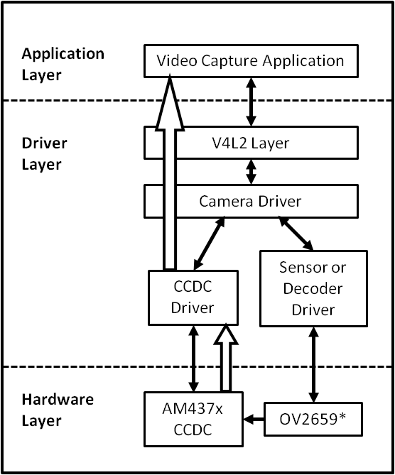
Capture Driver Component Overview
- Camera Applications
- Camera applications refer to any application that accesses the device node that is served by the Camera Driver. These applications are not in the scope of this design. They are here to present the environment in which the Camera Driver is used.
- V4L2 Subsystem
- The Linux V4L2 subsystem is used as an infrastructure to support the operation of the Camera Driver. Camera applications mainly use the V4L2 API to access the Camera Driver functionality. A Linux V4L2 implementation is used in order to support the standard features that are defined in the V4L2 specification.
- Videobuf2 Library
- This library is part of the V4L2 Layer. It provides helper functions to cleanly manage the video buffers through a video buffer queue object.
- Camera Driver
- The Camera Driver allows capturing video through an external sensor/decoder. It is a V4L2-compliant driver which provide access to the AM437x VPFE hardware feature. This driver conforms to the Linux driver model for power management. The camera driver is registered to the V4L2 layer as a master device driver. Any slave sensor/decoder driver added to the V4L2 layer will be attached to this driver through the new V4L2 sub-device interface layer. The current implementation supports only one slave device.
- Sensor/Decoder Driver
- The Camera Driver is designed to be AM437x VPFE module dependent, but platform and board independent. It is the sensor/decoder driver that manages the board connectivity. A decoder driver must implement the V4L2 sub-device interface. It should register to the V4L2 layer as a sub-device. Changing a sensor/decoder requires implementation of a new driver; it does not require changing the Camera Driver. Each sensor/decoder driver exports a set of IOCTLs to the master device through function pointers.
- CCDC library
- CCDC is a HW block, where it acts as a data input/entry port. It receives data from the sensor/decoder through parallel interface. The CCDC library exports API to configure CCDC module. It is configured by the master driver based on the sensor/decoder attached and desired output from the camera driver.
Source Location
- drivers/media/platform/ti_vpfe/
- AM437x VPFE Driver Sources
Kernel Configuration Options
The driver can be built as a static or dynamic module. When built as a dynamic module the driver is named ti_vpfe.ko.
By default VPFE support is built in to the 3.12 kernel when using omap2plus_defconfig.
$ make menuconfig ARCH=arm
- Select “Device Drivers” from the main menu.
...
...
Kernel Features  --->
Boot options  --->
CPU Power Management  --->
Floating point emulation  --->
Userspace binary formats  --->
Power management options  --->
[*] Networking support  --->
Device Drivers  --->
...
...
- Select “Multimedia support” from the menu and enter it.
...
...
[ ] ARM Versatile Express platform infrastructure
-*- Voltage and Current Regulator Support  --->
<*> Multimedia support  --->
    Graphics support  --->
<*> Sound card support  --->
    HID Devices  --->
[*] USB support  --->
...
...
- Select “V4L platform devices” from the menu.
--- Multimedia support
...
...
[ ]   Media PCI Adapters  ----
[*]   V4L platform devices -->
[ ]   Memory-memory multimedia devices ...
[ ]   Media test drivers  ----
      *** Supported MMC/SDIO adapters ***
< >   Cypress firmware helper routines
      *** Media ancillary drivers (tuners, sensors, i2c, frontends) ***
[ ]   Autoselect ancillary drivers (tuners, sensors, i2c, frontends)
      Encoders, decoders, sensors and other helper chips  --->
      Sensors used on soc_camera driver  ----
...
...
- Select “TI AM437x VPFE video capture driver” from the menu.
--- V4L platform devices
...
...
< > SoC camera support
<*>   TI AM437x VPFE video capture driver
...
...
- Selection of OV2659 Camera Sensor driver -
- Now go back to the Multimedia support level
De-select option Autoselect pertinent encoders/decoders and other helper chips and go inside Encoders/decoders and other helper chips
--- Multimedia support
...
...
[ ]   Autoselect ancillary drivers (tuners, sensors, i2c, frontends)
      Encoders, decoders, sensors and other helper chips  --->
      Sensors used on soc_camera driver  ----
...
...
- Select “OmniVision OV2659 sensor support” from the menu.
    *** Audio decoders, processors and mixers ***
...
...
< > Texas Instruments THS8200 video encoder
    *** Camera sensor devices ***
<*> OmniVision OV2659 sensor support
< > OmniVision OV7640 sensor support
...
...
Building as Loadable Kernel Module
- If you want to build the driver as a module, use <M> instead of <*> during menuconfig while selecting the drivers (as shown above). For more information on loadable modules refer Loadable Module HOWTO
DT Configuration
Example configuration in your board DTS file to enable VPFE instance 0. This an excerpt from the arch/arm/boot/dts/am437x-gp-evm.dts
&am43xx_pinmux {
       pinctrl-names = "default";
       pinctrl-0 = <&clkout2_pin &ddr3_vtt_toggle_default>;
...
...
       vpfe0_pins_default: vpfe0_pins_default {
               pinctrl-single,pins = <
                       0x1B0 (PIN_INPUT_PULLUP | MUX_MODE0)  /* cam0_hd mode 0*/
                       0x1B4 (PIN_INPUT_PULLUP | MUX_MODE0)  /* cam0_vd mode 0*/
                       0x1B8 (PIN_INPUT_PULLUP | MUX_MODE0)  /* cam0_field mode 0*/
                       0x1BC (PIN_INPUT_PULLUP | MUX_MODE0)  /* cam0_wen mode 0*/
                       0x1C0 (PIN_INPUT_PULLUP | MUX_MODE0)  /* cam0_pclk mode 0*/
                       0x1C4 (PIN_INPUT_PULLUP | MUX_MODE0)  /* cam0_data8 mode 0*/
                       0x1C8 (PIN_INPUT_PULLUP | MUX_MODE0)  /* cam0_data9 mode 0*/
                       0x208 (PIN_INPUT_PULLUP | MUX_MODE0)  /* cam0_data0 mode 0*/
                       0x20C (PIN_INPUT_PULLUP | MUX_MODE0)  /* cam0_data1 mode 0*/
                       0x210 (PIN_INPUT_PULLUP | MUX_MODE0)  /* cam0_data2 mode 0*/
                       0x214 (PIN_INPUT_PULLUP | MUX_MODE0)  /* cam0_data3 mode 0*/
                       0x218 (PIN_INPUT_PULLUP | MUX_MODE0)  /* cam0_data4 mode 0*/
                       0x21C (PIN_INPUT_PULLUP | MUX_MODE0)  /* cam0_data5 mode 0*/
                       0x220 (PIN_INPUT_PULLUP | MUX_MODE0)  /* cam0_data6 mode 0*/
                       0x224 (PIN_INPUT_PULLUP | MUX_MODE0)  /* cam0_data7 mode 0*/
               >;
       };


       vpfe0_pins_sleep: vpfe0_pins_sleep {
               pinctrl-single,pins = <
                       0x1B0 (DS0_PULL_UP_DOWN_EN | INPUT_EN | MUX_MODE7)  /* cam0_hd mode 0*/
                       0x1B4 (DS0_PULL_UP_DOWN_EN | INPUT_EN | MUX_MODE7)  /* cam0_vd mode 0*/
                       0x1B8 (DS0_PULL_UP_DOWN_EN | INPUT_EN | MUX_MODE7)  /* cam0_field mode 0*/
                       0x1BC (DS0_PULL_UP_DOWN_EN | INPUT_EN | MUX_MODE7)  /* cam0_wen mode 0*/
                       0x1C0 (DS0_PULL_UP_DOWN_EN | INPUT_EN | MUX_MODE7)  /* cam0_pclk mode 0*/
                       0x1C4 (DS0_PULL_UP_DOWN_EN | INPUT_EN | MUX_MODE7)  /* cam0_data8 mode 0*/
                       0x1C8 (DS0_PULL_UP_DOWN_EN | INPUT_EN | MUX_MODE7)  /* cam0_data9 mode 0*/
                       0x208 (DS0_PULL_UP_DOWN_EN | INPUT_EN | MUX_MODE7)  /* cam0_data0 mode 0*/
                       0x20C (DS0_PULL_UP_DOWN_EN | INPUT_EN | MUX_MODE7)  /* cam0_data1 mode 0*/
                       0x210 (DS0_PULL_UP_DOWN_EN | INPUT_EN | MUX_MODE7)  /* cam0_data2 mode 0*/
                       0x214 (DS0_PULL_UP_DOWN_EN | INPUT_EN | MUX_MODE7)  /* cam0_data3 mode 0*/
                       0x218 (DS0_PULL_UP_DOWN_EN | INPUT_EN | MUX_MODE7)  /* cam0_data4 mode 0*/
                       0x21C (DS0_PULL_UP_DOWN_EN | INPUT_EN | MUX_MODE7)  /* cam0_data5 mode 0*/
                       0x220 (DS0_PULL_UP_DOWN_EN | INPUT_EN | MUX_MODE7)  /* cam0_data6 mode 0*/
                       0x224 (DS0_PULL_UP_DOWN_EN | INPUT_EN | MUX_MODE7)  /* cam0_data7 mode 0*/
               >;
       };
...
...
};
...
...
&i2c1 {
       status = "okay";
       pinctrl-names = "default";
       pinctrl-0 = <&i2c1_pins>;
...
...
       ov2659@30 {
               compatible = "ti,ov2659";
               reg = <0x30>;


               port {
                       ov2659_0: endpoint {
                               remote-endpoint = <&vpfe0_ep>;
                               mclk-frequency = <12000000>;
                       };
               };
       };
};
...
...
&vpfe0 {
       status = "okay";
       pinctrl-names = "default", "sleep";
       pinctrl-0 = <&vpfe0_pins_default>;
       pinctrl-1 = <&vpfe0_pins_sleep>;


       /* Camera port \*/
       port {
               vpfe0_ep: endpoint {
                       remote-endpoint = <&ov2659_0>;
                       if_type = <2>;
                       bus_width = <8>;
                       hdpol = <0>;
                       vdpol = <0>;
               };
       };
};
- remote-endpoint is a reference to the i2c sensor node. This is used during sub-device registration.
- if-type defines the interface type used <0> BT656, <2> RAW.
- bus_width defines the number of data pins actually connected between the camera and the vpfe module. Only 2 values are supported 8 and 10. Pre-Beta boards had 10 data pins connected, Beta (and later) have 8 data pins connected which is a hardware level optimization reducing memory bus bandwidth and eliminating post-processing to compact the captured data.
- hdpol when set to 1 is used to invert the Hsync polarity
- vdpol when set to 1 is used to invert the Vsync polarity
Driver Usage
As seen previously the driver create a /dev/videoX device node when a sub-device is successfully registered. The device node provide access to the driver following a standard V4L2 API.
The driver support the following system calls and V4L2 ioctls:
open(), close(), mmap(), munmap() and ioctl()
| V4L2 ioctls | Definition |
|---|---|
| VIDIOC_REQBUFS | Allocating Memory Buffers |
| VIDIOC_QUERYBUF | Getting Buffer’s Physical Address |
| VIDIOC_QUERYCAP | Query Capabilities |
| VIDIOC_ENUMINPUT | Input Enumeration |
| VIDIOC_S_INPUT | Set Input |
| VIDIOC_G_INPUT | Get Input |
| VIDIOC_ENUMSTD | Standard Enumeration |
| VIDIOC_QUERYSTD | Query Standard |
| VIDIOC_S_STD | Set Standard |
| VIDIOC_G_STD | Get Standard |
| VIDIOC_ENUM_FMT | Format Enumeration |
| VIDIOC_ENUM_FRAMESIZES | Frame Size Enumeration |
| VIDIOC_S_FMT | Set Format |
| VIDIOC_G_FMT | Get Format |
| VIDIOC_TRY_FMT | Try Format |
| VIDIOC_QUERYCTRL | Query Control* |
| VIDIOC_S_CTRL | Set Control* |
| VIDIOC_G_CTRL | Get Control* |
| VIDIOC_QBUF | Queue Buffer |
| VIDIOC_DQBUF | Dequeue Buffer |
| VIDIOC_STREAMON | Stream On |
| VIDIOC_STREAMOFF | Stream Off |
| VIDIOC_CROPCAP | Query Cropping Capabilities+ |
| VIDIOC_S_CROP | Set Crop Parameters+ |
| VIDIOC_G_CROP | Get Current Cropping Parameters+ |
Table: Supported ioctls
There are plenty of generic V4L2 capture applications available:
There is also a media controller sample application which can be used as an example to configured sensor/decoder sub-device:
Debugging
As vpfe driver is based on the V4L2 framework, framework level tracing can be enable as follows:
- echo 3 >/sys/class/video4linux/video1/dev_debug This allows V4L2 ioctl calls to be logged.
- echo 3 > /sys/module/videobuf2_core/parameters/debug This allows VB2 buffers operation to be logged.
In addition vpfe also has specific debug log which can be enabled as follows:
- echo 3 > /sys/module/am437x_vpfe/parameters/debug
3.3.4.4. VIP
Introduction
This page gives a basic description of Video Input Port (VIP) hardware, the Linux kernel driver (ti-vip) and various TI boards which uses VIP. The technical reference manual (TRM) for the SoC in question, and the board documentation give more detailed descriptions.
Release Applicable
This page applies to TI’s v4.4 kernel. Although most of it is also applicable to TI’s v4.1 and v3.14 kernel.
Supported Devices
The VIP IP is only available on the following TI SoCs or SoC families:
- AM5x
- DRA7x
Hardware Architecture
On supported SoCs the Video Input Port (VIP) module is used for video capture from video encoder/decoder and camera sensor.
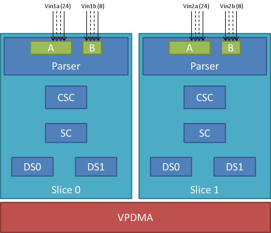
VIP Instance block diagram
VIP instance has two slices each having one 24/16/8 bit port and one 8 bit video port. Each slice has a color space converter block, a scaler block and a pair of down-sampler block. A common VPDMA block is used for writing frames to memory. VIP Parser supports video capture from discrete sync / embedded sync, YUV / RGB format video sources. It calculates the frame size based on the count of clocks in hsyncs(width) and count of hsyncs in vsyncs(height). The complex data path configurability allows to have up to four parallel ports captures from one instance. One port per slice can utilize the inline CSC and/or SC block at a time. VPDMA block has a TI proprietary custom programmable processor. A custom firmware is needed for this custom processor. VPDMA programming is descriptor based. It allows to setup, configure, control, abort DMA transactions from different channels to and from memory. VPDMA needs physically contiguous buffers for capture. It also supports addressing in the TILER space.
SoC Hardware Feature
- AM572x/DRA74x/DRA75x
- VIP1 and VIP2 instance each supporting up to
- Two separate 24-bit video ports for parallel RGB/YUV/RAW (or BT656/1120) data, up to 165 MHz
- Two separate 8-bit video ports for YUV/RAW (or BT656) data, up to 165 MHz
- VIP3 instance supporting up to
- Two separate 16-bit video ports for parallel RGB/YUV/RAW (or BT656/1120) data, up to 165 MHz
- VIP1 and VIP2 instance each supporting up to
- AM571x/DRA72x
- VIP1 instance supporting up to
- Two separate 24-bit video ports for parallel RGB/YUV/RAW (or BT656/1120) data, up to 165 MHz
- Two separate 8-bit video ports for YUV/RAW (or BT656) data, up to 165 MHz
- VIP1 instance supporting up to
Driver Architecture
Linux kernel driver for the VIP is implemented as per the V4L2 standard for capture devices. VIP driver is responsible only for the programming of the VIP device. For programming external video devices, we need a V4L2 subdevice driver which is used in conjunction with the V4L2 driver. It also uses some of the helper kernel libraries videobuf2 (VB2) for common buffer operations, queue management and memory management.
- Linux Media Subsystem Documentation
- Video for Linux API
- V4L2 videobuf2 functions and data structures
- V4L2 sub-devices
V4L2 endpoint device tree bindings
Different camera / video sources have different configuration parameters when interfacing with the VIP video ports. Common interfacing properties like Hsync, Vsync, Pclk polarities can be different across different devices. V4L2 endpoint allows to describe these as part of device tree definition. This makes the VIP driver generic enough to have no dependency on the camera device. It also provides the flexibility to work with new cameras by doing simple device tree modifications.
Following is an example showcasing the DT entries of VIP device node and its usage when interfacing different video sources.
| VIP device definition | Camera device definition |
|---|---|
vip1 {
    #address-cells = <1>;
    #size-cells = <0>;
    status = "okay";
    ports {
        vin1a: port@0 {
             reg = <0>;
             #address-cells = <1>;

             #size-cells = <0>;
             status = "okay";
             endpoint@0 {
                 remote-endpoint = <&cam1>;

             };
        };
        ...
        vin2a: port@2 {
             ...
             reg = <2>;
        };
        ...
    };
};
|
ov10633@37 {
    compatible = "ovti,ov10633";
    reg = <0x37>
    ...
    port {
        cam1: endpoint {
            remote-endpoint = <&vin1a>;
            hsync-active = <1>;
            vsync-active = <1>;
            pclk-sample = <0>;

        };
    };
};
|
V4L2 asynchronous subdevice registration
Each camera device that VIP driver communicates to is modelled as a V4L2 subdevice. In the probe sequence, VIP and camera drivers are probed at different time. V4L2 async subdevice binding helps to bind the VIP device and the camera device together. VIP driver looks for the camera entries in the endpoints and registers (v4l2_async_notifier_register) a callback if any of the requested devices become available. vip_async_bound implements the priority based binding which allows to have multiple cameras muxed against same video port. The device tree order determines which of these gets picked up by the driver. Note that the V4L2 g/s_input ioctls are not supported, userspace won’t be able to select specific camera with these ioctls.
Of course the target subdevice driver also needs to support the asynchronous registration framework. On top of this the subdevice driver must implements the following ioctls for the handshake with the VIP driver to work properly:
- get_fmt()
- set_fmt()
- enum_mbus_code()
- enum_frame_sizes()
- s_stream()
Driver Features
Note: this is not a comprehensive list of features supported/not supported.
Supported Features
- VIP input Pixel formats
- Sub device is expected to support one of the below format. Only YUV422 interleaved format arranged as UYVY is supported in YUV mode. This restrictions in pixel arrangements is to take care of silicon errata i839 guidelines.
- The data formats mentioned in parenthesis in below table is in
V4L2 Media Bus Format.
- For instance, a format where pixels are encoded as 8-bit YUV values downsampled to 4:2:2 and transferred as 2 8-bit bus samples per pixel in the U, Y, V, Y order is named as MEDIA_BUS_FMT_UYVY8_2X8.
- The data bus width can be 8 bit or 16 bit wide when capturing in
UYVY mode.
- Default bus width configuration is 8 bit. When using 16 bit wide bus, specify the bus width in dts file as bus-width = <16>;
| YUV | RGB | RAW Bayer 8-bit |
|---|---|---|
| UYVY (UVYV8_2x8) | RGB24 (RGB888_1X24) | BGGR8 (SBGGR8_1X8) |
| RGB32 (ARGB8888_1X32) | GBRG8 (SGBRG8_1X8) | |
| GRBG8 (SGRBG8_1X8) | ||
| RGGB8 (SRGGB8_1X8) |
Table: Supported Input Pixel Format in FOURCC and V4L2 MEDIA_BUS_FMT
- Supported VIP output pixel formats
- Runtime pixel format availability is based on the sub-device capability. Use yavta –enum-formats /dev/video1 to get an accurate list.
| YUV | RGB | RAW Bayer 8-bit |
|---|---|---|
| NV12 | RGB3 | BA81 |
| YUYV | BGR3 | GBRG |
| UYVY | RGB4 | GRBG |
| VYUY | BGR4 | RGGB |
| YVYU |
Table: Supported Output Pixel Format
- Scaling (only available with YUV format)
- Down-scaling only (will use the closest native resolution larger than the desired frame size)
- Down-scaling ratio limitations -
- Horizontal - up to 1/8th
- Vertical - up to 3/16
- Color Space Conversion
- YUV to RGB (tested)
- RGB to YUV (untested)
- V4L2 single-planar buffers and interface
- Supports MMAP buffers (allocated by kernel from global CMA pool) and also allows to export them as DMABUF
- Supports DMABUF import (Reusing buffers from other drivers)
- Discrete Sync capture
- Embedded Sync capture in 8-bit mode
- Multi-channel capture when using embedded sync
Unsupported Features/Limitations By VIP Driver
- Media Controller Framework
- Cropping/Selection ioctls
- TILER memory space
- 16 bit embedded capture
- 16 bit RAW capture
- YUV444 Input format
- YUV444 mode is similar to RGB24 mode. Driver can be modified to enable YUV44 mode by referring to the RGB24 settings in vip.c file
- Input format capture for YUV422 mode in arrangements other than UYVY
- Refer to the settings of Raw Bayer input format in vip.c file to enable other YUV input mode capture
- Maximum capture resolution restricted to 2048x1536
- HSYNC and Discrete Basic Mode set as 1 are hard coded in the driver and not controlled through dts entries. VIP driver register settings will need changes if the signals used for capture are DE (ACTVID) and/or Discrete Basic Mode set as 0.
Hardware Limitations
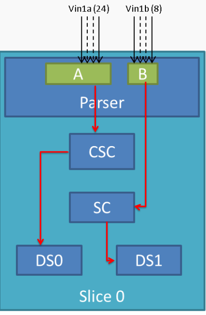
VIP Slice
- CSC, SC and/or DS processing in discrete sync mode is supported only
for following combination -
- Input as RGB or UYVY format and output in supported YUV format
- CSC, SC and/or DS processing is not supported for embedded sync input in multiplexed source mode
- CSC and SC can not be used simultaneously by port A and port B of a Slice. For example, if port A is using CSC, then port B can only use SC but not CSC
- Maximum input resolution when using SC is 2047x2047 pixels (irrespective of pixel size).
- Maximum capture width when not using scaling is 8K bytes. This
translates to maximum frame width of -
- 4K when capturing in YUV422 mode (2 bytes/pixel)
- 2.2K when capturing in RGB24 mode (3 bytes/pixel)
- 8K when capturing as Raw Bayer 8-bit or other format treated as 1 bytes/pixel
- No restrictions on height of capture video
Driver Configuration
Kernel Configuration Options
ti-vip supports building both as built-in or as a module.
ti-vip can be found under “Device Drivers/Multimedia support/V4L platform devices” in the kernel menuconfig. You need to enable V4L2 (CONFIG_MEDIA_SUPPORT, CONFIG_MEDIA_CAMERA_SUPPORT) and then enable V4L platform driver (CONFIG_V4L_PLATFORM_DRIVERS) before you can enable ti-vip (CONFIG_VIDEO_TI_VIP).
Driver Usage
Loading ti-vip
If built as a module, you need to load all the v4l2-common, videobuf2-core and videobuf2-dma-contig modules before ti-vip will start.
Using ti-vip
When ti-vip is enabled, the capture device will appear as /dev/videoX. Standard V4L2 user space applications can be used as long as the capability of the application matches.
- dmabuftest example Use VIP to capture a 1280x800 YUYV video stream and display it on an HDMI display using DMABUF buffers.
dmabuftest -s 36:1920x1080 -c 1280x800@YUYV -d /dev/video1
- yavta example Capture 800x600 YUYV video stream to file.
yavta -c60 -fYUYV -Fvout_800x600_yuyv.yuv -s800x600 /dev/video1
dmabuftest can be found from:
https://git.ti.com/glsdk/omapdrmtest
yavta can be found from:
http://git.ideasonboard.org/yavta.git
Debugging
As ti-vip driver is based on the V4L2 framework, framework level tracing can be enable as follows:
- echo 3 >/sys/class/video4linux/video1/dev_debug This allows V4L2 ioctl calls to be logged.
- echo 3 > /sys/module/videobuf2_core/parameters/debug This allows VB2 buffers operation to be logged.
In addition ti-vip also has specific debug log which can be enabled as follows:
- echo 3 > /sys/module/ti_vip/parameters/debug
Troubleshooting common capture problem
Bootup/Probe checks
First thing to look for is if the video devices are created or not; Check the bootlog for prints in the kernel bootlog.
Check device probe status
dmesg | grep ov1063x
dmesg | grep video
Depending on the camera connected, the following prints can confirm the probe being successful.
| Bootlog print | Result |
|---|---|
| ov1063x 1-0037: ov1063x Product ID a6 Manufacturer ID 33 | Onboard camera probe success |
| ov1063x X-00XX: Failed writing register 0x0103! | Camera not connected |
No video captured
When the capture application is launched, it is expected to start video capture and display frames on to display. Sometimes, no video is not displayed on the screen. To identify this being an issue with capture, simple test can be done. Each VIP slice has a dedicated interrupt line. If the capture is successful, the interrupt count should increase periodically.
Check interrupts to confirm capture failure
cat /proc/interrupts | grep vip
362:        941          0       GIC 102  vip1-s0
363:        183          0       GIC 101  vip1-s1
364:        241          0       GIC 100  vip2-s0
365:          0          0       GIC  99  vip2-s1
366:         46          0       GIC  98  vip3-s0
367:          2          0       GIC  97  vip3-s1
In the above example, one can conclude that
- Capture from Vin1, Vin2, Vin3, Vin5 is working fine.
- Vin4(vip2-s1) capture was never attempted.
- Vin6(vip3-s1) capture is failing (Note that first two interrupts occur even if the camera isn’t connected. Refer VPDMA fifo)
Note that the IRQs are shared for different ports of same slice. This means, vip1-s0 line will carry interrupts from both vin1a and vin1b. This test can be used when only one of the port is in use.
VIP Parser is not able to detect the video
| Video Port | Parser size register | Parser config register |
|---|---|---|
| vin1a | 0x48975530 | 0x48975504 |
| vin1b | 0x48975570 | 0x4897550C |
| vin2a | 0x48975A30 | 0x48975A04 |
| vin2b | 0x48975A70 | 0x48975A0C |
| vin3a | 0x48995530 | 0x48995504 |
| vin3b | 0x48995570 | 0x4899550C |
| vin4a | 0x48995A30 | 0x48995A04 |
| vin4b | 0x48995A70 | 0x48995A0C |
| vin5a | 0x489B5530 | 0x489B5504 |
| vin6a | 0x489B5A30 | 0x489B5A0C |
Invalid parser configuration
Depending on the camera used, certain parameters of the video port needs to be configured correctly. Device tree definition (endpoint nodes) is used for specifying these parameters.
| Usecase | Required parameters |
|---|---|
| Parallel port | Bus width (8/16bit for YUV, 24bit for RGB) |
| Descrete sync | hsync, vsync, pclk polarities |
| Embedded sync | Multiplexing method, channel numbers |
To check if the correct parameters are being passed or not, procfs can be used for checking values of some of the properties on target.
Using procfs to read DT params
cat /proc/device-tree/ocp/i2c@480720000/ov10635@37/compatible
hexdump -b /proc/device-tree/ocp/i2c@480720000/ov10635@37/port/endpoint@0/pclk-sample
hexdump -b /proc/device-tree/ocp/i2c@480720000/ov10635@37/port/endpoint@0/bus-width
hexdump -b /proc/device-tree/ocp/i2c@480720000/ov10635@37/port/endpoint@0/channels
Note that some of the integer properties are not printable in ASCII format. Using hexdump gives readability to read integer values from device tree.
Camera isn’t started, pclk, syncs are dead
Video is being captured but image is pixelated or distorted
FAQ
Can VIP be used as high speed interface to bring any data in?
VIP can be used as high speed interface to bring any data as is (without any modifications) into the device. Following points to keep in mind –
- Data should be sent in discrete sync mode.
- No other VIP internal processing blocks like color space conversion, scaling or chroma format conversion should be used.
- Refer to Driver_Features section if there is need to bring data in resolution greater than the one supported by driver.
- If the cropping feature is disabled in VIP parser due to the need for capturing larger resolution and if interested in capturing last frame (that could be only frame), FPGA need to send additional VSYNC signal else the last frame will not get transferred to DDR.
- Add vip_fmt entry in the vip_formats table inside drivers/media/platform/ti-vpe/vip.c per sub-device driver need for ”.fourcc”, ”.code” and ”.colorspace”. Keep ”.coplanar” as 0. Refer to the entries of VPDMA_DATA_FMT_RAW8 in drivers/media/platform/ti-vpe/vpdma.c file for “vpdma_fmt” settings when using VIP slice in 8 bit port mode. Refer to the VPDMA_DATA_FMT_RAW16 format settings for 16 bit mode. Note that VIP driver supports only 8 bit RAW mode. Enabling 16 bit RAW mode capture needs minor driver modifications. If custom entries are not needed, then any of the raw format entries can be used. In that case, sensor driver will need to configure media bus format as ”.code” settings as shown in the vip_fmt.
static struct vip_fmt vip_formats[VIP_MAX_ACTIVE_FMT] = {
    {
        .fourcc        = V4L2_PIX_FMT_SBGGR8,
        .code      = MEDIA_BUS_FMT_SBGGR8_1X8,
        .colorspace    = V4L2_COLORSPACE_SMPTE170M,
        .coplanar  = 0,
        .vpdma_fmt = { &vpdma_raw_fmts[VPDMA_DATA_FMT_RAW8],
                  },
    },

const struct vpdma_data_format vpdma_raw_fmts[] = {
    [VPDMA_DATA_FMT_RAW8] = {
        .type      = VPDMA_DATA_FMT_TYPE_YUV,
        .data_type = DATA_TYPE_CBY422,
        .depth     = 8,
    },
What’s the maximum frame rate possible for W*H resolution using VIP?
As mentioned in Hardware_Architecture section, each slice in VIP instance has one 24/16/8 bit port through which data can come in. Each video port can be clocked up to 165 MHz. Assuming 27% left spare for horizontal and vertical blanking, roughly 120 MHz left for actual data. If VIP Slice is configured in 8 bit port mode, then 1 bytes can be brought in per clock cycle. In 8 bit port mode and with 120 MHz clock for data capture, maximum possible capture rate is 120 Mbytes/sec, in 16 bit port mode it will be 240 Mbytes/sec and in 24 bit port mode it will be 360 Mbytes/sec. Now for X*Y resolution, maximum possible frame rate can be calculated using following formula –
FPS = 120 * 1000000 * port_mode/(frame_resolution * num_bytes_per_pixel)
In above formula -
- port_mode can take value of 1 for 8 bit, 2 for 16 bit and 3 for 24 bit port mode configuration.
- Frame_resolution is product of width and height of frame.
- num_bytes_per_pixel is number of bytes per pixel. For example, if capturing in YUYV format it’s value is 2, when capturing in RGB24 format, it’s value is 3.
What is the maximum frame resolution that can be captured using VIP?
Refer to Hardware_Limitations section to understand maximum possible resolution supported by VIP IP. Refer to Unsupported_Features/Limitations section to understand the resolution supported by VIP driver. Driver changes will be needed to capture the resolution beyond the one supported by the driver but within VIP IP limits. Below are suggested modifications inside driver. There may be more changes needed.
- Change MAX_W and MAX_H in vip.c file per the desired capture resolution.
- Disable hardware enabled cropping feature inside the driver if the
desired resolution width is greater than 4K pixels (not bytes) and/or
height is greater than 4K lines.
- To disable cropping, comment the function call to vip_set_crop_parser() function inside vip_setup_parser() function defined in drivers/media/platform/ti-vpe/vip.c file
Why I am not seeing any interrupt generated from the sensor?
Not getting any interrupts usually means the module is not receiving/detecting video data. To proceed with debugging, probe the pclk, vysnc and hsync signal at the connector. If they look as what you are expecting, then verify the pinmux.
How do I capture 10-bit or 12-bit YUV data?
VIP can capture data in 8, 16 or 24 bus-width size. Configure VIP for 16 bit bus-width size in order to capture pixel of 10-bit or 12-bit size. This includes dts file configuration and pin-mux configuration. Connect the pixel size data lanes from the sensor board to VIP input port. Ground or tie to VDD remaining unused pins. VIP will receive the 10-bit/12-bit data in 16-bit container in memory with 6/4 LSb or MSb bit always being low or high based on how those unused bits are tied. Note that when capturing 10-bit/12-bit data in 16 bit container, you can not use any of the VIP internal processing module like scaling, format conversion etc.
In dts file, specify the bus-width field as 16
bus-width = <16>; /* Used data lines */
TI Board Specific Information
None at this time.
3.3.4.5. Crypto
Introduction
The Crypto API Driver is a set of Linux drivers that provide access to the hardware cryptographic accelerators available on AM335x/AM437x/AM57x/DRA7 devices. These drivers are available built-in in the kernel in the current SDK release.
Following are the Hardware accelerators supported on the following devices:
* AM335X     : MD5, SHA1, SHA224, SHA256, AES, DES
* AM437X     : MD5, SHA1, SAH224, SHA256, SHA384, SHA512, AES, DES, DES3DES
* AM57x/DRA7 : AES, DES, DES3DES
Building the Driver
For devices with available cryptographic hardware accelerators, a Linux driver and additionally an Cryptodev (or OCF on AMSDK v6.0 or older) kernel module (for OpenSSL) is needed to access them. Other devices use the pure software implementation of OpenSSL for the crypto demos.
AM335x, AM43xx - AES, DES, SHA/MD5 Drivers
Starting with AMSDK 5.05.00.00, the driver is completely integrated into the kernel source. The pre-built kernel that comes with the SDK already has the AES, DES and SHA/MD5 drivers built-in to the kernel. The kernel configuration has already been set up in the SDK and no further configuration is needed for the drivers to be built-in to the kernel. The configuration of the random number generator does require an extra step and this is detailed in the next section.
For reference, the configuration details are shown below. The configuration of the AES, DES and SHA/MD5 driver is done under the Hardware crypto devices sub-menu of the Cryptographic API menu in the kernel configuration.
--- Cryptographic API
    [*] Hardware crypto devices --->
        --- Hardware crypto devices
            <*> Support for OMAP MD5/SHA1/SHA2 hw accelerator
            <*> Support for OMAP AES hw engine
            <*> Support for OMAP DES3DES hw engine
Messages printed during bootup will indicate that initialization of the crypto modules has taken place.
[    2.120565] omap-sham 53100000.sham: hw accel on OMAP rev 4.3
[    2.160584] mmc1: BKOPS_EN bit is not set
[    2.173466] omap-aes 53500000.aes: OMAP AES hw accel rev: 3.2
[    2.180241] edma-dma-engine edma-dma-engine.0: allocated channel for 0:5
[    2.187808] edma-dma-engine edma-dma-engine.0: allocated channel for 0:6
Build the Cryptodev kernel module using SDK
For using OpenSSL to access the Crypto Hardware Accelerator Drivers above, the Cryptodev is required (can be built as module). The framework is not officially in the kernel and was ported to Linux under the name “cryptodev”.
Using Cryptographic Hardware Accelerators
Using the TRNG Hardware Accelerator
The pre built kernel that come with the SDK already has the TRNG driver built into the kernel. No further configuration is required.
For reference, the configuration details are shown below.
In the configuration menu, scroll down to Device Drivers and hit enter. Now scroll to Character devices and hit enter.
Device Drivers --->
   Character devices --->
       < > Hardware Random Number Generator Core support
           < > OMAP Random Number Generator support
[ 1.660514] omap_rng 48310000.rng: OMAP Random Number Generator ver. 20
root@am335x-evm:~# ls -l /dev/hwrng
crw------- 1 root root 10, 183 Jan 1 2000 /dev/hwrng
root@am335x-evm:~#
root@am335x-evm:~# cat /dev/hwrng | od -x
0000000 b2bd ae08 4477 be48 4836 bf64 5d92 01c9
0000020 0cb6 7ac5 16f9 8616 a483 7dfd 6bf4 3aa5
0000040 d693 db24 d917 5ee7 feb7 34c3 34e9 e7a5
0000060 36b7 ea85 fc17 0e66 555c 0934 7a0c 4c69
0000100 523b 9f21 1546 fddb d58b e5ed 142a 6712
0000120 8d76 8f80 a6d2 30d8 d107 32bc 7f45 f997
0000140 9d5d 0d0c f1f0 64f9 a77f 408f b0c1 f5a0
0000160 39c6 f0ae 4b59 1a76 84a7 a364 8964 f557
root@am335x-evm:~#
Support tools for the hardware random number generator can be loaded from rng-tools on Sourceforge. The latest version at the time of this write-up is version 3.0, dated 2010-07-04.
1. We’re still in the Linux-devkit environment. Download the file rng-tools-3.tar.gz, and untar in a suitable location.
2. Change to the directory that contains the rng-tools distribution, and configure the package:
host $ ./configure --prefix=/home/user/targetfs/TI814x-targetfs_5_03_01/usr \
 --exec-prefix=/home/user/targetfs/TI814x-targetfs_5_03_01/usr \
 --host --target=arm-linux
3. Next make the rngd and rngtest executables.
host $ make
4. Install the generated executables in the target filesystem.
5. Test the random number generator on the target.
root@am335x-evm:~# cat /dev/hwrng | rngtest -c 1000
rngtest 3
Copyright (c) 2004 by Henrique de Moraes Holschuh
This is free software; see the source for copying conditions.  There is NO warranty; not even for MERCHANTABILITY or FITNESS FOR A PARTICULAR PURPOSE.

rngtest: starting FIPS tests...
rngtest: bits received from input: 20000032
rngtest: FIPS 140-2 successes: 999
rngtest: FIPS 140-2 failures: 1
rngtest: FIPS 140-2(2001-10-10) Monobit: 0
rngtest: FIPS 140-2(2001-10-10) Poker: 0
rngtest: FIPS 140-2(2001-10-10) Runs: 1
rngtest: FIPS 140-2(2001-10-10) Long run: 0
rngtest: FIPS 140-2(2001-10-10) Continuous run: 0
rngtest: input channel speed: (min=788.218; avg=4070.983; max=2790178.571)Kibits/s
rngtest: FIPS tests speed: (min=846.755; avg=15388.376; max=21920.595)Kibits/s
rngtest: Program run time: 6072670 microseconds
Note that the results may be slightly different on your system, since, after all, we’re dealing with a random number generator. Any appreciable number of errors typically indicates a bad random number generator.
If you’re satisfied the random number generator is working correctly, you can use rngd (the random number generator daemon) to feed the /dev/random entropy pool.
AES, DES, SHA Hardware Accelerators using Cryptodev
The device drivers for AES, DES and SHA/MD5 hardware acceleration is configured and built into the kernel by default. No other special setup is needed for OpenSSL to access the crypto modules.
First, the kernel from the SDK must be configured and built according to the SDK User’s Guide.
The General Purpose (GP) EVMs on TI SoCs allows access to built in cryptographic accelerators. Inorder to use these drivers from OpenSSL, the drivers on their own have no contact with userspace. For this, a special driver is available which abstracts the access to these accelerators through Cryprodev module.
The demo application under the crypto menu of Matrix will load and use the Cryptodev driver kernel modules automatically to perform hardware accelerated crypto functions. The process of manually loading the kernel modules and using the driver is explained below.
Cryptodev is itself a special device driver which provides a general interface for higher level applications such as OpenSSL to access hardware accelerators.
The filesystem which comes with the SDK comes built with the Cryptodev kernel modules and the TI driver which directly accesses the hardware accelerators is built into the kernel.
From the target boards perspective the drivers are located in the following directories:
/lib/modules/`uname -r`/extra/cryptodev.ko
To use the drivers they must first be installed. Use the modprobe command to install the drivers. The following log shows the commands used to install the modules and query the system for the state of all system modules.
root@am335x-evm:~# lsmod
Module                  Size  Used by
cryptodev              11962  0
root@am335x-evm:~#
After the modules are installed, OpenSSL commands may be executed which take advantage of the hardware accelerators through the Cryptodev driver. The following example demonstrates the OpenSSL built-in speed test to demonstrate performance. The addition of the parameter -engine cryptodev tells OpenSSL to use the Cryptodev driver if it exists.
root@am335x-evm:~# openssl speed -evp aes-128-cbc -engine cryptodev
engine "cryptodev" set.
Doing aes-128-cbc for 3s on 16 size blocks: 108107 aes-128-cbc's in 0.16s
Doing aes-128-cbc for 3s on 64 size blocks: 103730 aes-128-cbc's in 0.20s
Doing aes-128-cbc for 3s on 256 size blocks: 15181 aes-128-cbc's in 0.03s
Doing aes-128-cbc for 3s on 1024 size blocks: 15879 aes-128-cbc's in 0.03s
Doing aes-128-cbc for 3s on 8192 size blocks: 4879 aes-128-cbc's in 0.02s
OpenSSL 1.0.0b 16 Nov 2010
built on: Thu Jan 20 10:23:44 CST 2011
options:bn(64,32) rc4(ptr,int) des(idx,risc1,2,long) aes(partial) idea(int) blowfish(idx)
compiler: arm-none-linux-gnueabi-gcc -march=armv7-a -mtune=cortex-a8 -mfpu=neon -mfloat-abi=softfp -mthumb-interwork -mno-thumb -fPS
The 'numbers' are in 1000s of bytes per second processed.
type 16 bytes 64 bytes 256 bytes 1024 bytes 8192 bytes
aes-128-cbc 10810.70k 33193.60k 129544.53k 542003.20k 1998438.40k
root@am335x-evm:~#
root@am335x-evm:~#
root@am335x-evm:~#
Using the Linux time -v function gives more information about CPU usage during the test.
root@am335x-evm:~# time -v openssl speed -evp aes-128-cbc -engine cryptodev
engine "cryptodev" set.
Doing aes-128-cbc for 3s on 16 size blocks: 108799 aes-128-cbc's in 0.17s
Doing aes-128-cbc for 3s on 64 size blocks: 102699 aes-128-cbc's in 0.18s
Doing aes-128-cbc for 3s on 256 size blocks: 16166 aes-128-cbc's in 0.03s
Doing aes-128-cbc for 3s on 1024 size blocks: 15080 aes-128-cbc's in 0.03s
Doing aes-128-cbc for 3s on 8192 size blocks: 4838 aes-128-cbc's in 0.03s
OpenSSL 1.0.0b 16 Nov 2010
built on: Thu Jan 20 10:23:44 CST 2011
options:bn(64,32) rc4(ptr,int) des(idx,risc1,2,long) aes(partial) idea(int) blowfish(idx)
compiler: arm-none-linux-gnueabi-gcc -march=armv7-a -mtune=cortex-a8 -mfpu=neon -mfloat-abi=softfp -mthumb-interwork -mno-thumb -fPS
The 'numbers' are in 1000s of bytes per second processed.
type 16 bytes 64 bytes 256 bytes 1024 bytes 8192 bytes
aes-128-cbc 10239.91k 36515.20k 137949.87k 514730.67k 1321096.53k
Command being timed: "openssl speed -evp aes-128-cbc -engine cryptodev"
User time (seconds): 0.46
System time (seconds): 5.89
Percent of CPU this job got: 42%
Elapsed (wall clock) time (h:mm:ss or m:ss): 0m 15.06s
Average shared text size (kbytes): 0
Average unshared data size (kbytes): 0
Average stack size (kbytes): 0
Average total size (kbytes): 0
Maximum resident set size (kbytes): 7104
Average resident set size (kbytes): 0
Major (requiring I/O) page faults: 0
Minor (reclaiming a frame) page faults: 479
Voluntary context switches: 36143
Involuntary context switches: 211570
Swaps: 0
File system inputs: 0
File system outputs: 0
Socket messages sent: 0
Socket messages received: 0
Signals delivered: 0
Page size (bytes): 4096
Exit status: 0
When the cryptodev driver is removed, OpenSSL reverts to the software implementation of the crypto algorithm. The performance using the software only implementation can be compared to the previous test.
root@am335x-evm:~# modprobe -r cryptodev
root@am335x-evm:~# time -v openssl speed -evp aes-128-cbc
Doing aes-128-cbc for 3s on 16 size blocks: 697674 aes-128-cbc's in 2.99s
Doing aes-128-cbc for 3s on 64 size blocks: 187556 aes-128-cbc's in 3.00s
Doing aes-128-cbc for 3s on 256 size blocks: 47922 aes-128-cbc's in 3.00s
Doing aes-128-cbc for 3s on 1024 size blocks: 12049 aes-128-cbc's in 3.00s
Doing aes-128-cbc for 3s on 8192 size blocks: 1509 aes-128-cbc's in 3.00s
OpenSSL 1.0.0b 16 Nov 2010
built on: Thu Jan 20 10:23:44 CST 2011
options:bn(64,32) rc4(ptr,int) des(idx,risc1,2,long) aes(partial) idea(int) blowfish(idx)
compiler: arm-none-linux-gnueabi-gcc -march=armv7-a -mtune=cortex-a8 -mfpu=neon -mfloat-abi=softfp -mthumb-interwork -mno-thumb -fPS
The 'numbers' are in 1000s of bytes per second processed.
type 16 bytes 64 bytes 256 bytes 1024 bytes 8192 bytes
aes-128-cbc 3733.37k 4001.19k 4089.34k 4112.73k 4120.58k
Command being timed: "openssl speed -evp aes-128-cbc"
User time (seconds): 15.03
System time (seconds): 0.00
Percent of CPU this job got: 99%
Elapsed (wall clock) time (h:mm:ss or m:ss): 0m 15.07s
Average shared text size (kbytes): 0
Average unshared data size (kbytes): 0
Average stack size (kbytes): 0
Average total size (kbytes): 0
Maximum resident set size (kbytes): 7216
Average resident set size (kbytes): 0
Major (requiring I/O) page faults: 1
Minor (reclaiming a frame) page faults: 484
Voluntary context switches: 13
Involuntary context switches: 35
Swaps: 0
File system inputs: 0
File system outputs: 0
Socket messages sent: 0
Socket messages received: 0
Signals delivered: 0
Page size (bytes): 4096
Exit status: 0
3.3.4.6. MCAN
Introduction
The Controller Area Network is a serial communications protocol which efficiently supports distributed real-time control with a high level of security. The MCAN module supports bitrates up to 5 Mbit/s and is compliant to the ISO 11898-1:2015. The core IP within M_CAN is provided by Bosch.
This wiki page provides usage information of M_CAN Linux driver.
Setup Details
TI board List
| SoC | Board | Number of Instances | Connection Type | Enabled by default |
|---|---|---|---|---|
| Dra76x | EVM | 1 | Header | Yes |
Table: Boards M_CAN Driver is Validated on
Connection Configuration
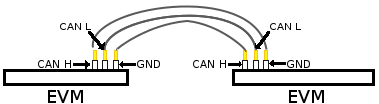
|
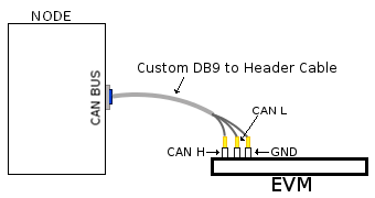
|
| Header to Header | Header to DB9 |
Table: Various DCAN EVM Connection Configuration
Equipment
Female DB9 Cable
For boards exposing M_CAN using male DB9 connectors, a female connector is required. The other side can be male or female depending on the other CAN device the user connects to.
Jumper Wires
For boards where the CAN pins are broken out via a header, female jumper cables will be ideal for connection. The CAN pins will be CAN H (typically pin 1 of the header), GND (middle pin of the header) and CAN L (lowest pin on the header). The pinout in the header might vary across different boards and users must consult the board’s schematic to verify this.

Custom DB9 to Header Cable
Typically CAN devices use a DB9 connection therefore for boards whose CAN pins are broken out via a header it is helpful to create a header to DB9 connector cable. This custom cable is simple to make. Either a male or female DB9 connector (not cable) must be obtained along with three female jumper wires.
Snip one end of each of the jumper wires and expose some of the wiring. Now solder each of the exposed wires to pin 7 (CAN H), pin 2 (CAN L) and pin 3 (GND). Make sure your soldering on the side of the DB9 that has the metal lip meant to push some of the exposed wire into and soldering to the correct pins correctly. Use the below diagram as a reference.

|
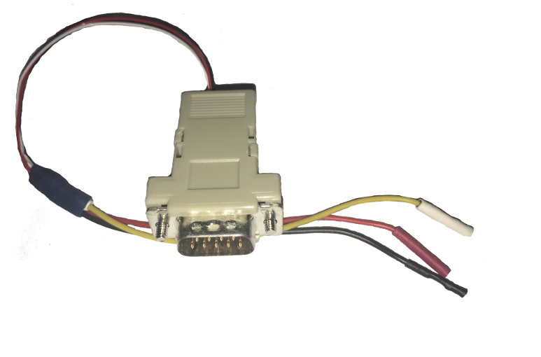
|
| Wiring Diagram | Example of completed cable. |
CAN Utilities
There may be other userspace applications that can be used to interact with the CAN bus but the SDK supports using Canutils which is already included in the sdk filesystem.
Note
These instructions are for can0 (first and perhaps only CAN instance enabled). If the board has multiple CAN instances enabled then they can be referenced by incrementing the CAN instance number. For example 2 CAN instances will have can0 and can1.
Quick Steps
Initialize CAN Bus
- Set bitrate
$ ip link set can0 type can bitrate 1000000
- CAN-FD mode
$ ip link set can0 type can bitrate 1000000 fd on
- CAN-FD mode with bitrate switching
$ ip link set can0 type can bitrate 1000000 dbitrate 4000000 fd on
Start CAN Bus
- Device bring up
Bring up the device using the command:
$ ip link set can0 up
Transfer Packets
Cansend
Used to generate a specific can frame. The syntax for cansend is as follows:
<can_id>#{R|data}          for CAN 2.0 frames
<can_id>##<flags>{data}    for CAN FD frames
Some examples:
- Send CAN 2.0 frame
$ cansend can0 123#DEADBEEF
- Send CAN FD frame
$ cansend can0 113##2AAAAAAAA
- Send CAN FD frame with BRS
$ cansend can0 143##1AAAAAAAAA
Cangen
Used to generate frames at equal intervals. The syntax for cangen is as follows:
cangen [options] <CAN interface>
Some examples:
- Full load test with polling, 10 ms timeout
$ cangen can0 -g 0 -p 10 -x
b. fixed CAN ID and length, inc. data, canfd frames with bitrate switching
$ cangen vcan0 -g 4 -I 42A -L 1 -D i -v -v -f -b
Candump
Candump is used to display received frames.
candump [options] <CAN interface>
Example:
$ candump can0
Note: Use Ctrl-C to terminate candump
Further options for all canutils commands are available at https://git.pengutronix.de/cgit/tools/canutils
Stop CAN Bus
Stop the can bus by:
$ ip link set can0 down
3.3.4.7. DCAN
Introduction
The Controller Area Network is a serial communications protocol which efficiently supports distributed real-time control with a high level of security. The DCAN module supports bitrates up to 1 Mbit/s and is compliant to the CAN 2.0B protocol specification. The core IP within DCAN is provided by Bosch.
This wiki page provides usage information of DCAN Linux driver.
Acronyms & definitions
| Acronym | Definition |
|---|---|
| CAN | Controller Area Network |
| BTL | Bit timing logic |
| DLC | Data Length Code |
| MO | Message Object |
| LEC | Last Error Code |
| FSM | Finite State Machine |
| CRC | Cyclic Redundancy Check |
Table: DCAN Driver: Acronyms
Setup Details
EVM List
| SoC | EVM | Number of Instances | Connection Type | Enabled by default |
|---|---|---|---|---|
| AM335x | General Purpose EVM | 1 | DB9 | No |
| AM437x | General Purpose EVM | 2 | DB9 | Yes |
| 66AK2Gx | General Purpose EVM | 2 | DB9 | Yes |
| AM571x | Industrial Development Kit | 1 | Header | Yes |
| DRA74x | Evaluation Module | 1 | Header | Yes |
| DRA72x | Evaluation Module | 1 | Header | Yes |
Table: EVMs DCAN Driver is Validated on
NOTE On AM335x GP EVM CAN does not work by default. The evm must have its “Profile Switch” set to 1 to enable CAN support.
Hardware/Software Changes to Enable CAN Support
AM335x General Purpose EVM
Most TI boards by default will allow the user to use CAN without any changes. The boards that do require modifications to be enabled for CAN to work will be listed below.
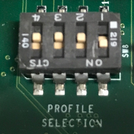
|
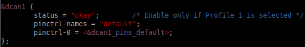
|
| enable) | disabled to okay |
Table: AM335x Hardware and Software modifications
By default the CAN signals on the AM335x GP EVM isn’t routed to the CAN connector. To do so you must configure the EVM to profile 1 instead of profile 0 which is the default. The profile switch can be found in front of the LCD screen next to the brown ribbon cable. Pictures of the EVM using profile 1 is shown above.
Since CAN from a hardware perspective isn’t enabled on the EVM by default it is kept disabled by default. Luckily to re-enable it is relatively simple. The user must edit the am335x-evm.dts (device tree file used for this specific evm). Edit the dcan1 node by changing the node’s status from “disabled” to “okay”. Example of this change can be seen above.
Connection Configuration
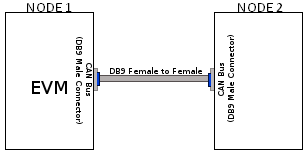
|
|
|
| DB9 to DB9 | Header to Header | Header to DB9 |
Table: Various DCAN EVM Connection Configuration
Equipment
Female DB9 Cable
A male DB9 connector is used on select evms. Therefore, a female DB9/Serial Port/RS 232 cable must be used to connect with the evm. Wheather the other end of the cable is female or male will depend on if the other CAN device the user will be connecting to.
Jumper Wires
For evms whose DCAN pins are broken out via a header then a female jumper wire would be best to use to connect to the various DCAN pins on the evm. Note some evms have CAN H (typically header pin 1), GND (typically middle header) and CAN L (typically the third header). Its important to always connect the CAN’s GND pin to what other device your connecting to. Only exception are the evms that don’t include the CAN GND pin.
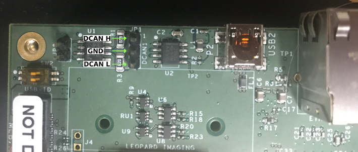
|
| Example of DCAN header on DRA72 EVM |
NOTE Its important for the user to verify which header pin is associated with the various CAN signals. Unless there are already silk screens the user may need to double check the evm’s schematic.
Custom DB9 to Header Cable
Typically CAN devices use a DB9 connection therefore for evms whose CAN pins are broken out via a header it is helpful to create a header to DB9 connector cable. This custom cable is simple to make. Either a male or female DB9 connector (not cable) must be purchased along with three female jumper wires.
Snip one end of each of the jumper wires and expose some of the wiring. Now solder each of the exposed wires to pin 7 (CAN H), pin 2 (CAN L) and pin 3 (GND). Make sure your soldering on the side of the DB9 that has the metal lip meant to push some of the exposed wire into and soldering to the correct pins correctly. Use the below diagram as a reference.
|
|
|
| Wiring Diagram | Example of completed cable. |
CAN Utilities
There may be other userspace applications that can be used to interact with the CAN bus but the SDK supports using Canutils which is already included in the sdk filesystem.
NOTE These instructions are for can0 (first and perhaps only CAN instance enabled). If the board has multiple CAN instances enabled then they can be referenced by incrementing the CAN instance number. For example 2 CAN instances will have can0 and can1.
Quick Steps
Initialize CAN Bus
- Set bit-timing
Set the bit-rate to 50Kbits/sec with triple sampling using the following command
$ canconfig can0 bitrate 50000 ctrlmode triple-sampling on
- Set bit-timing (loopback mode)
Set the bit-rate to 50Kbits/sec with triple sampling in the loopback mode using the following command
$ canconfig can0 bitrate 50000 ctrlmode triple-sampling on loopback on
Start CAN Bus
- Device bring up
Bring up the device using the command:
$ canconfig can0 start
NOTE The default state when starting a previously powered off CAN device is called “Error-Active”. So don’t worry when you see this command when you first start the CAN instance.
Send or Receive Packets
- Transfer packets
Packet transmission can be achieve by using cansend and cansequence utilities.
- Transmit 8 bytes with standard packet id number as 0x10
$ cansend can0 -i 0x10 0x11 0x22 0x33 0x44 0x55 0x66 0x77 0x88
e. Transmit a sequence of numbers from 0x00-0xFF and roll-back in a continuous loop
$ cansequence can0 -p
- Receive packets
Stop CAN Bus
Packet reception can be achieve by using candump utility
$ candump can0
Advanced Usage
Statistics of CAN
Statistics of CAN device can be seen from these commands
$ ip -d -s link show can0
Below command also used to know the details
$ cat /proc/net/can/stats
Error frame details
DCAN IP Error details
If the CAN bus is not properly connected or some hardware issues DCAN has the intelligence to generate an Error interrupt and corresponding error details on hardware registers.
In CAN terminology errors are divided into three categories
- Error warning state, this state is reached if the error count of transmit or receive is more than 96.
- Error passive state, this state is reached if the core still detecting more errors and error counter reaches 127 then bus will enter into
- Bus off state, still seeing the problems then it will go to Bus off mode.
DCAN driver provides
For the above error state, driver will send the error frames to inform that there is error encountered. Frame details with respect to different states are listed here:
- Error warning frame
<0x004> [8] 00 08 00 00 00 00 60 00
ID for error warning is 0x004 [8] represents 8 bytes have received 0x08 at 2nd byte represents type of error warning. 0x08 for transmission error warning, 0x04 for receive error warning frame 0x60 at 7th byte represent tx error count.
- Error passive frame
<0x004> [8] 00 10 00 00 00 00 00 64
ID for error passive frame is 0x004 [8] represents 8 bytes have received 0x10 at 2nd byte represents type of error passive. 0x10 for receive error passive, 0x20 for transmission error passive 0x64 at 8th byte represent rx error count.
- Buss off state
<0x040> [8] 00 00 00 00 00 00 00 00
ID for bus-off state is 0x040
Error frames display with candump
candump has the capability to display the error frames along with data frames on the console. Some of the error frames details are mentioned in the previous section
$ candump can0 --error
Linux Driver Configuration
- DCAN device driver in Linux is provided as a networking driver that confirms to the socketCAN interface
- The driver is currently build-into the kernel with the right configuration items enabled (details below)
Detailed Kernel Configuration
The SoC specific kernel configuration included in the SDK by default enables full support for the DCAN driver. Therefore, manually enabling these options are not required if your using the provided kernel config (defconfig).
The below CAN specific drivers are the bare minimum needed to enable DCAN driver:
- CAN bus subsystem support
- Bosch C_CAN/D_CAN devices
- CAN_C_CAN_PLATFORM
Four additional drivers are required to utilize all the CAN features:
- Raw CAN Protocol (raw access with CAN-ID filtering)
- Broadcast Manager CAN Protocol (with content filtering)
- CAN Gateway/Router (with netlink configuration)
- CAN bit-timing calculation
[*] Networking support ->
   <*|M> CAN bus subsystem support ->
      <*|M> Raw CAN Protocol (raw access with CAN-ID filtering)
      <*|M> Broadcast Manager CAN Protocol (with content filtering)
      <*|M> CAN Gateway/Router (with netlink configuration)
         CAN Device Drivers ->
            <*|M>   Platform CAN drivers with Netlink support
            [*]     CAN bit-timing calculation
            <*|M>   Bosch C_CAN/D_CAN devices ->
               <M> Generic Platform Bus based C_CAN/D_CAN driver
NOTE *|M means can be either be built into the kernel or enabled as a kernel module.
DCAN driver Architecture
DCAN driver architecture shown in the figure below, is mainly divided into three layers Viz user space, kernel space and hardware.
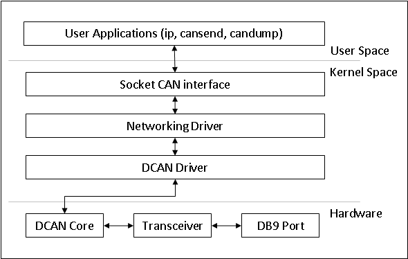
User Space
CAN utils are used as the application binaries for transfer/receive frames. These utils are very useful for debugging the driver.
Kernel Space
This layer mainly consists of the socketcan interface, network layer and DCAN driver.
Socketcan interface provides a socket interface to user space applications and which builds upon the Linux network layer. DCAN device driver for CAN controller hardware registers itself with the Linux network layer as a network device. So that CAN frames from the controller can be passed up to the network layer and on to the CAN protocol family module and vice-versa.
The protocol family module provides an API for transport protocol modules to register, so that any number of transport protocols can be loaded or unloaded dynamically.
In fact, the can core module alone does not provide any protocol and cannot be used without loading at least one additional protocol module. Multiple sockets can be opened at the same time, on different or the same protocol module and they can listen/send frames on different or the same CAN IDs.
Several sockets listening on the same interface for frames with the same CAN ID are all passed the same received matching CAN frames. An application wishing to communicate using a specific transport protocol, e.g. ISO-TP, just selects that protocol when opening the socket. Then can read and write application data byte streams, without having to deal with CAN-IDs, frames, etc.
Hardware
This layer mainly consisting of DCAN core and DCAN IO pins for packet Transmission or reception.
Driver Location
| S.No | Location | Description |
|---|---|---|
| 1 | drivers/net/can/c_can/c_can.c | DCAN driver core file |
| 2 | drivers/net/can/c_can/c_can_platform.c | Platform/SoC DCAN bus driver |
3.3.4.8. DSS
Introduction
This page gives a basic description of DSS hardware, the Linux kernel drivers (omapdss and omapdrm) and various TI boards that use DSS. The technical reference manual (TRM) for the SoC in question, and the board documentation give more detailed descriptions.
This page applies to TI’s v4.9 kernel, but most of it is also valid for mainline and for older kernels. Some features may be missing from mainline.
Supported Devices
There are many DSS IP versions, all of which support slightly different set of features. All the DSS IP versions are supported by the same driver.
This page applies to the following TI SoCs or SoC families: OMAP2, OMAP3, OMAP4, OMAP5, AM5, AM4, DRA7, K2G.
Hardware Architecture
The Display Subsystem (DSS) is a hardware block responsible for fetching pixel data from memory and sending it to a display peripheral like an LCD panel or a HDMI monitor. DSS hardware can be divided into two major parts: 1) DISPC, which handles fetching the pixel data, doing color conversions, composition, and other pixel manipulation, and 2) encoders, which encode the raw pixel data to standard display signals, like HDMI or MIPI DPI. In addition to the SoC’s DSS, boards often contain external encoders (for example, DPI to DVI encoder) and display panels.
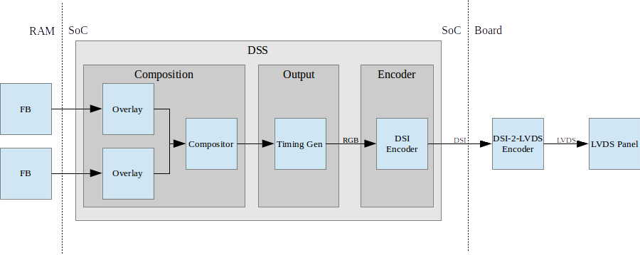
Simplified example setup where two overlays are merged into one output, which is encoded into DSI, then to LVDS, and shown on an LVDS panel.
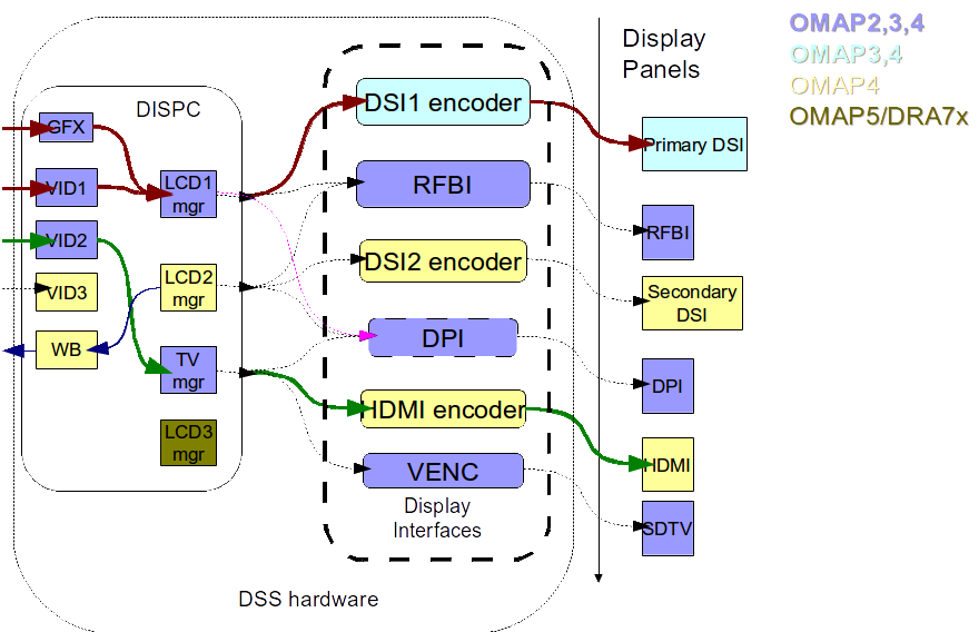
An overview of the DSS hardware. The arrows show how ovlerlays/pipelines are connected to overlay managers, which are further connected to encoders, which finally create an encoded pixel stream for display on to LCD or TV. The different colors of the blocks show the new sub-blocks added in subsequent DSS revisions
Display Controller (DISPC)
DISPC is the block which is responsible of fetching pixel data from the memory through DMA pipelines, and then create a pixel stream for the encoder. The pixel stream comprises of a composition of one or more image layers which we finally want to present on the display. DISPC can be split into 2 major sub-blocks:
Overlays
Overlays (or Pipelines or DMA channels) consist of the HW block which perform DMA to fetch image pixels (of different color formats) from RAM. Besides performing DMA, overlays perform other functions like replication, ARGB expansion, scaling, color conversion, VC1 range mapping on the input pixels before it’s passed on to the overlay manager. An overlay manager receives pixel data from one or more such pipelines, and performs the task of composing them and passing it on to the encoder.
Most DSS IP versions has two types of overlays: a GFX overlay and a number of VIDEO overlays. GFX overlay doesn’t support scaling or YUV color formats and are generally intended to display a user interface. VIDEO overlays support up/down scaling and YUV color formats. The number of overlays within DSS varies with the DSS IP version used in the SoC.
Overlay Managers (Compositors and timing generators)
Overlay managers are the blocks which take pixel data from one or more overlays, layer them to form a composition, and create a pixel stream with the timings as per required by the encoder/panel.
The compositor part takes pixel data from multiple overlays, composing them on the basis of their position with respect to the complete overlay manager size. Tasks like alpha blending, color-keying, z-order and color phase rotation, dithering are also performed by the compositor in the overlay manager.
The timing generator part of the overlay manager is responsible of providing the pixel stream generated by the compositor above according to the timings desired by the encoder or the panel. The timing generator is a state machine which provides RGB data along with control signals like pixel clock, hsync, vsync, data enable. This timing info is used by the encoder/panel to display the composited frame on the screen.
Most DSS IP versions have two types of overlay managers. LCD managers are primarily used for encoders like DPI, DSI and RFBI which connect to LCD panels. The timing generator derives its pixel clock from either the DSS functional clock, or a PLL within the DSS. TV managers are primarily used for encoders like HDMI and VENC which connect to TV and monitors. The timing generator derives gets the pixel clock from the connected encoder.
The number of overlay managers within DSS varies with the DSS IP version used in the SoC.
Display Encoders (or interfaces)
Encoders take a pixel stream from an overlay manager, and encode it into a standard video signal which is understood by the LCD panel/monitor. These video standards are specified by MIPI or general video/display bodies.
- MIPI DPI encoder: This is the simplest encoder, it passes the overlay manager video port output (consisting of RGB data lines and control signals) directly to SoC pins. The number of RGB data lines used is configurable, and is set on the basis of the color depth supported by the LCD panel.
- HDMI encoder: This adapts the HDMI spec. It consists of a CORE block which implements the HDMI protocol, a PLL block which provides the clock required for the pixel clock and HDMI TMDS lines, and a PHY block which encodes the pixels and data into the TMDS format.
- MIPI DSI encoder: This encoder takes parallel RGB data from an overlay manager video port, and encodes it into a serial format. It consists of the Protocol engine which implements the MIPI DSI spec to create serial data, and command information, a PLL block which provides clocks to the overlay manager, protocol engine and the PHY, a DSI PHY block which follows the MIPI D-PHY spec, this uses a LVDS like protocol to transmit serial data to the DSI display. DSI supports 2 modes, command and video modes. More info can be found in the TRM.
- MIPI DBI/RFBI encoder: This encoder transmits data to a panel without any timing generation info. The panel is expected to have an internal buffer which it displays on to the LCD using it’s own timing generator.
- VENC encoder: This encoder converts digital pixel data into a composite or s-video analog output supporting the NTSC and PAL standards. It’s hardly used these days.
The number and types of encoders within DSS varies with the DSS IP version used in the SoC.
SoC Hardware Features
AM4
- 1 GFX overlay
- XRGB4444, ARGB4444, RGB565
- RGB888
- XRGB8888, ARGB8888, RGBA8888
- 2 VIDEO overlays
- XRGB4444, ARGB4444 (VID2), RGB565
- RGB888
- XRGB8888, ARGB8888 (VID2), RGBA8888 (VID2)
- UYVY, YUYV
- 1 MIPI DPI output
OMAP5
- 1 GFX overlay
- XRGB4444, RGBX4444, ARGB4444, RGBA4444, RGB565, XRGB1555, ARGB1555
- RGB888
- XRGB8888, RGBX8888, ARGB8888, RGBA8888, BGRA8888
- 3 VIDEO overlays
- XRGB4444, RGBX4444, ARGB4444, RGBA4444, RGB565, XRGB1555, ARGB1555
- RGB888
- XRGB8888, RGBX8888, ARGB8888, RGBA8888, BGRA8888
- UYVY, YUYV, NV12
- 1 MIPI DPI outputs
- 2 MIPI DSI outputs
- 1 HDMI output
DRA7 / AM5
- 1 GFX overlay
- XRGB4444, RGBX4444, ARGB4444, RGBA4444, RGB565, XRGB1555, ARGB1555
- RGB888
- XRGB8888, RGBX8888, ARGB8888, RGBA8888, BGRA8888
- 3 VIDEO overlays
- XRGB4444, RGBX4444, ARGB4444, RGBA4444, RGB565, XRGB1555, ARGB1555
- RGB888
- XRGB8888, RGBX8888, ARGB8888, RGBA8888, BGRA8888
- UYVY, YUYV, NV12
- 3 MIPI DPI outputs
- 1 HDMI output
Driver Architecture
The driver for DSS IP is omapdrm. omapdrm is a Direct Rendering Manager (DRM) driver, located in the directory drivers/gpu/drm/omapdrm/ in the kernel tree. omapdrm does not implement any 3D GPU features, only the Kernel Mode Setting (KMS) features, used to display pixel data on a display.
In addition to omapdrm, there are a number of encoder and panel drivers implementing support for encoders and panels located in drivers/gpu/drm/omapdrm/displays/ .
omapdrm
omapdrm is internally divided into smaller drivers for each DSS IP submodule. These include DPI, DSI, HDMI drivers.
The mapping of DRM entities to DSS hardware is roughly as follows:
plane     -> DSS pipeline/overlay
crtc      -> DSS overlay manager
encoder   -> DSS output, encoder, display
connector -> DSS output, encoder, display
Driver Features
Note: this is not a comprehensive list of features supported/not supported.
Supported Features
LCD Outputs:
- MIPI DPI
- Active matrix
- RGB
HDMI output:
- Progressive
- Interlace (with progressive content)
- 24-bit RGB
DRM Plane Features:
- Scaler
- Z-order
- Global alpha blending
- Alpha blending (pre-multipled & non-pre-multiplied)
DRM CRTC Features:
- Background color
- Transparency color keying
- Color Phase Rotation
Unsupported Features/Limitations
- Rotation/Tiler 2D (Partially supported by the driver, but almost unusable due to HW limitations)
- Interlaced content is not supported.
- Information about interlace top/bottom fields is not given to the userspace, and the userspace has no control if a buffer is shown on top/bottom.
- On DRA7 and AM5 the driver has limitations on the possible combinations of VOUTs that are usable at the same time. The maximum number of supported VOUTs is the same as the number of video PLLs, i.e. 1 on DRA72x/AM571x and 2 on DRA74x/AM572x. When using two VOUTs, VOUT1 and VOUT3 should be used (other combinations can be used with minor driver modification).
LCD output:
- CLUT (Color Look-Up Table) color formats are not supported (BITMAP1, BITMAP2, BITMAP4, BITMAP8)
- Passive matrix
- TDM
- BT-656/1120
- MIPI DBI/RFBI
- Interlace
HDMI output:
- HDCP
- Deep color modes
- YUV output
Driver Configuration
Kernel Configuration Options
omapdrm supports building both as built-in or as a module.
omapdrm can be found under “Device Drivers/Graphics support” in the kernel menuconfig. You need to enable DRM (CONFIG_DRM) before you can enable omapdrm (CONFIG_DRM_OMAP).
- Enable OMAP2+ Display Subsystem support (CONFIG_OMAP2_DSS) for
AM4/OMAP5/DRA7/AM5 SoCs
- From the submenu, select the DSS outputs you need
- Enable TI DSS6 support (CONFIG_TI_DSS6) for K2G SoC
- Enable the encoders and panels under OMAPDRM External Display Device Drivers
Driver Usage
Loading omapdrm
If built as a module, you need to load all the drm, omapdrm, encoder and panel modules before omapdrm will start. When omapdrm starts, it will prints something along these lines:
[   12.858392] [drm] Supports vblank timestamp caching Rev 2 (21.10.2013).
[   12.865153] [drm] No driver support for vblank timestamp query.
[   12.884131] [drm] Enabling DMM ywrap scrolling
[   12.891551] omapdrm omapdrm.0: fb0: omapdrm frame buffer device
[   12.926796] [drm] Initialized omapdrm 1.0.0 20110917 on minor 0
Using omapdrm
omapdrm is usually used by the windowing system like X server or Weston, so normally users don’t need to use omapdrm directly.
omapdrm device appears under /dev/dri/ directory, normally card0.
There are also newer DRM device nodes, controlD64 and renderD128 which point to the same omapdrm device. controlD64 is a “control” node, used for mode setting. renderD128 is a “render” node, which in omapdrm’s case means that only buffer allocations can be done via the render node. The render node can be given more relaxed access restrictions, as the applications can only do buffer allocations from there, and cannot affect the system (except by allocating all the memory).
Low level userspace applications can use omapdrm via DRM ioctls. This is made a bit easier with libdrm, which is a wrapper library around DRM ioctls.
libdrm is included in TI releases and its sources can be found from:
git://anongit.freedesktop.org/git/mesa/drm
libdrm also contains ‘modetest’ tool, which can be used to get basic information about DRM state, and to show a test pattern on a display.
Another option is kms++, a C++11 library for kernel mode setting which includes a bunch of test utilities and also V4L2 classes and Python wrappers for DRM and V4L2. kms++ can be found from:
https://github.com/tomba/kmsxx
There are also other examples and tests that can be used to learn about DRM:
Dual camera demo:
http://git.ti.com/sitara-linux/dual-camera-demo/trees/master
omapdrm properties
omapdrm supports configuration via DRM properties. Many of them are standard, but some are omapdrm specific.
| Property | Object | Description |
|---|---|---|
| zorder | plane | Z order of a plane. The higher the number the more top the plane is, hiding other planes beneath it. This is supported on OMAP4+ DSS IPs. Earlier DSS IPs have a fixed z-order. |
| global_alpha | plane | Global alpha value for a plane. |
| pre_mult_alpha | plane | If set, the pixel data is considered pre-multiplied with alpha. |
| COLOR_ENCODING | plane | OMAP4+: Selects between BT.601 and BT.709 YCbCr encoding. |
| COLOR_RANGE | plane | OMAP4+: Selects between full range and limited range YCbCr encoding. |
| trans-key-mode | crtc | Transparency key mode: disable, gfx-dts, vid-src. |
| trans-key | crtc | Transparency key color. |
| background | crtc | Background (“default”) color. |
| alpha_blender | crtc | OMAP3/AM4: Enable alpha blender, which also changes the fixed z-order. |
| CTM | crtc | OMAP4+: Color Transformation Matrix blob property. Implemented trough Color phase rotation matrix in DSS IP. Applied after gamma table. Not available on OMAP4+ TV output. |
| GAMMA_LUT | crtc | OMAP4+ & DSS6: Blob property to set the gamma lookup table (LUT) mapping pixel data sent to the connector. |
| GAMMA_LUT_SIZE | crtc | OMAP4+ & DSS6: Number of elements in gammma lookup table. |
Buffers
The buffers used for omapdrm can be either allocated from omapdrm or imported from some other driver (dmabuf import).
omapdrm supports generic DRM dumb buffers and omapdrm specific buffers (omap_bo). Dumb buffers are allocated using the generic DRM_IOCTL_MODE_CREATE_DUMB ioctl. omap_bos are allocated using the omapdrm specific DRM_IOCTL_OMAP_GEM_NEW ioctl, but libdrm offers wrappers for omap_bo allocation.
On SoCs with TILER (OMAP4/5, AM5, DRA7) the driver supports scatter-gather lists for both allocated and imported buffers. On SoCs without TILER the allocated memory is always from the contiguous DMA memory pool, and imported memory must be contiguous memory.
Debugging
There are two debugfs directiories that can be used when debugging omapdrm:
/sys/kernel/debug/omapdrm/ contains debugfs files for the DSS hardware. It can be used to get register dumps of the IP blocks, and to get information about the clock setup.
/sys/kernel/debug/dri/ contains debugfs files for the DRM. It can be used to see the framebuffers allocated, the connectors, information about tiler.
fbdev emulation (/dev/fb0)
DRM framework supports “emulating” the legacy fbdev API. This feature can be enabled or disabled in the kernel config (CONFIG_DRM_FBDEV_EMULATION). The fbdev emulation offers only basic feature set and the fb is shown on the first display. Fbdev emulation is mainly intended for kernel console or boot splash screens.
Module parameters
displays
‘displays’ module parameter can be used to reorder or remove the displays that omapdrm uses. If the board has two displays, LCD and HDMI, and the device tree data defines LCD as display0 and HDMI as display1, then:
omapdrm.displays=0,1 - represents the original order (LCD, HDMI)
omapdrm.displays=1,0 - represents reverse order (HDMI, LCD)
omapdrm.displays=0 - only the LCD is enabled
omapdrm.displays=1 - only the HDMI is enabled
omapdrm.displays=-1 - disable all displays
TI Board Specific Information
The below section provides details on TI board specific DSS features and limitation.
AM4 Boards
Features & Limitations
On the EVM board, we use DPI LCD panel of resolution 800 x 480. The LCD panel is 7 inch touch panel (OSD057T0559-34TS) from OSD displays. Silicon Image’s SiI9022 is the DPI to HDMI converter available on board to provide HDMI output. Due to memory bandwidth limitations the board only supports a maximum of 720p@60.
As AM4 only has a single output, both LCD and HDMI cannot be enabled at the same time. Selecting the display to be used if done by using the appropriate .dtb file.
DRA7 EVM
On the DRA7 EVM, DSS outputs are connected as follows:
DPI1/VOUT1 -> LCD panel (LCD type can be 7" or 10" LG or 10" OSD panel connected via a daughter card).
DPI2/VOUT2 -> Unused.
DPI3/VOUT3 -> FPD Link (Optional. Panel to be connected to a serializer/de-serializer board via FPDLink cable).
HDMI -> HDMI connector.
The used LCD panel is chosen by selecting the appropriate .dtb file.
3.3.4.9. LCDC
AM335x LCDC DRM Display Driver
Introduction
This page gives a brief description of LCDC usage with tilcdc DRM driver. The obsolete fbdev driver wiki page also remains at the end of this page.
This document applies TI’s v4.4 kernel and mainline v4.9 kernel with tilcdc DRM atomic modeset support.
Generic DRM Information
What is DRM: https://dri.freedesktop.org/wiki/DRM/
What do the abbreviations KMS/GEM/DRM actually stand for: Kernel Mode Setting, Graphics Execution Manager, Direct Rendering Manager.
Where can I find DRM documentation?
- Online at: https://www.kernel.org/doc/htmldocs/drm/index.html
- Or in kernel directory:
- make htmldocs
Use web browser to view: Documentation/DocBook/drm.html
- DRM (dri/kms/gem) documentation is available here
Hardware and How It Is Used
The LCD controller can be used in two independent modes. Either in the raster controller mode or in LCD interface display driver (LIDD) mode. The tilcdc driver support only raster controller mode.
Compared to most other DRM supported devices the LCDC provides very limited functionality. It supports only one simple framebuffer or alternatively two framebuffers that are automatically flipped back and forth. The tilcdc driver uses single buffer mode and flips framebuffer by changing the framebuffer’s DMA address. This does not interfere with the DMA of the currently drawn frame.
The LCDC supports 1-, 2-, 4-, 8-, 12-, 16-, and 24-bits per pixel modes. The 1-, 2-, 4-, and 8-bpp modes are palette modes and are not supported by the tilcdc driver. With the 12-, 16-, and 24-bit modes the choice is limited to 16 and 24 bpp modes, and the 24 bpp mode is only supported by revision 2 LCDC. There is also a problem is using 16- and 24-bit modes with same HW, see tilcdc Supported Features below.
LCDC memory bandwidth issues
LCDC sometimes suffers from memory bandwidth issues when high pixel clocks and high bits per pixel colour formats are used. These bandwidth issues manifest themselves as DMA FIFO underflow and frame synchronization lost errors. The problem is solved on Beaglebone-Black and am335x-evm with this patch. The patch is available in u-boot release version ti2017.01 (Processor SDK version 4.0) onwards. A similar u-boot change is needed for any other HW suffering from the same problem. Please check the ddr_data for am3-evm or beaglebone-black in the u-boot config. If after using the patch you still see issues, you may need to further tune the value of REG_PR_OLD_COUNT per your system need.
tilcdc Supported Features
- RGB565 color format
- or RGB888/XRGB8888 color formats (LCDC rev2 only)
- The 16-bit and 24-bit video has Red and Blue wires swapped and depending on the wiring of the board ether 16-bit or 24-video is in BGR format (see section 3.1.1 in AM335x Silicon Errata)
- Panel timings controlled from dts file
- TDA998x HDMI encoder support on BeagleBone Black
- Pixel clock to 126MHz allowing resolutions up to 1920x1080p24
- Fbdev emulation is provided through /dev/fb0
- HDMI audio support with corresponding ALSA sink (not in mainline for the time being)
- HDMI EDID support
- DRM Atomic modeset support since Linux 4.9 and in ti2016.04
tilcdc Unsupported Features:
- No HDMI hotplug
- 1920x1080@60 is not supported due to pixel clock requirements being too high for the AM335x hardware.
Configuring into kernel build:
- By default DRM support for LCDC is not built in to the kernel when using omap2plus_defconfig.
- Make sure that the following are disabled from .config as the
fbdev driver cannot coexist with the DRM driver.
- CONFIG_FB_DA8XX
- CONFIG_FB_DA8XX_TDA998X
- And add:
- CONFIG_DRM=y/m
- CONFIG_DRM_I2C_NXP_TDA998X=y/m
- CONFIG_DRM_TILCDC=y/m
If using modules, it is enough to load tilcdc module, and tda998x module if using beaglebone-black. It does not matter in which order the modules are loaded.
Required Device Tree Nodes:
- See .txt files in - Documentation/devicetree/bindings/drm/tilcdc
- For Beaglebone-Black see also: Documentation/devicetree/bindings/display/bridge/tda998x.txt
- The am335x-boneblack.dts, am335x-evm.dts, and am335x-evmsk.dts have the necessary nodes for LCDC DRM driver
Example Device Tree nodes to enable HDMI with DRM on BeagleBone Black:
&lcdc {
    status = "okay";

    port {
        lcdc_0: endpoint@0 {
            remote-endpoint = <&hdmi_0>;
        };
    };
};
&i2c0 {
    tda19988: tda19988 {
        compatible = "nxp,tda998x";
        reg = <0x70>;

        #sound-dai-cells = <0>;
        audio-ports = <  TDA998x_I2S 0x03>;

        ports {
            port@0 {
                hdmi_0: endpoint@0 {
                    remote-endpoint = <&lcdc_0>;
                };
            };
        };
    };
};
Examples for using DRM:
The drm userspace components and test applications are available from: https://cgit.freedesktop.org/mesa/drm/
A useful tool contained in this suite is modetest.
- On BeagleBone Black you can use modetest to try the different resolutions that are supported by the attached monitor.
- For example:
- modetest –s 5:1280x720@XB24
- Will change the HDMI output to 1280x720 – the XB24 tells modetest to use the correct pixel format of XBGR8888.
Legacy AM335x LCDC fbdev Display Driver
This driver is currently obsolete (has been since ti-linux-3.14.y), and is not actively maintained any more. Please use LCDC DRM driver instead.
Introduction:
- Where can I find fbdev documentation:
See Documentation/fb/framebuffer.txt Or online at: https://www.kernel.org/doc/Documentation/fb/framebuffer.txt
LCDC fbdev Supported Features:
- RGB32 pixel format (XBGR32 format)
- Panel timings controlled from dts file
- TDA998x HDMI encoder support on BeagleBone Black
- Pixel clock to 126MHz allowing resolutions up to 1920x1080p24
- Access to driver and framebuffer is through /dev/fb0
LCDC fbdev Unsupported Features:
- No HDMI audio support in fbdev driver
- No HDMI EDID support
- No HDMI hotplug
Configuring into kernel build:
- The necessary .config options are:
- CONFIG_FB_DA8XX
- CONFIG_FB_DA8XX_TDA998X
Required Device Tree Nodes (no HDMI)
- See Documentation/devicetree/bindings/video/da8xx_fb.txt
Required Device Tree Nodes (with HDMI)
- See arch/arm/boot/dts/am335x-boneblack.dts for complete example of how to use.
&i2c0 {
   hdmi1: hdmi@70 {
        compatible = "nxp,tda998x";
        reg = <0x70>;
  };
};

&lcdc {
   hdmi = <&hdmi1>;
   display-timings {
        /* provide your display timings here for HDMI */
   };
};
3.3.4.10. PWM
Introduction
PWMSS software architecture
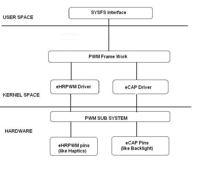
Driver Configuration
Procedure to build eHRPWM driver
Device Drivers --->
        <*> Pulse Width Modulation(PWM) Support --->
           <*> eHRPWM PWM support
Procedure to build eCAP driver
Device Drivers --->
        <*> Pulse Width Modulation(PWM) Support --->
           <*> eCAP PWM support
Driver Usage
eCAP
The current release of the driver supports only PWM mode. eCAP can be controlled from the user space through SYSFS interface. SYSFS interface for eCAP is available at
target$ cat /sys/class/pwm/pwmchipN
Where,
‘N’ is the eCAP instance.
- Request and Control attributes
- Configuration attributes
Note
- Below examples uses eCAP instance 0 (i = 0).
Type 1 attributes
- *export* Attribute.
Ask the kernel to export a PWM channel. Writing 0 to the export attribute Acquires the channel and writing 0 to the unexport attribute Frees/Releases the channel. Before performing any operations, device has to be requested first.
- Request the Device:
target$ echo 0 > /sys/class/pwm/pwmchip0/export
- free the device:
target$ echo 0 > /sys/class/pwm/pwmchip0/unexport
- *run* Attribute
Enable/disable the PWM channel
- Enable the PWM
target$ echo 1 > /sys/class/pwm/pwmchip0/pwm0/enable
- Disable the PWM
target$ echo 0 > /sys/class/pwm/pwmchip0/pwm0/enable
Type 2 attributes
- *period* Attribute
Enter the period in nano seconds value.
target$ echo 1000000000 > /sys /class/pwm/pwmchip0/pwm0/period
- *duty_cycle* Attribute
Enter the Duty cycle value in nanoseconds.
target$ echo val > /sys/class/pwm/pwmchip0/pwm0/duty_cycle
- *Polarity* Attribute.
Setup Signal Polarity
target$ echo 1 > /sys /class/pwm/pwmchip0/pwm0/polarity
target$ echo 0 > /sys /class/pwm/pwmchip0/pwm0/polarity
Controlling backlight
target$ echo val > /sys/class/pwm/pwmchip0/pwm0/duty_cycle
target$ echo val > /sys/class/backlight/backlight.8/brightness
‘val’ can range from 0 to 8.
3.3.4.11. GPIO
GPIO Driver Overview
The GPIO Driver enables the GPIO controllers available on the device. The driver configures the GPIO hardware and interfaces and makes them available to the sysfs interface for user space interaction or other device drivers that need to access pins. For example, a MMC/SD driver may need to read a GPIO as in input to determine if a card is present. The H/W GPIO controllers available will vary by SoC and system configuration.
Overview
The GPIO controllers allow interaction with GPIO pins for input/output and interrupt generation.
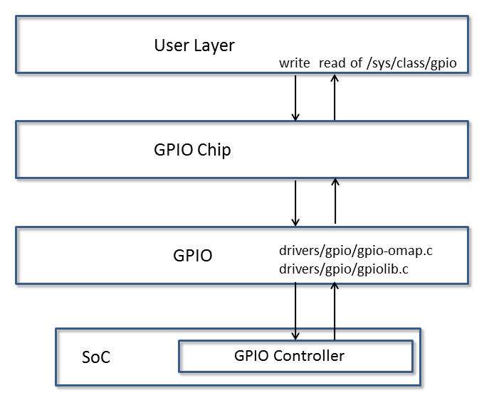
User Layer
The GPIO driver can be used via the sysfs interface in user space or by other drivers that may need to access pins as either input/outputs or interrupts. More information about this driver and GPIO usage in Linux can be found in the kernel documentation:
sysfs
The sysfs interface is for GPIO is located in the kernel at /sys/class/gpio. More information about this interface can also be found in the kernel sources:
For controlling LEDs and Buttons, the kernel has standard drivers, “leds-gpio” and “gpio_keys”, respectively, that should be used instead of GPIO directly.
Consuming Drivers
The GPIO Driver can also be easily leveraged by other drivers to “consume” a GPIO.
For an example of a driver using a GPIO pin, examine this entry in a dts file for how the MMC/SD interface could use a GPIO as a card detect pin here.
Features
- Access GPIO from user space as input or output
- Leverage GPIO from another “consumer” driver
Power Management
`` @am33xx_pinmux { ``
pinctrl-names = "default";
pinctrl-0 = <&test_keys>;
...
test_keys: test_keys {
  0x74 (PIN_INPUT_PULLDOWN | MUX_MODE7);  /* gpmc_wpn.gpio0_31 */
};
...
keys: test_keys@0 {
  compatible = "gpio-keys";
  #address-cells = <1>;
  #size-cells = <0>;
  autorepeat;
  test@0 {
    label = "J4-pin21";
    linux,code = <155>;
    gpios = <&gpio0 31 GPIO_ACTIVE_LOW>;
    gpio-key,wakeup;
  };
};
...
};
3.3.4.12. I2C
Introduction
The device contains high-speed (HS) inter-integrated circuit (I2C) controllers (I2Ci modules, where i = 1, 2, 3 ...), each of which provides an interface between a local host (LH), such as a digital signal processor (DSP), and any I2C-bus-compatible device that connects through the I2C serial bus. External components attached to the I2C bus can serially transmit and receive up to 8 bits of data to and from the LH device through the 2-wire I2C interface.
Each HS I2C controller can be configured to act like a slave or master I2C-compatible device. I2C controllers can work at different frequencies such as 100 KHz, 400 KHz and 3.4 MHz.
For more info, refer to the I2C controller chapter in the respective SOC TRM.
Setting up
Omap I2C is enabled by default in omap2plus_defconfig.
Testing
Test1:
  Check for the following in the boot log
  omap_i2c reg.i2c: bus0 rev0.12 at X KHz
Test2:
  Use the following utilities to check the i2c functionality.
  i2cdump -f -y bus slaveaddr b
     This will dump the register content of the slave at respective bus.
  i2cset -f -y bus slaveaddr register value b
     This will write a 'value' to the 'register' of the device with address 'slaveaddr'.
  i2cget -f -y bus slaveaddr register b
     This will read from the 'register' of the device with address 'slaveaddr'.
  Above testing helps if the slave address clocks are enabled and you can use the
  above tools to quickly get/set the value to just sanity check the i2c functionality.
Test3:
    Check for the devices connected to the I2C.
    Run tests applicable for those devices to see if I2c read/write works fine.
3.3.4.13. CPSW
3.3.4.13.1. Introduction
TI Common Platform Ethernet Switch (CPSW) is a three port switch (one CPU port and two external ports). The CPSW or Ethernet Switch driver follows the standard Linux network interface architecture.
The driver supports the following features:
- 10/100/1000 Mbps mode of operation.
- Auto negotiation.
- Linux NAPI support
- Switch Support
- VLAN (Subscription common for all ports)
- Ethertool (Supports only Slave 0 decided in cpsw DT node)
- Dual Standalone EMAC mode
Driver Configuration
To enable/disable Networking support, start the Linux Kernel Configuration tool:
$ make menuconfig
Select Device Drivers from the main menu.
...
...
Power management options --->
[*] Networking support --->
Device Drivers --->
File systems --->
Kernel hacking --->
...
...
Select Network device support as shown below:
...
...
[*] Multiple devices driver support (RAID and LVM)  --->
< > Generic Target Core Mod (TCM) and ConfigFS Infrastructure  ----
[*]Network device support --->
Input device support  --->
Character devices  --->
...
...
Select Ethernet driver support as shown below:
...
...
*** CAIF transport drivers ***
Distributed Switch Architecture drivers  --->
[*]   Ethernet driver support  --->
-*-   PHY Device support and infrastructure  --->
< >   Micrel KS8995MA 5-ports 10/100 managed Ethernet switch
< >   PPP (point-to-point protocol) support
...
...
Select ** as shown here:
...
[*]   Texas Instruments (TI) devices
< >     TI DaVinci EMAC Support
-*-     TI DaVinci MDIO Support
-*-     TI DaVinci CPDMA Support
-*-     TI CPSW Switch Phy sel Support
<*>     TI CPSW Switch Support
[ ]       TI Common Platform Time Sync (CPTS) Support
Module Build
Module build for the cpsw driver is supported. To do this, at all the places mentioned in the section above select module build (short-cut key M).
Select ** as shown here:
...
 [*]   Texas Instruments (TI) devices
 < >     TI DaVinci EMAC Support
 <M>     TI DaVinci MDIO Support
 <M>     TI DaVinci CPDMA Support
 -*-     TI CPSW Switch Phy sel Support
 <M>     TI CPSW Switch Support
 [ ]       TI Common Platform Time Sync (CPTS) Support
Interrupt Pacing
CPSW interrupt pacing feature limits the number of interrupts that occur during a given period of time. For heavily loaded systems in which interrupts can occur at a very high rate, the performance benefit is significant due to minimizing the overhead associated with servicing each interrupt.
To enable interrupt pacing, please execute below mentioned command using ethtool utility:
ethtool -C eth0 rx-usecs <delayperiod>
To achieve maximum performance set <delayperiod> to 500/250 depends on your platform
Configure number of TX/RX descriptors
By default CPSW allocates and uses as much CPPI Buffer Descriptors descriptors as can fit into the internal CPSW SRAM, which is usually is 256 descriptors. This is not enough for many high network throughput use-cases where packet loss rate should be minimized, so more RX/TX CPPI Buffer Descriptors need to be used.
CPSW allows to place and use CPPI Buffer Descriptors not only in SRAM, but also in DDR. The “descs_pool_size” module parameter can be used to setup total number of CPPI Buffer Descriptors to be allocated and used for both RX/TX path.
To configure descs_pool_size from kernel boot cmdline:
ti_cpsw.descs_pool_size=4096
To configure descs_pool_size from cmdline:
insmod ti_cpsw descs_pool_size=4096
Hence, the CPSW uses one pool of descriptors for both RX and TX which by default split between all channels proportionally depending on total number of CPDMA channels and number of TX and RX channels. Number of CPPI Buffer Descriptors allocated for RX and TX path can be customized via ethtool ‘-G’ command:
ethtool -G <devname> rx <number of descriptors>
ethtool ‘-G’ command will accept only number of RX entries and rest of descriptors will be arranged for TX automatically.
Defaults and limitations:
- minimum number of rx descriptors is max number of CPDMA channels (8)
  to be able to set at least one CPPI Buffer Descriptor per channel
- maximum number of rx descriptors is (descs_pool_size - max number of CPDMA channels (8))
- by default, descriptors will be split equally between RX/TX path
- any values passed in "tx" parameter will be ignored
Examples:
# ethtool -g eth0
       Pre-set maximums:
       RX:             7372
       RX Mini:        0
       RX Jumbo:       0
       TX:             0
       Current hardware settings:
       RX:             4096
       RX Mini:        0
       RX Jumbo:       0
       TX:             4096

# ethtool -G eth0 rx 7372
# ethtool -g eth0
       Ring parameters for eth0:
       Pre-set maximums:
       RX:             7372
       RX Mini:        0
       RX Jumbo:       0
       TX:             0
       Current hardware settings:
       RX:             7372
       RX Mini:        0
       RX Jumbo:       0
       TX:             820
VLAN Config
VLAN can be added/deleted using vconfig utility. In switch mode added vlan will be subscribed to all the ports, in Dual EMAC mode added VLAN will be subscribed to host port and the respective slave ports.
Examples
VLAN Add
vconfig add eth0 5
VLAN del
vconfig rem eth0 5
IP assigning
IP address can be assigned to the VLAN interface either via udhcpc when a VLAN aware dhcp server is present or via static ip asigning using ifconfig.
Once VLAN is added, it will create a new entry in Ethernet interfaces like eth0.5, below is an example how it check the vlan interface
root@dra7xx-evm:~# ifconfig eth0.5
eth0.5    Link encap:Ethernet  HWaddr 20:CD:39:2B:C7:BE
          inet addr:192.168.10.5  Bcast:192.168.10.255  Mask:255.255.255.0
          UP BROADCAST RUNNING MULTICAST  MTU:1500  Metric:1
          RX packets:0 errors:0 dropped:0 overruns:0 frame:0
          TX packets:0 errors:0 dropped:0 overruns:0 carrier:0
          collisions:0 txqueuelen:0
          RX bytes:0 (0.0 B)  TX bytes:0 (0.0 B)
Packet Send/Receive
To Send or receive packets with the VLAN tag, bind the socket to the proper ethernet interface shown above and can send/receive via that socket-fd.
Multicast Add/Delete
Multicast MAC address can be added/deleted using the following ioctl commands SIOCADDMULTI and SIOCDELMULTI
Example
The following is the example to add and delete muliticast address 01:80:c2:00:00:0e
Add Multicast address
struct ifreq ifr;
ifr.ifr_hwaddr.sa_data[0] = 0x01;
ifr.ifr_hwaddr.sa_data[1] = 0x80;
ifr.ifr_hwaddr.sa_data[2] = 0xC2;
ifr.ifr_hwaddr.sa_data[3] = 0x00;
ifr.ifr_hwaddr.sa_data[4] = 0x00;
ifr.ifr_hwaddr.sa_data[5] = 0x0E;
ioctl(sockfd, SIOCADDMULTI, &ifr);
Delete Multicast address
struct ifreq ifr;
ifr.ifr_hwaddr.sa_data[0] = 0x01;
ifr.ifr_hwaddr.sa_data[1] = 0x80;
ifr.ifr_hwaddr.sa_data[2] = 0xC2;
ifr.ifr_hwaddr.sa_data[3] = 0x00;
ifr.ifr_hwaddr.sa_data[4] = 0x00;
ifr.ifr_hwaddr.sa_data[5] = 0x0E;
ioctl(sockfd, SIOCDELMULTI, &ifr);
Note
This interface does not support VLANs.
Dual Standalone EMAC mode
Introduction
This section provides the user guide for Dual Emac mode implementation. Following are the assumptions made for Dual Emac mode implementation
Block Diagram
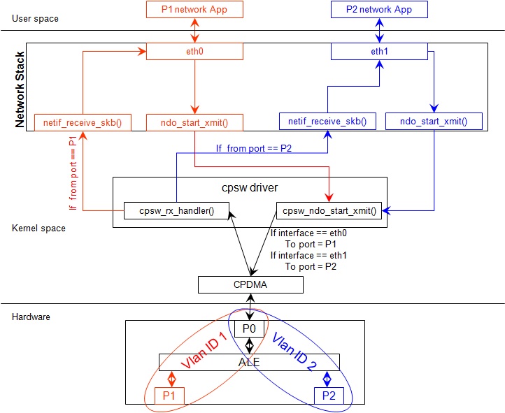
Assumptions
- Interrupt source is common for both eth interfaces
- CPDMA and skb buffers are common for both eth interfaces
- If eth0 is up, then eth0 napi is used. eth1 napi is used when eth0 interface is down
- CPSW and ALE will be in VLAN aware mode irrespective of enabling of 802.1Q module in Linux network stack for adding port VLAN.
- Interrupt pacing is common for both interfaces
- Hardware statistics is common for all the ports
- Switch config will not be available in dual emac interface mode
Constraints
The following are the constrains for Dual Emac mode implementation
- VLAN id 1 and 2 are reserved for EMAC 0 and 1 respectively for port segregation
- Port vlans mentioned in dts file are reserved and should not be added to cpsw through vconfig as it violate the Dual EMAC implementation and switch mode will be enabled.
- While adding VLAN id to the eth interfaces, same VLAN id should not be added in both interfaces which will lead to VLAN forwarding and act as switch
- Manual ip for eth1 is not supported from Linux kernel arguments
- Both the interfaces should not be connected to the same subnet unless only configuring bridging, and not doing IP routing, then you can configure the two interfaces on the same subnet.
Dual EMAC Device tree entry
Dual EMAC can be enabled with adding the entry dual_emac to the cpsw device tree node as the reference patch below
diff --git a/arch/arm/boot/dts/am335x-evmsk.dts b/arch/arm/boot/dts/am335x-evmsk.dts
index ac1f759..b50e9ef 100644
--- a/arch/arm/boot/dts/am335x-evmsk.dts
+++ b/arch/arm/boot/dts/am335x-evmsk.dts
@@ -473,6 +473,7 @@
        pinctrl-names = "default", "sleep";
        pinctrl-0 = <&cpsw_default>;
        pinctrl-1 = <&cpsw_sleep>;
+       dual_emac;
 };

 &davinci_mdio {
@@ -484,11 +485,13 @@
 &cpsw_emac0 {
        phy_id = <&davinci_mdio>, <0>;
        phy-mode = "rgmii-txid";
+       dual_emac_res_vlan = <1>;
 };

 &cpsw_emac1 {
        phy_id = <&davinci_mdio>, <1>;
        phy-mode = "rgmii-txid";
+       dual_emac_res_vlan = <2>;
 };
Bringing Up interfaces
Eth0 will be up by-default. Eth1 interface has to be brought up manually using either of the folloing command or through init scripts
DHCP
ifup eth1
Manual IP address configuration
ifconfig eth1 <ip> netmask <mask> up
Primary Interface on Second External Port
There are some pin mux configurations on devices that use the CPSW 3P such as the AM335x, AM437x, AM57x and others that to enable Ethernet requires using the second external port as the primary interface. Here is a suggested DTS configuration when using the second port.
The key step is setting the active_slave flag to 1 in the MAC node of the board DTS, this tells the driver to use the second interface as primary in a single MAC configuration. The cpsw1 relates to the physical port and not the Ethernet device. Also make sure to remove the dual mac flag. This example configuration will still yield eth0 in the network interface list.
Please note this is an example for the AM335x, the PHY mode below will set tx internal delay (rgmii-txid) which is required for AM335x devices. Please consult example DTS files for the AM437x and AM57x EVMs for respective PHY modes.
&mac {
       pinctrl-names = "default", "sleep";
       pinctrl-0 = <&cpsw_default>;
       pinctrl-1 = <&cpsw_sleep>;
       active_slave = <1>;
       status = "okay";
};

&davinci_mdio {
       pinctrl-names = "default", "sleep";
       pinctrl-0 = <&davinci_mdio_default>;
       pinctrl-1 = <&davinci_mdio_sleep>;
       status = "okay";
};

&cpsw_emac1 {
       phy_id = <&davinci_mdio>, <1>;
       phy-mode = "rgmii-txid";
};
Switch Configuration Interface
Introduction
The CPSW Ethernet Switch can be configured in various different combination of Ethernet Packet forwarding and blocking. There is no such standard interface in Linux to configure a switch. This user guide provides an interface to configure the switch using Socket IOCTL through SIOCSWITCHCONFIG command.
Configuring Kernel with VLAN Support
Userspace binary formats —>
    Power management options  --->
[*] Networking support  --->
    Device Drivers  --->
    File systems  --->
    Kernel hacking  --->
--- Networking support
      Networking options  --->
[ ]   Amateur Radio support  --->
<*>   CAN bus subsystem support  --->
< >   IrDA (infrared) subsystem support  --->
< >   Bluetooth subsystem support  --->
< >   RxRPC session sockets
< > The RDS Protocol (EXPERIMENTAL)
< > The TIPC Protocol (EXPERIMENTAL)  --->
< > Asynchronous Transfer Mode (ATM)
< > Layer Two Tunneling Protocol (L2TP)  --->
< > 802.1d Ethernet Bridging
[ ] Distributed Switch Architecture support  --->
<*> 802.1Q VLAN Support
[*]   GVRP (GARP VLAN Registration Protocol) support
< > DECnet Support
< > ANSI/IEEE 802.2 LLC type 2 Support
< > The IPX protocol
Switch Config Commands
Following is sample code for configuring the switch.
#include <stdio.h>
...
#include <linux/net_switch_config.h>
int main(void)
{
    struct net_switch_config cmd_struct;
    struct ifreq ifr;
    int sockfd;
    strncpy(ifr.ifr_name, "eth0", IFNAMSIZ);
    ifr.ifr_data = (char*)&cmd_struct;
    if ((sockfd = socket(AF_INET, SOCK_DGRAM, 0)) < 0) {
        printf("Can't open the socket\n");
        return -1;
    }
    memset(&cmd_struct, 0, sizeof(struct net_switch_config));

    ...//initialise cmd_struct with switch commands

    if (ioctl(sockfd, SIOCSWITCHCONFIG, &ifr) < 0) {
        printf("Command failed\n");
        close(sockfd);
        return -1;
    }
    printf("command success\n");
    close(sockfd);
    return 0;
}
CONFIG_SWITCH_ADD_MULTICAST
CONFIG_SWITCH_ADD_MULTICAST is used to add a LLDP Multicast address and forward the multicast packet to the subscribed ports. If VLAN ID is greater than zero then VLAN LLDP/Multicast is added.
cmd_struct.cmd = CONFIG_SWITCH_ADD_MULTICAST
| Parameter | Description | Range |
|---|---|---|
| cmd_struct.addr | LLDP/Multicast Address | MAC Address |
| cmd_struct.port | Member port | Bit 0 – Host port/Port 0 | Bit 1 – Slave 0/Port 1 | Bit 2 – Slave 1/Port 2 | 0 – 7 |
| cmd_struct.vid | VLAN ID | 0 – 4095 |
| cmd_struct.super | Super | 0/1 |
Result
ioctl call returns success or failure.
CONFIG_SWITCH_DEL_MULTICAST
CONFIG_SWITCH_DEL_MULTICAST is used to Delete a LLDP/Multicast address with or without VLAN ID.
cmd_struct.cmd = CONFIG_SWITCH_DEL_MULTICAST
| Parameter | Description | Range |
|---|---|---|
| cmd_struct.addr | Unicast Address | MAC Address |
| cmd_struct.vid | VLAN ID | 0 – 4095 |
Result
ioctl call returns success or failure.
CONFIG_SWITCH_ADD_VLAN
CONFIG_SWITCH_ADD_VLAN is used to add VLAN ID.
cmd_struct.cmd = CONFIG_SWITCH_ADD_VLAN
| Parameter | Description | Range |
|---|---|---|
| cmd_struct.vid | VLAN ID | 0 – 4095 |
| cmd_struct.port | Member port | Bit 0 – Host port/Port 0 | Bit 1 – Slave 0/Port 1 | Bit 2 – Slave 1/Port 2 | 0 – 7 |
| cmd_struct.untag_port | Untagged Egress port mask | Bit 0 – Host port/Port 0 | Bit 1 – Slave 0/Port 1 | Bit 2 – Slave 1/Port 2 | 0 – 7 |
| cmd_struct.reg_multi | Registered Multicast flood port mask | Bit 0 – Host port/Port 0 | Bit 1 – Slave 0/Port 1 | Bit 2 – Slave 1/Port 2 | 0 – 7 |
| cmd_struct.unreg_multi | Unknown Multicast flood port mask | Bit 0 – Host port/Port 0 | Bit 1 – Slave 0/Port 1 | Bit 2 – Slave 1/Port 2 | 0 – 7 |
Result
ioctl call returns success or failure.
CONFIG_SWITCH_DEL_VLAN
CONFIG_SWITCH_DEL_VLAN is used to delete VLAN ID.
cmd_struct.cmd = CONFIG_SWITCH_DEL_VLAN
| Parameter | Description | Range |
|---|---|---|
| cmd_struct.vid | VLAN ID | 0 – 4095 |
Result
ioctl call returns success or failure.
CONFIG_SWITCH_ADD_UNKNOWN_VLAN_INFO
CONFIG_SWITCH_ADD_UNKNOWN_VLAN_INFO is used to set unknown VLAN Info.
cmd_struct.cmd = CONFIG_SWITCH_ADD_UNKNOWN_VLAN_INFO
| Parameter | Description | Range |
|---|---|---|
| cmd_struct.unknown_vla n_member | Port mask | Bit 0 – Host port/Port 0 | Bit 1 – Slave 0/Port 1 | Bit 2 – Slave 1/Port 2 | 0 - 7 |
| cmd_struct.unknown_vla n_reg_multi | Registered Multicast flood port mask | Bit 0 – Host port/Port 0 | Bit 1 – Slave 0/Port 1 | Bit 2 – Slave 1/Port 2 | 0 - 7 |
| cmd_struct.unknown_vla n_unreg_multi | Unknown Multicast flood port mask | Bit 0 – Host port/Port 0 | Bit 1 – Slave 0/Port 1 | Bit 2 – Slave 1/Port 2 | 0 - 7 |
| cmd_struct.unknown_vla n_untag | Unknown Vlan Member port mask | Bit 0 – Host port/Port 0 | Bit 1 – Slave 0/Port 1 | Bit 2 – Slave 1/Port 2 | 0 - 7 |
Result
ioctl call returns success or failure.
CONFIG_SWITCH_SET_PORT_CONFIG
CONFIG_SWITCH_SET_PORT_CONFIG is used to set Phy Config.
cmd_struct.cmd = CONFIG_SWITCH_SET_PORT_CONFIG
| Parameter | Description | Range |
|---|---|---|
| cmd_struct.port | Port number | 0 - 2 |
| cmd_struct.ecmd | Phy settings | Fill this structure (struct ethtool_cmd), refer file include/uapi/linux/ethtool.h |
Result
ioctl call returns success or failure.
CONFIG_SWITCH_GET_PORT_CONFIG
CONFIG_SWITCH_GET_PORT_CONFIG is used to get Phy Config.
cmd_struct.cmd = CONFIG_SWITCH_GET_PORT_CONFIG
| Parameter | Description | Range |
|---|---|---|
| cmd_struct.port | Port number | 0 - 2 |
Result
ioctl call returns success or failure.
On success “cmd_struct.ecmd” holds port phy settings
CONFIG_SWITCH_SET_PORT_STATE
CONFIG_SWITCH_SET_PORT_STATE is used to set port status.
cmd_struct.cmd = CONFIG_SWITCH_SET_PORT_STATE
| Parameter | Description | Range |
|---|---|---|
| cmd_struct.port | Port number | 0 - 2 |
| cmd_struct.port_state | Port state | PORT_STATE_DISABLED/ PORT_STATE_BLOCKED/ PORT_STATE_LEARN/ PORT_STATE_FORWARD |
Result
ioctl call returns success or failure.
CONFIG_SWITCH_GET_PORT_STATE
CONFIG_SWITCH_GET_PORT_STATE is used to set port status.
cmd_struct.cmd = CONFIG_SWITCH_GET_PORT_STATE
| Parameter | Description | Range |
|---|---|---|
| cmd_struct.port | Port number | 0 - 2 |
Result
ioctl call returns success or failure.
On success “cmd_struct.port_state” holds port state
CONFIG_SWITCH_RATELIMIT
CONFIG_SWITCH_RATELIMIT is used to enable/disable rate limit of the ports.
The MC/BC Rate limit feature filters of BC/MC packets per sec as following:
number_of_packets/sec = (Fclk / ALE_PRESCALE) * port.BCAST/MCAST_LIMIT
where: ALE_PRESCALE width is 19bit and min value 0x10.
Each ALE prescale pulse loads port.BCAST/MCAST_LIMIT into the port MC/BC rate limit counter and port counters are decremented with each packet received or transmitted depending on whether the mode is transmit or receive. ALE prescale pulse frequency detrmined by ALE_PRESCALE register.
with Fclk = 125MHz and port.BCAST/MCAST_LIMIT = 1
max number_of_packets/sec = (125MHz / 0x10) * 1 = 7 812 500
min number_of_packets/sec = (125MHz / 0xFFFFF) * 1 = 119
So port.BCAST/MCAST_LIMIT can be selected to be 1 while ALE_PRESCALE is calculated as:
ALE_PRESCALE = Fclk / number_of_packets
cmd\_struct.cmd = CONFIG\_SWITCH\_RATELIMIT
| Parameter | Description | Range |
|---|---|---|
| cmd_struct.direction | Transmit/Receive | Transmit - 1 Receive - 0 |
| cmd_struct.port | Port number | 0 - 2 |
| cmd_struct.bcast_rate_limit | Broadcast, No of Packet | number_of_packets/sec |
| cmd_struct.mcast_rate_limit | Multicast, No of Packet | number_of_packets/sec |
Result
ioctl call returns success or failure.
Switch config ioctl mapping with v3.2
This section is applicable only to whom are migrating from v3.2 to v3.14 for am335x.
| v3.2 ioctl | Method in v3.14 | Comments |
|---|---|---|
| CONFIG_SWITCH_ADD_MULTICAST | CONFIG_SWITCH_ADD_MULTICAST | |
| CONFIG_SWITCH_ADD_UNICAST | Deprecated | Not supported as switch can learn by ingress packet |
| CONFIG_SWITCH_ADD_OUI | Deprecated | |
| CONFIG_SWITCH_FIND_ADDR | Deprecated | Address can be searched via ethtool -d ethX or switch-config -d,--dump |
| CONFIG_SWITCH_DEL_MULTICAST | CONFIG_SWITCH_DEL_MULTICAST | |
| CONFIG_SWITCH_DEL_UNICAST | Deprecated | |
| CONFIG_SWITCH_ADD_VLAN | CONFIG_SWITCH_ADD_VLAN | |
| CONFIG_SWITCH_FIND_VLAN | Deprecated | Address can be searched via ethtool -d ethX or switch-config -d,--dump |
| CONFIG_SWITCH_DEL_VLAN | CONFIG_SWITCH_DEL_VLAN | |
| CONFIG_SWITCH_SET_PORT_VLAN_CONFIG | CONFIG_SWITCH_SET_PORT_VLAN_CONFIG | |
| CONFIG_SWITCH_TIMEOUT | Deprecated | There is no hardware timers, a software timer of 10S is used to clear untouched entries in ALE table. |
| CONFIG_SWITCH_DUMP | Deprecated | Address can be searched via ethtool -d ethX or switch-config -d,--dump |
| CONFIG_SWITCH_SET_FLOW_CONTROL | Deprecated | Address can be searched via ethtool -A ethX <parameters> |
| CONFIG_SWITCH_SET_PRIORITY_MAPPING | Deprecated | |
| CONFIG_SWITCH_PORT_STATISTICS_ENABLE | Deprecated | statistics is enabled for all ports by default |
| CONFIG_SWITCH_CONFIG_DUMP | Deprecated | Address can be searched via ethtool -S ethX |
| CONFIG_SWITCH_RATELIMIT | CONFIG_SWITCH_RATELIMIT | |
| CONFIG_SWITCH_VID_INGRESS_CHECK | Deprecated | |
| CONFIG_SWITCH_ADD_UNKNOWN_VLAN_INFO | CONFIG_SWITCH_ADD_UNKNOWN_VLAN_INFO | |
| CONFIG_SWITCH_802_1 | Deprecated | Can be achecived by adding respective multicast address using CONFIG_SWITCH_ADD_MULTICAST |
| CONFIG_SWITCH_MACAUTH | Deprecated | |
| CONFIG_SWITCH_SET_PORT_CONFIG | CONFIG_SWITCH_SET_PORT_CONFIG | |
| CONFIG_SWITCH_GET_PORT_CONFIG | CONFIG_SWITCH_GET_PORT_CONFIG | |
| CONFIG_SWITCH_PORT_STATE | CONFIG_SWITCH_GET_PORT_STATE/ CONFIG_SWITCH_SET_PORT_STATE | |
| CONFIG_SWITCH_RESET | Deprecated | Close the interface and open the interface again which will reset the switch by default. |
ethtool - Display or change ethernet card settings
ethtool DEVNAME Display standard information about device
# ethtool eth0
Settings for eth0:
Supported ports: [ TP MII ]
Supported link modes:   10baseT/Half 10baseT/Full
                        100baseT/Half 100baseT/Full
                        1000baseT/Half 1000baseT/Full
Supported pause frame use: Symmetric
Supports auto-negotiation: Yes
Advertised link modes:  10baseT/Half 10baseT/Full
                        100baseT/Half 100baseT/Full
                        1000baseT/Half 1000baseT/Full
Advertised pause frame use: Symmetric
Advertised auto-negotiation: Yes
Link partner advertised link modes:  10baseT/Half 10baseT/Full
                                     100baseT/Half 100baseT/Full
                                     1000baseT/Full
Link partner advertised pause frame use: Symmetric
Link partner advertised auto-negotiation: Yes
Speed: 1000Mb/s
Duplex: Full
Port: MII
PHYAD: 1
Transceiver: external
Auto-negotiation: on
Supports Wake-on: d
Wake-on: d
Current message level: 0x00000000 (0)
Link detected: yes"
ethtool -i|–driver DEVNAME Show driver information
#ethtool -i eth0
driver: cpsw
version: 1.0
firmware-version:
expansion-rom-version:
bus-info: 48484000.ethernet
supports-statistics: yes
supports-test: no
supports-eeprom-access: no
supports-register-dump: yes
supports-priv-flags: no"
ethtool -P|–show-permaddr DEVNAME Show permanent hardware address
# ethtool -P eth0
Permanent address: a0:f6:fd:a6:46:6e"
ethtool -s|–change DEVNAME Change generic options
Below commands will be redirected to the phy driver:
[ speed %d ]
[ duplex half|full ]
[ autoneg on|off ]
[ wol p|u|m|b|a|g|s|d... ]
[ sopass %x:%x:%x:%x:%x:%x ]
Note
CPSW driver do not perform any kind of WOL specific actions or configurations.
#ethtool -s eth0 duplex half speed 100
[ 3550.892112] cpsw 48484000.ethernet eth0: Link is Down
[ 3556.088704] cpsw 48484000.ethernet eth0: Link is Up - 100Mbps/Half - flow control off
Sets the driver message type flags by name or number
[ msglvl %d | msglvl type on|off ... ]
# ethtool -s eth0 msglvl drv off
# ethtool -s eth0 msglvl ifdown off
# ethtool -s eth0 msglvl ifup off
# ethtool eth0
Current message level: 0x00000031 (49)
                       drv ifdown ifup
ethtool -r|–negotiate DEVNAME Restart N-WAY negotiation
# ethtool -r eth0
[ 4338.167685] cpsw 48484000.ethernet eth0: Link is Down
[ 4341.288695] cpsw 48484000.ethernet eth0: Link is Up - 1Gbps/Full - flow control rx/tx"
ethtool -a|–show-pause DEVNAME Show pause options
# ethtool -a eth0
Pause parameters for eth0:
Autonegotiate:  off
RX:             off
TX:             off
ethtool -A|–pause DEVNAME Set pause options
# ethtool -A eth0 rx on tx on
cpsw 48484000.ethernet eth0: Link is Up - 1Gbps/Full - flow control rx/tx
# ethtool -a eth0
Pause parameters for eth0:
Autonegotiate:  off
RX:             on
TX:             on
ethtool -C|–coalesce DEVNAME Set coalesce options
[rx-usecs N]
See [“Interrupt Pacing”] section for more information”
# ethtool -C eth0 rx-usecs 500
ethtool -c|–show-coalesce DEVNAME Show coalesce options
# ethtool -c eth0
Coalesce parameters for eth0:
Adaptive RX: off  TX: off
stats-block-usecs: 0
sample-interval: 0
pkt-rate-low: 0
pkt-rate-high: 0
rx-usecs: 0
rx-frames: 0
rx-usecs-irq: 0
rx-frames-irq: 0
tx-usecs: 0
tx-frames: 0
tx-usecs-irq: 0
tx-frames-irq: 0
rx-usecs-low: 0
rx-frame-low: 0
tx-usecs-low: 0
tx-frame-low: 0
rx-usecs-high: 0
rx-frame-high: 0
tx-usecs-high: 0
Tx-frame-high: 0
ethtool -G|–set-ring DEVNAME Set RX/TX ring parameters
Supported options:
[ rx N ]
See [“Configure number of TX/RX descriptors”] section for more information
# ethtool -G eth0 rx 8000
ethtool -g|–show-ring DEVNAME Query RX/TX ring parameters
# ethtool -g eth0
Ring parameters for eth0:
Pre-set maximums:
RX:             8184
RX Mini:        0
RX Jumbo:       0
TX:             0
Current hardware settings:
RX:             8000
RX Mini:        0
RX Jumbo:       0
TX:             192
ethtool -d|–register-dump DEVNAME Do a register dump
This command will dump current ALE table
# ethtool -d eth0
Offset          Values
------          ------
0x0000:         00 00 00 00 00 00 02 20 05 00 05 05 14 00 00 00
0x0010:         ff ff 02 30 ff ff ff ff 01 00 00 00 da 74 02 30
0x0020:         b9 83 48 ea 00 00 00 00 00 00 00 20 07 00 00 07
0x0030:         14 00 00 00 00 01 02 30 01 00 00 5e 0c 00 00 00
0x0040:         33 33 01 30 01 00 00 00 00 00 00 00 00 00 01 20
0x0050:         03 00 03 03 0c 00 00 00 ff ff 01 30 ff ff ff ff
ethtool -S|–statistics DEVNAME Show adapter statistics
# ethtool -S eth0
NIC statistics:
   Good Rx Frames: 24
   Broadcast Rx Frames: 12
   Multicast Rx Frames: 4
   Pause Rx Frames: 0
   Rx CRC Errors: 0
   Rx Align/Code Errors: 0
   Oversize Rx Frames: 0
   Rx Jabbers: 0
   Undersize (Short) Rx Frames: 0
   Rx Fragments: 1
   Rx Octets: 4290
   Good Tx Frames: 379
   Broadcast Tx Frames: 144
   Multicast Tx Frames: 228
   Pause Tx Frames: 0
   Deferred Tx Frames: 0
   Collisions: 0
   Single Collision Tx Frames: 0
   Multiple Collision Tx Frames: 0
   Excessive Collisions: 0
   Late Collisions: 0
   Tx Underrun: 0
   Carrier Sense Errors: 0
   Tx Octets: 72498
   Rx + Tx 64 Octet Frames: 30
   Rx + Tx 65-127 Octet Frames: 218
   Rx + Tx 128-255 Octet Frames: 0
   Rx + Tx 256-511 Octet Frames: 155
   Rx + Tx 512-1023 Octet Frames: 0
   Rx + Tx 1024-Up Octet Frames: 0
   Net Octets: 76792
   Rx Start of Frame Overruns: 0
   Rx Middle of Frame Overruns: 0
   Rx DMA Overruns: 0
   Rx DMA chan 0: head_enqueue: 2
   Rx DMA chan 0: tail_enqueue: 12114
   Rx DMA chan 0: pad_enqueue: 0
   Rx DMA chan 0: misqueued: 0
   Rx DMA chan 0: desc_alloc_fail: 0
   Rx DMA chan 0: pad_alloc_fail: 0
   Rx DMA chan 0: runt_receive_buf: 0
   Rx DMA chan 0: runt_transmit_bu: 0
   Rx DMA chan 0: empty_dequeue: 0
   Rx DMA chan 0: busy_dequeue: 14
   Rx DMA chan 0: good_dequeue: 21
   Rx DMA chan 0: requeue: 1
   Rx DMA chan 0: teardown_dequeue: 4095
   Tx DMA chan 0: head_enqueue: 378
   Tx DMA chan 0: tail_enqueue: 1
   Tx DMA chan 0: pad_enqueue: 0
   Tx DMA chan 0: misqueued: 1
   Tx DMA chan 0: desc_alloc_fail: 0
   Tx DMA chan 0: pad_alloc_fail: 0
   Tx DMA chan 0: runt_receive_buf: 0
   Tx DMA chan 0: runt_transmit_bu: 26
   Tx DMA chan 0: empty_dequeue: 379
   Tx DMA chan 0: busy_dequeue: 0
   Tx DMA chan 0: good_dequeue: 379
   Tx DMA chan 0: requeue: 0
   Tx DMA chan 0: teardown_dequeue: 0"
ethtool –phy-statistics DEVNAME Show phy statistics
ethtool -T|–show-time-stamping DEVNAME Show time stamping capabilities.
Accessible when CPTS is enabled.
# ethtool -T eth0
Time stamping parameters for eth0:
Capabilities:
        hardware-transmit     (SOF_TIMESTAMPING_TX_HARDWARE)
        software-transmit     (SOF_TIMESTAMPING_TX_SOFTWARE)
        hardware-receive      (SOF_TIMESTAMPING_RX_HARDWARE)
        software-receive      (SOF_TIMESTAMPING_RX_SOFTWARE)
        software-system-clock (SOF_TIMESTAMPING_SOFTWARE)
        hardware-raw-clock    (SOF_TIMESTAMPING_RAW_HARDWARE)
PTP Hardware Clock: 0
Hardware Transmit Timestamp Modes:
        off                   (HWTSTAMP_TX_OFF)
        on                    (HWTSTAMP_TX_ON)
Hardware Receive Filter Modes:
        none                  (HWTSTAMP_FILTER_NONE)
        ptpv2-event           (HWTSTAMP_FILTER_PTP_V2_EVENT)"
ethtool -L|–set-channels DEVNAME Set Channels.
Supported options:
[ rx N ]
[ tx N ]
Allows to control number of channels driver is allowed to work with at cpdma level. The maximum number of channels is 8 for rx and 8 for tx. In dual_emac mode the h/w channels are shared between two interfaces and changing number on one interface changes number of channels on another.
# ethtool -L eth0 rx 6 tx 6
ethtool-l|–show-channels DEVNAME Query Channels
# ethtool -l eth0
Channel parameters for eth0:
Pre-set maximums:
RX:             8
TX:             8
Other:          0
Combined:       0
Current hardware settings:
RX:             6
TX:             6
Other:          0
Combined:       0
ethtool –show-eee DEVNAME Show EEE settings
#ethtool --show-eee eth0
EEE Settings for eth0:
        EEE status: not supported
ethtool –set-eee DEVNAME Set EEE settings.
Note
Full EEE is not supported in cpsw driver, but it enables reading and writing of EEE advertising settings in Ethernet PHY. This way one can disable advertising EEE for certain speeds.
Realtime Linux Kernel Network performance
The significant network throughput drop is observed on SMP platforms with RT kernel (ti-rt-linux-4.9.y). There are few possible ways to improve network throughput on RT:
1) assign network interrupts to only one CPU (both RX/TX IRQ can be assigned to CPUx, or RX can be assigne to CPU0 and TX to CPU1) using cpu affinity settings:
am57xx-evm:~# cat /proc/interrupts
353:     518675          0      CBAR 335 Level     48484000.ethernet
354:    1468516          0      CBAR 336 Level     48484000.ethernet
assign both handlers to CPU1:
am57xx-evm:~#echo 2 > /proc/irq/354/smp_affinity
am57xx-evm:~#echo 2 > /proc/irq/353/smp_affinity
before:
am57xx-evm:~# iperf -c 192.168.1.1 -w128K -d -i5 -t120 & cyclictest -n -m -Sp97 -q -D2m
    ------------------------------------------------------------
    Server listening on TCP port 5001
    TCP window size:  256 KByte (WARNING: requested  128 KByte)
    ------------------------------------------------------------
    ------------------------------------------------------------
    Client connecting to 192.168.1.1, TCP port 5001
    TCP window size:  256 KByte (WARNING: requested  128 KByte)
    ------------------------------------------------------------
    [  5]  0.0-120.0 sec  2.16 GBytes   154 Mbits/sec
    [  4]  0.0-120.0 sec  5.21 GBytes   373 Mbits/sec
    T: 0 ( 1074) P:97 I:1000 C: 120000 Min:      8 Act:    9 Avg:   17 Max:      53
    T: 1 ( 1075) P:97 I:1500 C:  79982 Min:      8 Act:    9 Avg:   17 Max:      60
after:
am57xx-evm:~# iperf -c 192.168.1.1 -w128K -d -i5 -t120 & cyclictest -n -m -Sp97 -q -D2m
    ------------------------------------------------------------
    Server listening on TCP port 5001
    TCP window size:  256 KByte (WARNING: requested  128 KByte)
    ------------------------------------------------------------
    ------------------------------------------------------------
    Client connecting to 192.168.1.1, TCP port 5001
    TCP window size:  256 KByte (WARNING: requested  128 KByte)
    ------------------------------------------------------------
    [  5] local 192.168.1.2 port 35270 connected with 192.168.1.1 port 5001
    [  4] local 192.168.1.2 port 5001 connected with 192.168.1.1 port 55703
    [ ID] Interval       Transfer     Bandwidth
    [  5]  0.0-120.0 sec  4.58 GBytes   328 Mbits/sec
    [  4]  0.0-120.0 sec  4.88 GBytes   349 Mbits/sec
    T: 0 ( 1080) P:97 I:1000 C: 120000 Min:      9 Act:    9 Avg:   17 Max:      38
    T: 1 ( 1081) P:97 I:1500 C:  79918 Min:      9 Act:   16 Avg:   14 Max:      37
2) make CPSW network interrupts handlers non threaded. This requires kernel modification as done in:
[drivers: net: cpsw: mark rx/tx irq as IRQF_NO_THREAD]
See allso public discussion:
https://www.spinics.net/lists/netdev/msg389697.html
after:
am57xx-evm:~# iperf -c 192.168.1.1 -w128K -d -i5 -t120 & cyclictest -n -m -Sp97 -q - D2m
    ------------------------------------------------------------
    Server listening on TCP port 5001
    TCP window size:  256 KByte (WARNING: requested  128 KByte)
    ------------------------------------------------------------
    ------------------------------------------------------------
    Client connecting to 192.168.1.1, TCP port 5001
    TCP window size:  256 KByte (WARNING: requested  128 KByte)
    ------------------------------------------------------------
    [  5] local 192.168.1.2 port 33310 connected with 192.168.1.1 port 5001
    [  4] local 192.168.1.2 port 5001 connected with 192.168.1.1 port 55704
    [ ID] Interval       Transfer     Bandwidth
    [  5]  0.0-120.0 sec  3.72 GBytes   266 Mbits/sec
    [  4]  0.0-120.0 sec  5.99 GBytes   429 Mbits/sec
    T: 0 ( 1083) P:97 I:1000 C: 120000 Min:      8 Act:    9 Avg:   15 Max:      39
    T: 1 ( 1084) P:97 I:1500 C:  79978 Min:      8 Act:   10 Avg:   17 Max:      39
3.3.4.13.2. Common Platform Time Sync (CPTS) module
The Common Platform Time Sync (CPTS) module is used to facilitate host control of time sync operations. It enables compliance with the IEEE 1588-2008 standard for a precision clock synchronization protocol.
The support for CPTS module can be enabled by Kconfig option CONFIG_TI_CPTS=y or through menuconfig tool. The PTP packet timestamping can be enabled only for one CPSW port.
When CPTS module is enabled it will exports a kernel interface for specific clock drivers and a PTP clock API user space interface and enable support for SIOCSHWTSTAMP and SIOCGHWTSTAMP socket ioctls. The PTP exposes the PHC as a character device with standardized ioctls which usially can be found at path:
/dev/ptp0
Supported PTP hardware clock functionality:
Basic clock operations
   - Set time
   - Get time
   - Shift the clock by a given offset atomically
   - Adjust clock frequency
Ancillary clock features
   - Time stamp external events
   NOTE. Current implementation supports ext events with max frequency 5HZ.
Supported parameters for SIOCSHWTSTAMP and SIOCGHWTSTAMP:
SIOCGHWTSTAMP
   hwtstamp_config.flags = 0
   hwtstamp_config.tx_type
       HWTSTAMP_TX_ON
       HWTSTAMP_TX_OFF
   hwtstamp_config.rx_filter
       HWTSTAMP_FILTER_PTP_V2_EVENT
       HWTSTAMP_FILTER_NONE
SIOCSHWTSTAMP
   hwtstamp_config.flags = 0
   hwtstamp_config.tx_type
       HWTSTAMP_TX_ON - enables hardware time stamping for outgoing packets
       HWTSTAMP_TX_OFF - no outgoing packet will need hardware time stamping
   hwtstamp_config.rx_filter
       HWTSTAMP_FILTER_NONE - time stamp no incoming packet at all
HWTSTAMP_FILTER_PTP_V2_L4_EVENT
HWTSTAMP_FILTER_PTP_V2_L4_SYNC
HWTSTAMP_FILTER_PTP_V2_L4_DELAY_REQ
HWTSTAMP_FILTER_PTP_V2_L2_EVENT
HWTSTAMP_FILTER_PTP_V2_L2_SYNC
HWTSTAMP_FILTER_PTP_V2_L2_DELAY_REQ
HWTSTAMP_FILTER_PTP_V2_EVENT
HWTSTAMP_FILTER_PTP_V2_SYNC
HWTSTAMP_FILTER_PTP_V2_DELAY_REQ
- all above filters will enable timestamping of incoming PTP v2/802.AS1
  packets, any layer, any kind of event packet
CPTS PTP packet timestamping default configuration when enabled (SIOCSHWTSTAMP):
CPSW SS CPSW_VLAN_LTYPE register:
TS_LTYPE2 = 0
    Time Sync LTYPE2 This is an Ethertype value to match for tx and rx time sync packets.
TS_LTYPE1 = 0x88F7 (ETH_P_1588)
    Time Sync LTYPE1 This is an ethertype value to match for tx and rx time sync packets.
Port registers: Pn_CONTROL Register:
Pn_TS_107 Port n Time Sync Destination IP Address 107 enable
                0 – disabled
Pn_TS_320 Port n Time Sync Destination Port Number 320 enable
                1 - Annex D (UDP/IPv4) time sync packet destination port
                number 320 (decimal) is enabled.
Pn_TS_319 Port n Time Sync Destination Port Number 319 enable
                1 - Annex D (UDP/IPv4) time sync packet destination port
                number 319 (decimal) is enabled.
Pn_TS_132 Port n Time Sync Destination IP Address 132 enable
                1 - Annex D (UDP/IPv4) time sync packet destination IP
                address number 132 (decimal) is enabled.
Pn_TS_131 - Port 1 Time Sync Destination IP Address 131 enable
                1 - Annex D (UDP/IPv4) time sync packet destination IP
                address number 131 (decimal) is enabled.
Pn_TS_130 Port n Time Sync Destination IP Address 130 enable
                1 - Annex D (UDP/IPv4) time sync packet destination IP
                address number 130 (decimal) is enabled.
Pn_TS_129 Port n Time Sync Destination IP Address 129 enable
                1 - Annex D (UDP/IPv4) time sync packet destination IP
                address number 129 (decimal) is enabled.
Pn_TS_TTL_NONZERO Port n Time Sync Time To Live Non-zero enable.
                1 = TTL may be any value.
Pn_TS_UNI_EN Port n Time Sync Unicast Enable
                0 – Unicast disabled
Pn_TS_ANNEX_F_EN Port n Time Sync Annex F enable
                1 – Annex F enabled
Pn_TS_ANNEX_E_EN Port n Time Sync Annex E enable
                0 – Annex E disabled
Pn_TS_ANNEX_D_EN Port n Time Sync Annex D enable
                1 - Annex D enabled RW 0x0
Pn_TS_LTYPE2_EN Port n Time Sync LTYPE 2 enable
                0 - disabled
Pn_TS_LTYPE1_EN Port n Time Sync LTYPE 1 enable
                1 - enabled
Pn_TS_TX_EN Port n Time Sync Transmit Enable
                1 - enabled (if HWTSTAMP_TX_ON)
Pn_TS_RX_EN Port n Time Sync Receive Enable
                1 - Port 1 Receive Time Sync enabled (if HWTSTAMP_FILTER_PTP_V2_X)
Pn_TS_SEQ_MTYPE Register:
Pn_TS_SEQ_ID_OFFSET = 0x1E
Port n Time Sync Sequence ID Offset This is the number
of octets that the sequence ID is offset in the tx and rx
time sync message header. The minimum value is 6. RW 0x1E
Pn_TS_MSG_TYPE_EN = 0xF (Sync, Delay_Req, Pdelay_Req, and Pdelay_Resp.)
Port n Time Sync Message Type Enable - Each bit in this
field enables the corresponding message type in receive
and transmit time sync messages (Bit 0 enables message type 0 etc.).
For more information about PTP clock API and Network timestamping see Linux kernel documentation Documentation/ptp/ptp.txt
include/uapi/linux/ptp_clock.h
Documentation/ABI/testing/sysfs-ptp
tools/testing/selftests/networking/timestamping/timestamping.c
Testing using ptp4l tool from linuxptp project
To check the ptp clock adjustment with PTP protocol, a PTP slave (client) and a PTP master (server) applications are needed to run on separate devices (EVM or PC). Open source application package linuxptp can be used as slave and as well as master. Hence TX timestamp generation can be delayed (especially with low speed links) the ptp4l “tx_timestamp_timeout” parameter need to be set for ptp4l to work.
- create file ptp.cfg with content as below:
[global]
tx_timestamp_timeout 400
- pass configuration file to ptp4l using “-f” option:
ptp4l -E -2 -H -i eth0 -l 6 -m -q -p /dev/ptp0 -f ptp.cfg
- Slave Side Examples
The following command can be used to run a ptp-over-L4 client on the evm in slave mode
./ptp4l -E -4 -H -i eth0 -s -l 7 -m -q -p /dev/ptp0
For ptp-over-L2 client, use the command
./ptp4l -E -2 -H -i eth0 -s -l 7 -m -q -p /dev/ptp0
- Master Side Examples
ptp4l can also be run in master mode. For example, the following command starts a ptp4l-over-L2 master on an EVM using hardware timestamping,
./ptp4l -E -2 -H -i eth0 -l 7 -m -q -p /dev/ptp0
On a Linux PC which does not supoort hardware timestamping, the following command starts a ptp4l-over-L2 master using software timestamping.
./ptp4l -E -2 -S -i eth0 -l 7 -m -q
Testing using testptp tool from Linux kernel
- get the ptp clock time
# testptp -g
clock time: 1493255613.608918429 or Thu Apr 27 01:13:33 2017
- query the ptp clock’s capabilities
# testptp -c
capabilities:
1000000 maximum frequency adjustment (ppb)
0 programmable alarms
0 external time stamp channels
0 programmable periodic signals
0 pulse per second
0 programmable pins
- Sanity testing of cpts ref frequency
Time difference between to testptp -g calls should be equal sleep time
# testptp -g && sleep 5 && testptp -g
clock time: 1493255884.565859901 or Thu Apr 27 01:18:04 2017
clock time: 1493255889.611065421 or Thu Apr 27 01:18:09 2017
- shift the ptp clock time by ‘val’ seconds
# testptp -g && testptp -t 100 && testptp -g
clock time: 1493256107.640649117 or Thu Apr 27 01:21:47 2017
time shift okay
clock time: 1493256207.678819093 or Thu Apr 27 01:23:27 2017
- set the ptp clock time to ‘val’ seconds
# testptp -g && testptp -T 1000000 && testptp -g
clock time: 1493256277.568238925 or Thu Apr 27 01:24:37 2017
set time okay
clock time: 100.018944504 or Thu Jan 1 00:01:40 1970
- adjust the ptp clock frequency by ‘val’ ppb
# testptp -g && testptp -f 1000000 && testptp -g
clock time: 151.347795184 or Thu Jan 1 00:02:31 1970
frequency adjustment okay
clock time: 151.386187454 or Thu Jan 1 00:02:31 1970
Example of using Time stamp external events on am335x
On am335x boards Timestamping of external events can be tested using testptp tool and PWM timer.
It’s required to rebuild kernel with below changes first:
- enable config option CONFIG_PWM_OMAP_DMTIMER=y
- declare support of HW_TS_PUSH inputs in DT “mac: ethernet@4a100000” node
mac: ethernet@4a100000 {
...
cpts-ext-ts-inputs = <4>;
- add PWM nodes in board file;
pwm7: dmtimer-pwm {
compatible = "ti,omap-dmtimer-pwm";
ti,timers = <&timer7>;
#pwm-cells = <3>;
};
- build and boot new Kernel
- enable Timer7 to trigger 1sec periodic pulses on CPTS HW4_TS_PUSH input pin:
# echo 1000000000 > /sys/class/pwm/pwmchip0/pwm0/period
# echo 500000000 > /sys/class/pwm/pwmchip0/pwm0/duty_cycle
# echo 1 > /sys/class/pwm/pwmchip0/pwm0/enable
- read ‘val’ external time stamp events using testptp tool
# ./ptp/testptp -e 10 -i 3
external time stamp request okay
event index 3 at 1493259028.376600798
event index 3 at 1493259029.377170898
event index 3 at 1493259030.377741039
event index 3 at 1493259031.378311139
event index 3 at 1493259032.378881279
3.3.4.14. NetCP
Keystone Multicore Navigator consists of Packet DMA and Queue Management sub systems.
Introduction
The knav driver consists of 3 drivers
- knav packet DMA driver (drivers/soc/ti/knav_dma.c
- knav qmss queue driver (drivers/soc/ti/knav_qmss_queue.c
- knav qmss accumulator driver (driver/soc/ti/knav_qmss_queue.c
The driver configures the multicore navigator hardware and exposes APIs to allow development of specific drivers to support Ethernet and other device drivers on keystone SoC. The APIs allow user to allocate resources such as descriptor pools, descriptors, queues (general, qpend, accumulator etc) supported by the multicore navigator to implement specific device driver functions.The data structures and APIs are located at
- include/linux/soc/ti/knav_dma.h
- include/linux/soc/ti/knav_qmss.h
Driver Configuration
To enable/disable Navigator support, start the Linux Kernel Configuration tool:
$ make menuconfig
...
...
Remoteproc drivers --->
Rpmsg drivers ----
SOC (System On Chip) specific Drivers --->
Select SOC (System On Chip) specific Drivers
...
...
<*> Keystone Queue Manager Sub System
<*> TI Keystone Navigator Packet DMA support
Select Keystone Queue Manager Sub System and TI Keystone Navigator Packet DMA support from the TI SoC drivers support menu
Device Tree Documentation
Please refer the below DT documentation in the source tree for DT bindings documentation
- knav dma: Documentation/devicetree/bindings/soc/ti/keystone-navigator-dma.txt
- knav qmss: Documentation/devicetree/bindings/soc/ti/keystone-navigator-qmss.txt
Network Driver
Netcp Core driver
The NetCP network driver consists of a core driver that registers net device with Linux Network core driver framework. It is designed to allow use of pluggable modules to add support of basic network driver functionality and hw accelerations. The specific module is written as a netcp module to the netcp module interface. The netcp core driver expects the pluggable modules to register with it using the netcp_register_module() API. It provides a set of ops in the netcp_module structure as part of the registration.
struct netcp_module {
const char *name;
struct module *owner;
bool primary;
/* probe/remove: called once per NETCP instance */
int (*probe)(struct netcp_device *netcp_device,
struct device *device, struct device_node *node,
void **inst_priv);
int (*remove)(struct netcp_device *netcp_device, void *inst_priv);
/* attach/release: called once per network interface */
int (*attach)(void *inst_priv, struct net_device *ndev,
struct device_node *node, void **intf_priv);
int (*release)(void *intf_priv);
int (*open)(void *intf_priv, struct net_device *ndev);
int (*close)(void *intf_priv, struct net_device *ndev);
int (*add_addr)(void *intf_priv, struct netcp_addr *naddr);
int (*del_addr)(void *intf_priv, struct netcp_addr *naddr);
int (*add_vid)(void *intf_priv, int vid);
int (*del_vid)(void *intf_priv, int vid);
int (*ioctl)(void *intf_priv, struct ifreq *req, int cmd);
/* used internally */
struct list_head module_list;
struct list_head interface_list;
};
NetCP core module probes the netcp module using the probe() API and attach it to a specific network interface. Other APIs are provided to help implement the net device operations. primary bool indicates if it is a mandatory module or not. For example at a bare minimum, the GBE module is needed and will be marked as primary. Other modules are optional based on the requirement to support hw acceleration capabilities provided by the hardware. Core driver is located at drivers/net/ethernet/ti/netcp_core.c
Gigabit and 10 Gigabit Ethernet Switching System
There is a common Ethss driver developed to support all K2 SoCs and both GBE and XGE (10G). The driver make use of DT compatibility string to customize the driver for different variant of the hardware available on K2 devices. The driver is written as a netcp module and registers with the netcp core. The driver supports 4 port / n port (8 for K2E and 4 for K2L) / 2 port (XGE) switch subsystems available on the K2 SoCs.
SGMII
The SGMII driver code is at drivers/net/ethernet/ti/netcp_sgmii.c
The SGMII module on Keystone 2 devices can be configured to operate in various modes. The modes are as follows
mac mac autonegotiate
mac phy
mac mac forced
mac fiber
mac phy no mdio
The mode of operation can be decided through the device tree bindings. An example is shown below for K2HK SoC
gbe@90000 { /* ETHSS */
interfaces {
gbe0: interface-0 {
phys = <&serdes_lane0>;
slave-port = <0>;
link-interface = <1>;
phy-handle = <ðphy0>;
};
gbe1: interface-1 {
phys = <&serdes_lane1>;
slave-port = <1>;
link-interface = <1>;
phy-handle = <ðphy1>;
};
};
};
AS we can see in the above, the link-interface attribute must be appropriately changed to decide the mode of operation. The link-interface may appear under secondary-slave-ports which are ports on EVM going to edge connectors such as AMC
gbe@90000 { /* ETHSS */
secondary-slave-ports {
port-2 {
phys = <&serdes_lane2>;
slave-port = <2>;
link-interface = <2>;
};
port-3 {
phys = <&serdes_lane3>;
slave-port = <3>;
link-interface = <2>;
};
};
};
Note
66AK2E supports 8 Ethernet (SGMII) ports, 2 ports to the EVM PHYs, 2 ports to AMC connector, and 4 ports to RTM connector. To enable the rest Ethernet ports at AMC and RTM connectors, The example of modification to the DTS fiels are shown below:
1. Enable the SerDes1 and all lanes on both SerDes 66AK2E has two SerDes and 4 lanes each. The default configuration has only SerDes0 enabled. The 2nd SerDes (SerDes1) needs to be enabled in keystone-k2e-evm.dts file.
&gbe_serdes1 {
status = "okay";
};
In keystone-k2e-netcp.dtsi:
serdes0_lane2: lane@2 {
status = "ok";
serdes0_lane3: lane@3 {
status = "ok";
serdes1_lane0: lane@0 {
status = "ok";
serdes1_lane1: lane@1 {
status = "ok";
serdes1_lane2: lane@2 {
status = "ok";
serdes1_lane3: lane@3 {
status = "ok";
2. Define Ethernet property and PHY handle in keystone-k2e-evm.dts. The following example is using Mistral AMC BoC and Mistral RTM BoC.
&mdio {
status = "ok";
ethphy2: ethernet-phy@2 {
compatible = "marvell,88E1111", "ethernet-phy-ieee802.3-c22";
reg = <2>;
};
ethphy3: ethernet-phy@3 {
compatible = "marvell,88E1111", "ethernet-phy-ieee802.3-c22";
reg = <3>;
};
ethphy4: ethernet-phy@4 {
compatible = "marvell,88E1145", "ethernet-phy-ieee802.3-c22";
reg = <4>;
};
ethphy5: ethernet-phy@5 {
compatible = "marvell,88E1145", "ethernet-phy-ieee802.3-c22";
reg = <5>;
};
ethphy6: ethernet-phy@6 {
compatible = "marvell,88E1145", "ethernet-phy-ieee802.3-c22";
reg = <6>;
};
ethphy7: ethernet-phy@7 {
compatible = "marvell,88E1145", "ethernet-phy-ieee802.3-c22";
reg = <7>;
};
};
- Add DMA channels associated with the port in keystone-k2e-netcp.dtsi
ti,navigator-dmas = <&dma_gbe 0>,
<&dma_gbe 8>,
+ <&dma_gbe 16>,
+ <&dma_gbe 24>,
+ <&dma_gbe 32>,
+ <&dma_gbe 40>,
+ <&dma_gbe 48>,
+ <&dma_gbe 56>,
<&dma_gbe 0>,
ti,navigator-dma-names = "netrx0",
"netrx1",
+ "netrx2",
+ "netrx3",
+ "netrx4",
+ "netrx5",
+ "netrx6",
+ "netrx7",
"nettx",
"netrx0-pa",
Note
When enabling the 4 PHYs on Mistral RTM BoC, the SGMII ports need to be configured in reverse order. That is, instead of SGMII4(ethphy4) connected to PHY0(gbe4) on the RTM BoC, it is connected to PHY3(gbe7).
link-interface = <1>;
phy-handle = <ðphy1>;
};
+ gbe2: interface-2 {
+ phys = <&serdes0_lane2>;
+ slave-port = <2>;
+ link-interface = <1>;
+ phy-handle = <ðphy2>;
+ };
+ gbe3: interface-3 {
+ phys = <&serdes0_lane3>;
+ slave-port = <3>;
+ link-interface = <1>;
+ phy-handle = <ðphy3>;
+ };
+ gbe4: interface-4 {
+ phys = <&serdes1_lane0>;
+ slave-port = <4>;
+ link-interface = <1>;
+ phy-handle = <ðphy7>;
+ };
+ gbe5: interface-5 {
+ phys = <&serdes1_lane1>;
+ slave-port = <5>;
+ link-interface = <1>;
+ phy-handle = <ðphy6>;
+ };
+ gbe6: interface-6 {
+ phys = <&serdes1_lane2>;
+ slave-port = <6>;
+ link-interface = <1>;
+ phy-handle = <ðphy5>;
+ };
+ gbe7: interface-7 {
+ phys = <&serdes1_lane3>;
+ slave-port = <7>;
+ link-interface = <1>;
+ phy-handle = <ðphy4>;
+ };
};
5. The definition of secondary-slave-ports are not needed and should be removed
/*****
secondary-slave-ports {
port-2 {
slave-port = <2>;
link-interface = <2>;
};
port-3 {
slave-port = <3>;
link-interface = <2>;
};
port-4 {
slave-port = <4>;
link-interface = <2>;
};
port-5 {
slave-port = <5>;
link-interface = <2>;
};
port-6 {
slave-port = <6>;
link-interface = <2>;
};
port-7 {
slave-port = <7>;
link-interface = <2>;
};
};
*****/
- Configure PA for each interface
slave-port = <1>;
rx-channel = "netrx1-pa";
};
+ pa2: interface-2 {
+ slave-port = <2>;
+ rx-channel = "netrx2-pa";
+ };
+
+ pa3: interface-3 {
+ slave-port = <3>;
+ rx-channel = "netrx3-pa";
+ };
+ pa4: interface-4 {
+ slave-port = <4>;
+ rx-channel = "netrx4-pa";
+ };
+
+ pa5: interface-5 {
+ slave-port = <5>;
+ rx-channel = "netrx5-pa";
+ };
+ pa6: interface-6 {
+ slave-port = <6>;
+ rx-channel = "netrx6-pa";
+ };
+
+ pa7: interface-7 {
+ slave-port = <7>;
+ rx-channel = "netrx7-pa";
+ };
};
Note
It is required that queues be contiguous on the rx side, so rx-queue for gbe and xge need to be reassigned.
64 12 17 17
64 12 17 17
64 12 17 17>;
- tx-completion-queue = <530>;
+ tx-completion-queue = <536>;
efuse-mac = <1>;
netcp-gbe = <&gbe0>;
netcp-pa2 = <&pa0>;
netcp-qos = <&qos0>;
};
+ interface-1 {
+ rx-channel = "netrx1";
+ rx-pool = <1024 12>;
+ rx-queue-depth = <128 128 0 0>;
+ rx-buffer-size = <1518 4096 0 0>;
+ rx-queue = <529>;
+ tx-pools = <1024 12 17 17
+ 64 12 17 17
+ 64 12 17 17
+ 64 12 17 17
+ 64 12 17 17
+ 64 12 17 17
+ 64 12 17 17>;
+ tx-completion-queue = <537>;
+ efuse-mac = <0>;
+ local-mac-address = [02 18 31 7e 3e 00];
+ netcp-gbe = <&gbe1>;
+ netcp-pa2 = <&pa1>;
+ netcp-qos = <&qos1>;
+ };
+ interface-2 {
+ rx-channel = "netrx2";
+ rx-pool = <1024 12>;
+ rx-queue-depth = <128 128 0 0>;
+ rx-buffer-size = <1518 4096 0 0>;
+ rx-queue = <530>;
+ tx-pools = <1024 12 17 17
+ 64 12 17 17
+ 64 12 17 17
+ 64 12 17 17
+ 64 12 17 17
+ 64 12 17 17
+ 64 12 17 17>;
+ tx-completion-queue = <538>;
+ efuse-mac = <0>;
+ netcp-gbe = <&gbe2>;
+ netcp-pa2 = <&pa2>;
+ };
+ interface-3 {
+ rx-channel = "netrx3";
+ rx-pool = <1024 12>;
+ rx-queue-depth = <128 128 0 0>;
+ rx-buffer-size = <1518 4096 0 0>;
+ rx-queue = <531>;
+ tx-pools = <1024 12 17 17
+ 64 12 17 17
+ 64 12 17 17
+ 64 12 17 17
+ 64 12 17 17
+ 64 12 17 17
+ 64 12 17 17>;
+ tx-completion-queue = <539>;
+ efuse-mac = <0>;
+ netcp-gbe = <&gbe3>;
+ netcp-pa2 = <&pa3>;
+ };
+ interface-4 {
+ rx-channel = "netrx4";
+ rx-pool = <1024 12>; /* num_desc region-id */
+ rx-queue-depth = <128 128 0 0>;
+ rx-buffer-size = <1518 4096 0 0>;
+ rx-queue = <532>;
+ /* 7 pools, hence 7 subqueues
+ * <#desc rgn-id tx-thresh rx-thresh>
+ */
+ tx-pools = <1024 12 17 17
+ 64 12 17 17
+ 64 12 17 17
+ 64 12 17 17
+ 64 12 17 17
+ 64 12 17 17
+ 64 12 17 17>;
+ tx-completion-queue = <540>;
+ efuse-mac = <0>;
+ netcp-gbe = <&gbe4>;
+ netcp-pa2 = <&pa4>;
+ };
+ interface-5 {
+ rx-channel = "netrx5";
+ rx-pool = <1024 12>; /* num_desc region-id */
+ rx-queue-depth = <128 128 0 0>;
+ rx-buffer-size = <1518 4096 0 0>;
+ rx-queue = <533>;
+ /* 7 pools, hence 7 subqueues
+ * <#desc rgn-id tx-thresh rx-thresh>
+ */
+ tx-pools = <1024 12 17 17
+ 64 12 17 17
+ 64 12 17 17
+ 64 12 17 17
+ 64 12 17 17
+ 64 12 17 17
+ 64 12 17 17>;
+ tx-completion-queue = <541>;
+ efuse-mac = <0>;
+ netcp-gbe = <&gbe5>;
+ netcp-pa2 = <&pa5>;
+ };
+ interface-6 {
+ rx-channel = "netrx6";
+ rx-pool = <1024 12>; /* num_desc region-id */
+ rx-queue-depth = <128 128 0 0>;
+ rx-buffer-size = <1518 4096 0 0>;
+ rx-queue = <534>;
+ /* 7 pools, hence 7 subqueues
+ * <#desc rgn-id tx-thresh rx-thresh>
+ */
+ tx-pools = <1024 12 17 17
+ 64 12 17 17
+ 64 12 17 17
+ 64 12 17 17
+ 64 12 17 17
+ 64 12 17 17
+ 64 12 17 17>;
+ tx-completion-queue = <542>;
+ efuse-mac = <0>;
+ netcp-gbe = <&gbe6>;
+ netcp-pa2 = <&pa6>;
+ };
+ interface-7 {
+ rx-channel = "netrx7";
+ rx-pool = <1024 12>; /* num_desc region-id */
+ rx-queue-depth = <128 128 0 0>;
+ rx-buffer-size = <1518 4096 0 0>;
+ rx-queue = <535>;
+ /* 7 pools, hence 7 subqueues
+ * <#desc rgn-id tx-thresh rx-thresh>
+ */
+ tx-pools = <1024 12 17 17
+ 64 12 17 17
+ 64 12 17 17
+ 64 12 17 17
+ 64 12 17 17
+ 64 12 17 17
+ 64 12 17 17>;
+ tx-completion-queue = <543>;
+ efuse-mac = <0>;
+ netcp-gbe = <&gbe7>;
+ netcp-pa2 = <&pa7>;
+ };
};
netcpx: netcp@2f00000 {
tx-pool = <1024 12>; /* num_desc region-id */
rx-queue-depth = <1024 1024 0 0>;
rx-buffer-size = <1536 4096 0 0>;
- rx-queue = <532>;
- tx-completion-queue = <534>;
+ rx-queue = <544>;
+ tx-completion-queue = <546>;
efuse-mac = <0>;
netcp-xgbe = <&xgbe0>;
netcpx: netcp@2f00000 {
tx-pool = <1024 12>; /* num_desc region-id */
rx-queue-depth = <1024 1024 0 0>;
rx-buffer-size = <1536 4096 0 0>;
- rx-queue = <533>;
- tx-completion-queue = <535>;
+ rx-queue = <545>;
+ tx-completion-queue = <547>;
efuse-mac = <0>;
netcp-xgbe = <&xgbe1>;
};
XGMII & RGMII
The netcp DT binding uses link-interface property to indicate interface types for XGMII for XGBE (10G) and RGMII for NetCP lite (K2G SoC) as well.
Please see kernel source tree DT documentation at Documentation/devicetree/bindings/net/keystone-netcp.txt values to be used
Mark_mcast_match Special Packet Processing Feature
This feature provide for special packet egress processing for specific marked packets. The intended use is:
1) SOC Configured in multiple-interface mode
2) CPSW ALE re-enabled via /sys/class/net/eth0/device/ale_control (so that SOC switch is
active behind the scenes)
3) NetCP interfaces slaved to a bridge
4) NetCP interfaces feed a common QoS tree
5) Bridge forwarding disabled via "ebtables -P FORWARD DROP" (because CPSW is
doing the port to port forwarding)
In this rather odd situation, the bridge will transmit locally generated multicast (and broadcast) packets by sending one on each of the slaved interfaces (i.e. bridge flooding). This has two ramifications:
(a) This results in multiple packets (copies of these locally generated
muliticasts) through a common QoS, which is considered "bad"
because the common QOS tree is configured assuming only one copy.
(b) even if QOS is not present, sending multiple copies of these multicasts is
sub-optimal since the CPSW switch is capable of doing the forwarding itself given
just one copy of the original packet.
To avoid these ramifications, such local multicast packets can be marked via ebtables for special processing in the NetCP PA module before the packets are queued for transmission. Packets thus recognized are NOT marked for egress via a specific slave port, and thus will be transmitted through all slave ports by the CPSW h/w forwarding logic.
To do this, a new DTS parameter “mark_mcast_match” has been added. This parameter takes two u32 values: a “match” value and a “mask” value.
When the NetCP PA module encounters a packet with a non-zero skb->mark field, it bitwise-ANDs the skb->mark value with the “mask” value and then compares the result with the “match” value. If these do not match, the mark is ignored and the packet is processed normally.
However, if the “match” value matches, then the low-order 8 bits of the skb->mark field is used as a bitmask to determine whether the packet should be dropped. If the packet would normally have been directed to slave port 1, then bit 0 of skb->mark is checked; slave port 2 checks bit 1, etc. If the bit is set, then the packet is enqueued for ALE processing but with the CPSW engress port field in the descriptor set to 0 (indicating that CPSW is responsible for selecting the egress port(s) to forward the packet too) ; if the bit is NOT set, the packet is silently dropped.
An example...
The device tree contains this PA definition:
mark_mcast_match = <0x12345a00 0xffffff00>;
The runtime configuration scripts execute this command:
ebtables -A OUTPUT -d Multicast -j mark \ –mark-set 0x12345a01 –mark-target ACCEPT
When the bridge attempts to send an ARP (broadcast) packet, it will send one packet to each of the slave interfaces. The packet sent by the bridge to slave interface eth0 (CPSW slave port 1) will be passed to the CPSW, and the ALE will broadcast this packet on all slave ports. The packets sent by the bridge to other slave interfaces (eth1, CPSW slave port 2) will be silently dropped.
Common Platform Time Sync (CPTS)
The Common Platform Time Sync (CPTS) module is used to facilitate host control of time sync operations. It enables compliance with the IEEE 1588-2008 standard for a precision clock synchronization protocol.
Although CPTS timestamping co-exists with PA timestamping, CPTS timestamping is only for PTP packets and in that case, PA will not timestamp those packets.
CPTS Hardware Configurations
1. CPTS Device Tree Bindings Following are the CPTS related device tree bindings
- cpts_reg_ofs
cpts register offset in cpsw module
- cpts_rftclk_sel
chooses the input rftclk, default is 0
- cpts_rftclk_freq
ref clock frequency in Hz if it is an external clock
- cpsw_cpts_rft_clk
ref clock name if it is an internal clock
- cpts_ts_comp_length
PPS Asserted Length (in Ref Clk Cycles)
- cpts_ts_comp_polarity
if 1, PPS is assered high; otherwise asserted low
- cpts_clock_mult, cpts_clock_shift, cpts_clock_div
multiplier and divider for converting cpts counter value to timestamp time
Example:
netcp: netcp@2090000 {
...
clocks = <&papllclk>, <&clkcpgmac>, <&chipclk12>;
clock-names = "clk_pa", "clk_cpgmac", "cpsw_cpts_rft_clk";
...
cpsw: cpsw@2090000 {
...
cpts_reg_ofs = <0xd00>;
...
cpts_rftclk_sel=<8>;
/*cpts_rftclk_freq = <122800000>;*/
cpts_ts_comp_length = <3>;
cpts_ts_comp_polarity = <1>; /* 1 - assert high */
/* cpts_clock_mult = <6250>; */
/* cpts_clock_shift = <8>; */
/* cpts_clock_div = <3>; */
...
};
...
};
By default, cpts is configured with the following configurations at boot up:
- Tx and Rx Annex D support but only one vlan tag (ts_vlan_ltype1_en)
- Tx and Rx Annex E support but only one vlan tag (ts_vlan_ltype1_en)
- Tx and Rx Annex F support but only one vlan tag (ts_vlan_ltype1_en)
- ts_vlan_ltype1 = 0x8100 (default)
- uni-cast enabled
- ttl_nonzero enabled
Currently the following sysfs are available for cpts related runtime configuration
- /sys/devices/soc.0/2090000.netcp/cpsw/port_ts/n/uni_en
(where n is slave port number)
- Read/Write
- 1 (enable unicast)
- 0 (disable unicast)
- /sys/devices/soc.0/2090000.netcp/cpsw/port_ts/n/mcast_addr
(where n is slave port number)
- Read/Write
- bit map for mcast addr .132 .131 .130 .129 .107
- bit[4]: 224.0.1.132
- bit[3]: 224.0.1.131
- bit[2]: 224.0.1.130
- bit[1]: 224.0.1.129
- bit[0]: 224.0.0.107
- /sys/devices/soc.0/2090000.netcp/cpsw/port_ts/n/config
(where n is slave port number)
- Read Only
- shows the raw values of the cpsw port ts register configurations
Examples:
1. Checking whether uni-cast enabled
$ cat /sys/devices/soc.0/2090000.netcp/cpsw/port_ts/1/uni_en
$ 0
2. Enabling uni-cast
$ echo 1 > /sys/devices/soc.0/2090000.netcp/cpsw/port_ts/1/uni_en
3. Checking which multi-cast addr is enabled (when uni_en=0)
$ cat /sys/devices/soc.0/2090000.netcp/cpsw/port_ts/1/mcast_addr
$ 0x1f
4. Disabling 224.0.1.131 and 224.0.0.107 but enabling the rest (when uni_en=0)
$ echo 0x16 > /sys/devices/soc.0/2090000.netcp/cpsw/port_ts/1/mcast_addr
5. Showing the current port time sync config
$ cat /sys/devices/soc.0/2090000.netcp/cpsw/port_ts/1/config
000f06bb 001e88f7 81008100 01a088f7 00040000
where the displayed hex values correspond to the port registers
ts_ctl, ts_seq_ltype, ts_vlan_ltype, ts_ctl_ltype2 and ts_ctl2
Note 1: Although the above configurations are done through command line, they can also be done by using standard Linux open()/read()/write() file function calls.
Note 2: When uni-cast is enabled, ie. uni_en=1, mcast_addr configuration will not take effect since uni-cast will allow any uni-cast and multi-cast address.
CPTS Driver Internals Overview
1. Driver Initialization
On start up, the cpts driver
- initializes the input clock if it is an internal clock:
- enable the input clock
- get the clock frequency
- gets the frequency configuration of the input clock from the device tree bindings if it is an external clock
- selects/calculates (see Notes below for details) the multiplier (M), shift (S) and divisor (D) corresponding to the frequency for internal usage, ie. converting counter cycles to nsec by using the formula
nsec = ((cycles * M) >> S) / D
- gets the cpts_rftclk_sel value and program the CPTS RFTCLK_SEL register.
- configures the cpsw Px_TS_CTL, Px_TS_SEQ_LTYPE, Px_TS_VLAN_LTYPE, Px_TS_CTL_LTYPE2 and Px_TS_CTL2 registers (see section Configurations)
- registers itself to the Linux kernel ptp layer as a clock source (doing so makes sure the Linux kernel ptp layer and standard user space API’s can be used)
- mark the currnet cpts counter value to the current system time
- schedule a periodic work to catch the cpts counter overflow events and updates the driver’s internal time counter and cycle counter values accordingly.
For example, if F = 614400000, to find M/S/D such that
1000000000 = 614400000 * M / (2^S * D) simplify and rewrite both sides so that
2^4 * 5^4 = 2^11 * 3 * M / (2^S * D) or
M / (2^S * D) = 5000 / (2^10 * 3) hence
M = 5000, S = 10, D = 3 |
Note 3: cpts driver keeps a table of M/S/D for some common frequencies
| Freq (Hz) | M | S | D |
| 400000000 | 2560 | 10 | 1 |
| 425000000 | 5120 | 7 | 17 |
| 500000000 | 2048 | 10 | 1 |
| 600000000 | 5120 | 10 | 3 |
| 614400000 | 5000 | 10 | 3 |
| 625000000 | 4096 | 9 | 5 |
| 675000000 | 5120 | 7 | 27 |
| 700000000 | 5120 | 9 | 7 |
| 750000000 | 4096 | 10 | 3 |
Note 4: At start up, cpts driver selects or calculates the M/S/D for the rftclk frequency according to the following
- if M/S/D is defined in devicetree bindings, use them; otherwise
- if the rftclk frequency matches one of the frequencies in the table above, select the corresponding M/S/D; otherwise
- if the rftclk frequency differs from one of the frequencies in the table above by less than 1 MHz, select the M/S/D that corresponds to the frequency with the minimum difference; otherwise
- call clocks_calc_mult_shift( ) to calculate the M & S and set D = 1
In the tx direction during runtime, the driver
- marks the submitted packet to be CPTS timestamped if the the packet passes the PTP filter rules
- retrieves the timestamp on the transmitted ptp packet (packets submitted to a socket with proper socket configurations, see below) from CPTS’s event FIFO
- converts the counter value to nsec (recall the internal time counter and the cycle counter kept internally by the driver)
- packs the retrieved timestamp with a clone of the transmitted packet in a buffer
- returns the buffer to the app which submits the packet for transmission through the socket’s error queue
In the rx direction during runtime, the driver
- examines the received packet to see if it matches the PTP filter requirements
- if it does, then it retrieves the timestamp on the received ptp packet from the CPTS’s event FIFO
- coverts the counter value to nsec (recall the internal time counter and the cycle counter kept internally by the driver)
- packs the retrieved timestamp with received packet in a buffer
- pass the packet buffer onwards
Using CPTS Timestamping
CPTS user applications use standard Linux APIs to send and receive PTP packets, and to adjust CPTS clock.
User application sends and receives L4 PTP messages by calling Linux standard socket API functions
Example (see Reference i):
a. open UDP socket
b. call ioctl(sock, SIOCHWTSTAMP, ...) to set the hw timestamping
socket config
c. bind to PTP event port
d. set dst address to socket
d. setsockopt to join multicast group (if using multicast)
f. setsockopt to set socket option SO_TIMESTAMP
g. sendto to send PTP packets
h. recvmsg( ... MSG_ERRQUEUE ...) to receive timestamped packets
User application sends and receives PTP messages over Ethernet by opening Linux RAW sockets.
Example (see file raw.c in Reference iii):
int fd
fd = socket(PF_PACKET, SOCK_RAW, htons(ETH_P_ALL));
...
In this case, PTP messages are encapsulated directly in Ethernet frames with EtherType 0x88f7.
When sending L2/L4 PTP messages over VLAN, step b in above example need to be applied to the actual interface instead of the VLAN interface.
Example (see Reference i):
Suppose a VLAN interface with vid=10 is added to the eth0 interface.
$ vconfig add eth0 10
$ ifconfig eth0.10 192.168.1.200
$ ifconfig
eth0 Link encap:Ethernet HWaddr 00:17:EA:F4:32:3A
inet addr:132.168.138.88 Bcast:0.0.0.0 Mask:255.255.254.0
UP BROADCAST RUNNING MULTICAST MTU:1500 Metric:1
RX packets:647798 errors:0 dropped:158648 overruns:0 frame:0
TX packets:1678 errors:0 dropped:0 overruns:0 carrier:0
collisions:0 txqueuelen:1000
RX bytes:58765374 (56.0 MiB) TX bytes:84321 (82.3 KiB)
eth0.10 Link encap:Ethernet HWaddr 00:17:EA:F4:32:3A
inet addr:192.168.1.200 Bcast:192.168.1.255 Mask:255.255.255.0
inet6 addr: fe80::217:eaff:fef4:323a/64 Scope:Link
UP BROADCAST RUNNING MULTICAST MTU:1500 Metric:1
RX packets:6 errors:0 dropped:0 overruns:0 frame:0
TX packets:61 errors:0 dropped:0 overruns:0 carrier:0
collisions:0 txqueuelen:0
RX bytes:836 (836.0 B) TX bytes:6270 (6.1 KiB)
To enable hw timestamping on the eth0.10 interface, the ioctl(sock, SIOCHWTSTAMP, ...)
function call needs to be on the actual interface eth0:
int sock;
struct ifreq hwtstamp;
struct hwtstamp_config hwconfig;
...
sock = socket(PF_INET, SOCK_DGRAM, IPPROTO_UDP);
/* enable hw timestamping for interfaces eth0 or eth0.10 */
strncpy(hwtstamp.ifr_name, "eth0", sizeof(hwtstamp.ifr_name));
hwtstamp.ifr_data = (void *)&hwconfig;
memset(&hwconfig, 0, sizeof(hwconfig));
hwconfig.tx_type = HWTSTAMP_TX_ON
hwconfig.rx_filter = HWTSTAMP_FILTER_PTP_V1_L4_SYNC
ioctl(sock, SIOCSHWTSTAMP, &hwtstamp);
...
User application needs to inform the CPTS driver of any time or reference clock frequency adjustments, for example, as a result of running PTP protocol.
- It’s the application’s responsibility to modify the (physical) rftclk frequency.
- However, the frequency change needs to be sent to the cpts driver by calling the standard Linux API clock_adjtime() with a flag ADJ_FREQUENCY. This is needed so that the CPTS driver can calculate the time correctly.
- As indicated above, CPTS driver keeps a pair of numbers, the multiplier and divisor, to represent the reference clock frequency. When the frequency change API is called and passed with the ppb change, the CPTS driver updates its internal multiplier as follows:
new_mult = init_mult + init_mult * (ppb / 1000000000) Note: the ppb change is always applied to the initial orginal frequency, NOT the current frequency.
Example (see Reference ii):
struct timex tx;
...
fd = open("/dev/ptp0", O_RDWR);
clkid = get_clockid(fd);
...
memset(&tx, 0, sizeof(tx));
tx.modes = ADJ_FREQUENCY;
tx.freq = ppb_to_scaled_ppm(adjfreq);
if (clock_adjtime(clkid, &tx)) {
perror("clock_adjtime");
} else {
puts("frequency adjustment okay");
}
- To set time (due to shifting +/-), call the the standard Linux API clock_adjtime() with a flag ADJ_SETOFFSET
Example (see Reference ii):
memset(&tx, 0, sizeof(tx));
tx.modes = ADJ_SETOFFSET;
tx.time.tv_sec = adjtime;
tx.time.tv_usec = 0;
if (clock_adjtime(clkid, &tx) < 0) {
perror("clock_adjtime");
} else {
puts("time shift okay");
}
- To get time, call the the standard Linux API clock_gettime()
Example (see Reference ii):
if (clock_gettime(clkid, &ts)) {
perror("clock_gettime");
} else {
printf("clock time: %ld.%09ld or %s",
ts.tv_sec, ts.tv_nsec, ctime(&ts.tv_sec));
}
- To set time, call the the standard Linux API clock_settime()
Example (see Reference ii):
clock_gettime(CLOCK_REALTIME, &ts);
if (clock_settime(clkid, &ts)) {
perror("clock_settime");
} else {
puts("set time okay");
}
Testing CPTS/PTP
To check the ptp clock adjustment with PTP protocol, a PTP slave (client) and a PTP master (server) applications are needed to run on separate devices (EVM or PC). Open source application package linuxptp (Reference iii) can be used as slave and as well as master. Another option for PTP master is the open source project ptpd (Reference iv).
- Slave Side Examples
The following command can be used to run a ptp-over-L4 client on the evm in slave mode
./ptp4l -E -4 -H -i eth0 -s -l 7 -m -q -p /dev/ptp0
For ptp-over-L2 client, use the command
./ptp4l -E -2 -H -i eth0 -s -l 7 -m -q -p /dev/ptp0
ptp4l runtime configuartions can be applied by saving desired configurations in a configuration file and start the ptp4l with an argument “-f <config_filename>” Note: Only ptp4l supports L2 ethernet, ptpd2 does not support L2. For example, put the following two lines
[global]
tx_timestamp_timeout 15
in a file named config, and start a ptp4l-over-L2 client with command
./ptp4l -E -2 -H -i eth0 -s -l 7 -m -q -p /dev/ptp0 -f config
the tx poll timeout interval will be set to 15 msec instead of the default 1 msec.
The adjusted time can be checked by cross compiling the testptp application from the linux kernel: Documentation/ptp/testptp.c. ( e.g) ./testptp -g
- Master Side Examples
ptp4l can also be run in master mode. For example, the following command starts a ptp4l-over-L2 master on an EVM using hardware timestamping,
./ptp4l -E -2 -H -i eth0 -l 7 -m -q -p /dev/ptp0 -f config
On a Linux PC which does not supoort hardware timestamping, the following command starts a ptp4l-over-L2 master using software timestamping.
./ptp4l -E -2 -S -i eth0 -l 7 -m -q -p -f config
Who Is Timestamping What?
Notice that PA timestamping and CPTS timestamping are running simultaneously. This is desirable in some use cases because, for example, NTP timestamping is also needed in some systems and CPTS timestamping is only for PTP. However, CPTS has priority over PA to timestamp PTP messages. When CPTS timestamps a PTP message, PA will not timestamp it. See the section PA Timestamping for more details about PA timestamping.
If needed, PA timestamping can be completely disabled by adding force_no_hwtstamp to the device tree.
Example:
pa: pa@2000000 {
label = "keystone-pa";
...
force_no_hwtstamp;
};
CPTS timestamping can be completely disabled by removing the following line from the device tree
cpts_reg_ofs = <0xd00>;
Pulse-Per-Second (PPS)
The CPTS driver uses the timestamp compare (TS_COMP) output to support PPS.
The TS_COMP output is asserted for ts_comp_length[15:0] RCLK periods when the time_stamp value compares with the ts_comp_val[31:0] and the length value is non-zero. The TS_COMP rising edge occurs three RCLK periods after the values compare. A timestamp compare event is pushed into the event FIFO when TS_COMP is asserted. The polarity of the TS_COMP output is determined by the ts_polarity bit. The output is asserted low when the polarity bit is low.
- The driver enables its pps support capability when it registers itself to the Linux PTP layer.
- Upon getting the pps support information from CPTS driver, the Linux PTP layer registers CPTS as a pps source with the Linux PPS layer. Doing so allows user applications to manage the PPS source by using Linux standard API.
- Upon CPTS pps being enabled by user application, the driver programs the TS_COMP_VAL for a pulse to be generated at the next (absolute) 1 second boundary. The TS_COMP_VAL to be programmed is calculated based on the reference clock frequency.
- Driver polls the CPTS event FIFO 5 times a second to retrieve the timestamp compare event of an asserted TS_COMP output signal.
- The driver reloads the TS_COMP_VAL register with a value equivalent to one second from the timestamp value of the retrieved event.
- The event is also reported to the Linux PTP layer which in turn reports to the PPS layer.
- Enabling CPTS PPS by using standard Linux ioctl PTP_ENABLE_PPS
Example (Reference ii: Documentation/ptp/testptp.c):
fd = open("/dev/ptp0", O_RDWR);
...
if (ioctl(fd, PTP_ENABLE_PPS, 1))
perror("PTP_ENABLE_PPS");
else
puts("pps for system time enable okay");
if (ioctl(fd, PTP_ENABLE_PPS, 0))
perror("PTP_ENABLE_PPS");
else
puts("pps for system time disable okay");
- Reading PPS last timstamp by using standard Linux ioctl PPS_FETCH
Example (Reference iii: linuxptp-1.2/phc2sys.c)
...
struct pps_fdata pfd;
pfd.timeout.sec = 10;
pfd.timeout.nsec = 0;
pfd.timeout.flags = ~PPS_TIME_INVALID;
if (ioctl(fd, PPS_FETCH, &pfd)) {
pr_err("failed to fetch PPS: %m");
return 0;
}
...
- Enabling PPS from sysfs
- The Linux PTP layer provides a sysfs for enabling/disabling PPS.
$ cat /sys/devices/soc.0/2090000.netcp/ptp/ptp0/pps_available
1
$ echo 1 > /sys/devices/soc.0/2090000.netcp/ptp/ptp0/pps_enable
- Sysfs Provided by Linux PPS Layer (see Reference v for more details)
- The Linux PPS layer implements a new class in the sysfs for supporting PPS.
$ ls /sys/class/pps/
pps0/
$
$ ls /sys/class/pps/pps0/
assert clear echo mode name path subsystem@ uevent
- Inside each “assert” you can find the timestamp and a sequence number:
$ cat /sys/class/pps/pps0/assert
1170026870.983207967#8
where before the "#" is the timestamp in seconds; after it is the sequence number.
4. Effects of Clock Adjustments on PPS
The user application calls the API functions clock_adjtime() or clock_settime() to inform the CPTS driver about any clock adjustment as a result of running the PTP protocol. The PPS may also need to be adjusted by the driver accordingly.
See Clock Adjustments in the CPTS User section for more details on clock adjustments.
- Shifting Time
The user application informs CPTS driver of the shifts the clock by calling clock_adjtime() with a flag ADJ_SETOFFSET. Shifting time may result in shifting the 1 second boundary. As such the driver recalculates the TS_COMP_VAL for the next pulse in order to align the pulse with the 1 second boundary after the shift.
Example 1. Positive Shift
Assuming a reference clock with freq = 100 Hz and the cpts counter is 1208
at the 10-th second (sec-10).
If no shifting happens, a pulse is asserted according to the following
(abs)
cntr sec pulse
---- --- -----
1208 10 ^
1308 11 ^
1408 12 ^
1508 13 ^
1608 14 ^
1708 15 ^
.
.
.
Suppose a shift of +0.25 sec occurs at cntr=1458
(abs)
cntr sec pulse
---- --- -----
1208 10 ^
1308 11 ^
1408 12 ^
1458 12.5 <- adjtime(ADJ_SETOFFSET, +0.25 sec)
1508 13
1608 14
1708 15
.
.
.
Instead of going out at cntr=1508 (which was sec-13 but is now sec-13.25 after
the shift), a pulse will go out at cntr=1583 (or sec-14) after the
re-alignment at the 1-second boundary.
(abs)
cntr sec pulse
---- --- -----
1208 10 ^
1308 11 ^
1408 12 ^
1458 12.75 (after +0.25 sec shift)
1483 13
1508 13.25 (realign orig pulse to cntr=1583)
1583 14 ^
1608 14.25
1683 15 ^
1708 15.25
.
.
.
Example 2. Negative Shift
Assuming a reference clock with freq = 100 Hz and the cpts counter is 1208
at the 10-th second (sec-10).
If no shifting happens, a pulse is asserted according to the following
(abs)
cntr sec pulse
---- --- -----
1208 10 ^
1308 11 ^
1408 12 ^
1508 13 ^
1608 14 ^
1708 15 ^
.
.
.
Suppose a shift of -3.25 sec occurs at cntr=1458
(abs)
cntr sec pulse
---- --- -----
1208 10 ^
1308 11 ^
1408 12 ^
1458 12.5 <- adjtime(ADJ_SETOFFSET, -3.25 sec)
1508 13
1608 14
1708 15
.
.
.
Instead of going out at cntr=1508 (which was sec-13 but is now sec-9.75
after the shift), a pulse will go out at cntr=1533 (or sec-10) after the
re-alignment at the 1-second boundary.
(abs)
cntr sec pulse
---- --- -----
1208 10 ^
1308 11 ^
1408 12 ^
1458 9.25 (after -3.25 sec shift)
1508 9.75 (realign orig pulse to cntr=1533)
1533 10 ^
1558 10.25
1608 10.75
1633 11 ^
1658 11.25
1708 11.75
.
.
.
Remark: If a second time shift is issued before the next re-aligned pulse is asserted after the first time shift, shifting of the next pulse can be accumulated.
Example 3. Accumulated Pulse Shift
Assuming a reference clock with freq = 100 Hz and the cpts counter is 1208
at the 10-th second (sec-10).
If no shifting happens, a pulse is asserted according to the following
(abs)
cntr sec pulse
---- --- -----
1208 10 ^
1308 11 ^
1408 12 ^
1508 13 ^
1608 14 ^
1708 15 ^
.
.
.
Suppose a shift of +0.25 sec occurs at cntr=1458
(abs)
cntr sec pulse
---- --- -----
1208 10 ^
1308 11 ^
1408 12 ^
1458 12.5 <- adjtime(ADJ_SETOFFSET, +0.25 sec)
1508 13
1608 14
1708 15
.
.
.
Instead of going out at cntr=1508 (which was sec-13 but is now sec-13.25 after
the shift), a pulse will go out at cntr=1583 (or sec-14) after the
re-alignment at the 1-second boundary.
(abs)
cntr sec pulse
---- --- -----
1208 10 ^
1308 11 ^
1408 12 ^
1458 12.75 (after +0.25 sec shift)
1483 13
1508 13.25 (realign orig pulse to cntr=1583)
1583 14 ^
1608 14.25
1683 15 ^
1708 15.25
.
.
.
Suppose another +0.25 sec time shift is issued at cntr=1533 before the
re-align pulse at cntr=1583 is asserted.
(abs)
cntr sec pulse
---- --- -----
1208 10 ^
1308 11 ^
1408 12 ^
1458 12.75
1483 13
1508 13.25
1533 13.5 <- adjtime(ADJ_SETOFFSET, +0.25 sec)
1583 14
1608 14.25
1683 15
1708 15.25
.
.
.
In this case the scheduled pulse at cntr=1583 is further shifted to cntr=1658.
(abs)
cntr sec pulse
---- --- -----
1208 10 ^
1308 11 ^
1408 12 ^
1458 12.75
1483 13
1508 13.25
1533 13.75 (after +0.25 sec shift)
1583 14.25
1608 14.5
1658 15 ^ (realign the cntr-1583-pulse to cntr=1658)
1683 15.25
1708 15.5
1758 16 ^
.
.
.
- Setting Time
The user application may set the internal timecounter kept by the CPTS driver by calling clock_settime(). Setting time may result in changing the 1-second boundary. As such the driver recalculates the TS_COMP_VAL for the next pulse in order to align the pulse with the 1 second boundary after the shift. The TS_COMP_VAL recalculation is similar to shifting time.
Example.
Assuming a reference clock with freq = 100 Hz and the cpts counter is 1208
at the 10-th second (sec-10).
If no time setting happens, a pulse is asserted according to the following
(abs)
cntr sec pulse
---- --- -----
1208 10 ^
1308 11 ^
1408 12 ^
1508 13 ^
1608 14 ^
1708 15 ^
.
.
.
Suppose at cntr=1458, time is set to 100.25 sec
(abs)
cntr sec pulse
---- --- -----
1208 10 ^
1308 11 ^
1408 12 ^
1458 12.5 <- settime(100.25 sec)
1508 13
1608 14
1708 15
.
.
.
Instead of going out at cntr=1508 (which was sec-13 but is now sec-100.75 after
the shift), a pulse will go out at cntr=1533 (or sec-101) after the
re-alignment at the 1-second boundary.
(abs)
cntr sec pulse
---- --- -----
1208 10 ^
1308 11 ^
1408 12 ^
1458 100.25 (after setting time to 100.25 sec)
1508 100.75 (realign orig pulse to cntr=1533)
1533 101 ^
1608 101.75
1633 102 ^
1708 102.75
1733 103 ^
.
.
.
- Changing Reference Clock Frequency
The user application informs the CPTS driver of the changes of the reference clock frequency by calling clock_adjtime() with a flag ADJ_FREQUENCY. In this case, the driver re-calculates the TS_COMP_VAL value for the next pulse, and the following pulses, based on the new frequency.
Example.
Assuming a reference clock with freq = 100 Hz and the cpts counter is 1208
at the 10-th second (sec-10).
If no time setting happens, a pulse is asserted according to the following
(abs)
cntr sec pulse
---- --- -----
1208 10 ^
1308 11 ^
1408 12 ^
1508 13 ^
1608 14 ^
1708 15 ^
.
.
.
Suppose at cntr=1458, reference clock freq is changed to 200Hz
*** Remark: The change to 200Hz is only for illustration. The
change should usually be parts-per-billion or ppb.
(abs)
cntr sec pulse
---- --- -----
1208 10 ^
1308 11 ^
1408 12 ^
1458 12.5 <- adjtime(ADJ_FREQUENCY, +100Hz)
1508 13
1608 14
1708 15
.
.
.
Instead of going out at cntr=1508 (which was sec-13 but is now sec-12.75 after
the freq change), a pulse will go out at cntr=1558 (or sec-13 in the new freq)
after the re-alignment at the 1-second boundary.
(abs)
cntr sec pulse
---- --- -----
1208 10 ^
1308 11 ^
1408 12 ^
1458 12.5 (after freq changed to 200Hz)
1508 12.75 (realign orig pulse to cntr=1558)
1558 13 ^
1608 13.25
1658 13.5
1708 13.75
1758 14 ^
.
.
.
CPTS Hardware Timestamp Push
There are eight hardware time stamp inputs (HW1/8_TS_PUSH) that can cause hardware time stamp push events to be loaded into the event FIFO. The CPTS driver supports the reporting of such timestamps by using the PTP EXTTS feature of the Linux PTP infrastructure.
Example (Reference ii: Documentation/ptp/testptp.c):
struct ptp_extts_event event;
struct ptp_extts_request extts_request;
/* which pin to get timestamp from, index is 0 based */
extts_request.index = 3;
extts_request.flags = PTP_ENABLE_FEATURE;
fd = open("/dev/ptp0", O_RDWR);
/* enabling */
ioctl(fd, PTP_EXTTS_REQUEST, &extts_request);
/* reading timestamps */
for (i=0; i < 10; i++) {
read(fd, &event, sizeof(event));
printf("event index %u at %lld.%09u\n", event.index,
event.t.sec, event.t.nsec);
}
/* disabling */
extts_request.flags = 0;
ioctl(fd, PTP_EXTTS_REQUEST, &extts_request);
Testing HW_TS_PUSH on Keystone2 (K2HK) EVM
Note: On K2HK EVM, only two HW_TS_PUSH pins are brought out. These are HW3_TS_PUSH and HW4_TS_PUSH. Refer to K2HK schematic for more details.
To use the TS_COMP_OUT signal to test HW_TS_PUSH:
- Connect jumper pins CN17-5 (TSCOMPOUT_E) and CN17-3 (TSPUSHEVt0)
- Connect pins CN3-114 (TSPUSHEVt0) and CN3-109 (TSPUSHEVt0_E). A ZX102-QSH 060-ST card is needed.
- Modify testptp.c to “extts_request.index = 3”, ie. reading timestamp from HW4_TS_PUSH pin
- Compile testptp
- Bootup K2HK Linux kernel
- Under Linux prompt, issue “echo 1 > /sys/devices/soc.0/2090000.netcp/ptp/ptp0/pps_enable” to generate TS_COMP_OUT signals.
- Under Linux prompt, issue ”./testptp -e 10” to read the HW4_TS_PUSH timestamps.
CPTS References
i. Linux Documentation Timestamping Test
ii. Linux Documentation PTP Test
Switch/ALE configuration commands
- WARNING!!! The information listed here is subjected to change as the driver code gets upstreamed to kernel.org in the future.
This section provides information about sysfs User Interface available for GBE Switch and ALE in NetCP ethss/ale driver. Through sysfs, an user can show or modify some ALE control, ALE table and CPSW control configurations from user space by using the commands described in the following sub-sections.
Showing ALE Table
Command to show the table entries.
$ cat /sys/devices/platform/soc/2620110.netcp/ale_table
One execution of the command may show only part of the table. Consecutive executions of the command will show the remaining parts of the table (see example below). The ‘+’ sign at the end of the show indicates that there are entries in the remaining table not shown in the current execution of the command (see example below).
Showing RAW ALE Table
Command to show the raw table entries.
$ cat /sys/devices/platform/soc/2620110.netcp/ale_table_raw
Command to set the start-showing-index to n.
$ echo n > /sys/devices/platform/soc/2620110.netcp/ale_table_raw
Only raw entries (without interpretation) will be shown. Depending on the number of occupied entries, it is more likely to show the whole table with one execution of the raw table show command. If not, consecutive executions of the command will show the remaining parts of the table. The ‘+’ sign at the end of the show indicates that there are entries in the remaining table not shown in the current execution of the command (see example below).
Showing ALE Controls
Command to show the ale controls.
$ cat /sys/devices/platform/soc/2620110.netcp/ale_control
Showing CPSW Controls
Command to show various CPSW controls
$ cat/sys/devices/platform/soc/2620110.netcp/gbe_sw/file_name
where file_name is a file under the directory /sys/devices/platform/soc/2620110.netcp/gbe_sw/ Files or directories under the gbe_sw directory are
control
flow_control
port_tx_pri_map/
port_vlan/
priority_type
version
For example, to see the CPSW version, use the command
$ cat /sys/devices/platform/soc/2620110.netcp/gbe_sw/version
Adding/Deleting ALE Table Entries
In general, the ALE Table add command is of the form
$ echo "add_command_format" > /sys/devices/platform/soc/2620110.netcp/ale_table
or
$ echo "add_command_format" > /sys/devices/platform/soc/2620110.netcp/ale_table_raw
The delete command is of the form
$ echo "n:" > /sys/devices/platform/soc/2620110.netcp/ale_table
or
$ echo "n:" > /sys/devices/platform/soc/2620110.netcp/ale_table_raw
where n is the index of the table entry to be deleted.
Command Formats
- Adding VLAN command format
v.vid=(int).force_untag_egress=(hex 3b).reg_fld_mask=(hex 3b).unreg_fld_mask=(hex 3b).mem_list=(hex 3b)
- Adding OUI Address command format
o.addr=(aa:bb:cc)
- Adding Unicast Address command format
u.port=(int).block=(1|0).secure=(1|0).ageable=(1|0).addr=(aa:bb:cc:dd:ee:ff)
- Adding Multicast Address command format
m.port_mask=(hex 3b).supervisory=(1|0).mc_fw_st=(int 0|1|2|3).addr=(aa:bb:cc:dd:ee:ff)
- Adding VLAN Unicast Address command format
vu.port=(int).block=(1|0).secure=(1|0).ageable=(1|0).addr=(aa:bb:cc:dd:ee:ff).vid=(int)
- Adding VLAN Multicast Address command format
vm.port_mask=(hex 3b).supervisory=(1|0).mc_fw_st=(int 0|1|2|3).addr=(aa:bb:cc:dd:ee:ff).vid=(int)
- Deleting ALE Table Entry
entry_index:
Remark: any field that is not specified defaults to 0, except vid which defaults to -1 (i.e. no vid).
Examples
Add a VLAN with vid=100 reg_fld_mask=0x7 unreg_fld_mask=0x2 mem_list=0x4
$ echo "v.vid=100.reg_fld_mask=0x7.unreg_fld_mask=0x2.mem_list=0x4" > /sys/class/net/eth0/device/ale_table
Add a persistent unicast address 02:18:31:7E:3E:6F
$ echo "u.addr=02:18:31:7E:3E:6F" > /sys/class/net/eth0/device/ale_table
Delete the 100-th entry in the table
$ echo "100:" > /sys/class/net/eth0/device/ale_table
Modifying ALE Controls
Access to the ALE Controls is available through the /sys/class/net/eth0/device/ale_control pseudo file. This file contains the following:
• version: the ALE version information
• enable: 0 to disable the ALE, 1 to enable ALE (should be 1 for normal operations)
• clear: set to 1 to clear the table (refer to [1] for description)
• ageout : set to 1 to force age out of entries (refer to [1] for description])
• p0_uni_flood_en : set to 1 to enable unknown unicasts to be flooded to host port. Set to 0 to not flood such unicasts. Note: if set to 0, CPSW may delay
sending packets to the SOC host until it learns what mac addresses the host is using.
• vlan_nolearn : set to 1 to prevent VLAN id from being learned along with source address.
• no_port_vlan : set to 1 to allow processing of packets received with VLAN ID=0; set to 0 to replace received packets with VLAN ID=0 to the VLAN set in the port’s default VLAN register.
• oui_deny : 0/1 (refer to [1] for a description of this bit)
• bypass: set to 1 to enable ALE bypass. In this mode the CPSW will not act as switch on receive; instead it will forward all received traffic from external ports to the host port. Set
to 0 for normal (switched) operations.
• rate_limit_tx: set to 1 for rate limiting to apply to transmit direction, set to 0 for receive direction. Refer to [1] for a description of this bit.
• vlan_aware: set to 1 to force the ALE into VLAN aware mode
• auth_enable: set to 1 to enable table update by host only. Refer to [1] for more details on this feature
• rate_limit: set to 1 to enable multicast/broadcast rate limiting feature. Refer to [1] for more details.
• port_state.0= set the port 0 (host port) state. State can be:
o 0: disabled
o 1: blocked
o 2: learning
o 3: forwarding
• port_state.1: set the port 1 state.
• port_state.2: set the port 2 state
• drop_untagged.0 : set to 1 to drop untagged packets received on port 0 (host port)
• drop_untagged.1 : set to 1 to drop untagged packets received on port 1
• drop_untagged.2 : set to 1 to drop untagged packets received on port 2
• drop_unknown.0 : set to 1 to drop packets received on port 0 (host port) with unknown VLAN tags. Set to 0 to allows these to be processed
• drop_unknown.1 : set to 1 to drop packets received on port 1 with unknown VLAN tags. Set to 0 to allow these to be processed.
• drop_unknown.2 : set to 1 to drop packets received on port 2 with unknown VLAN tags. Set to 0 to allow these to be processed.
• nolearn.0 : set to 1 to disable address learning for port 0
• nolearn.1 : set to 1 to disable address learning for port 1
• nolearn.2 : set to 1 to disable address learning for port 2
• unknown_vlan_member : this is the port mask for packets received with unknown VLAN IDs. The port mask is a 5 bit number with a bit representing each port. Bit 0 refers to the
host port. A ‘1’ in bit position N means include the port in further forwarding decision. (e.g., port mask = 0x7 means ports 0 (internal), 1 and 2 should be included in the
forwarding decision). Refer to [1] for more details.
• unknown_mcast_flood= : this is the port mask for packets received with unkwown VLAN ID and unknown (un-registered) destination multicast address. This port_mask will be used in the
multicast flooding decision. unknown multicast flooding.
• unknown_reg_flood: this is the port mask for packets received with unknown VLAN ID and registered (known) destination multicast address. It is used in the multicast forwarding decision.
• unknown_force_untag_egress: this is a port mask to control if VLAN tags are stripped off on egress or not. Set to 1 to force tags to be stripped by h/w prior to transmission
• bcast_limit.0 : threshold for broadcast pacing on port 0 .
• bcast_limit.1: threshold for broadcast pacing on port 1.
• bcast_limit.2 : threshold for broadcast pacing on port 2 .
• mcast_limit.0: threshold for multicast pacing on port 0 .
• mcast_limit.1: threshold for multicast pacing on port 1 ..
• mcast_limit.2: threshold for multicast pacing on port 2 .
Command format for each modifiable ALE control is the same as what is displayed for that field from showing the ALE table.
For example, to disable ALE learning on port 0, use the command
$ echo "nolearn.0=0" > /sys/devices/platform/soc/2620110.netcp/ale_control
Modifying CPSW Controls
Command format for each modifiable CPSW control is the same as what is displayed for that field from showing the CPSW controls. For example, to enable flow control on port 2, use the command
$ echo "port2_flow_control_en=1" > /sys/devices/platform/soc/2620110.netcp/gbe_sw/flow_control
Resetting CPSW Statistics
Use the command
$ echo 0 > /sys/devices/platform/soc/2620110.netcp/gbe_sw/stats/A
or
$ echo 0 > /sys/devices/platform/soc/2620110.netcp/gbe_sw/stats/B
To reset statistics module A or B counters. For K2E/L/G, instead of A/B, it is the port number (0 to n) where n is the number of ports. For K2E, n = 8 and K2L, n = 4 and K2G, n = 1
Additional Examples
To enable CPSW:
//enable unknown unicast flood to host, disable bypass, enable VID=0 processing
echo “port0_unicast_flood=1” > /sys/class/net/eth0/device/ale_control
echo “bypass=0” > /sys/class/net/eth0/device/ale_control
echo “no_port_vlan=1” > /sys/class/net/eth0/device/ale_control
To disable CPSW:
// disable port 0 flood for unknown unicast;
//enable bypass mode
echo “p0_uni_flood_en=0” > /sys/class/net/eth0/device/ale_control
echo “bypass=1” > /sys/class/net/eth0/device/ale_control
To set port 1 state to forwarding:
echo “port_state.1=3” > /sys/class/net/eth0/device/ale_control
To set CPSW to VLAN aware mode:
echo “vlan_aware=1” > /sys/class/net/eth0/device/gbe_sw/control
echo “vlan_aware=1” > /sys/class/net/eth0/device/ale_control
(set these to 0 to disable vlan aware mode)
To set port 1’s Ingress VLAN defaults:
echo “port_vlan_id=5” > /sys/class/net/eth0/device/gbe_sw/port_vlan/1
echo “port_cfi=0” > /sys/class/net/eth0/device/gbe_sw/port_vlan/1
echo “port_vlan_pri=0” > /sys/class/net/eth0/device/gbe_sw/port_vlan/1
To set port 1 to use the above default vlan id on ingress:
echo “p1_pass_pri_tagged=0” > /sys/class/net/eth0/device/gbe_sw/control
To set port 1’s Egress VLAN defaults:
- For registered VLANs, the egress policy is set in the “force_untag_egress field” of the ALE entry for that VLAN. This field is a bit map with one bit per port. Port 0 is the host port. For example, to set VLAN #100 to force untagged
egress on port 2 only:
echo "v.vid=100.force_untag_egress=0x4.reg_fld_mask=0x7.unreg_fld_mask=0x2.mem_list=0x4" > /sys/class/net/eth0/device/ale_table
- For un-registered VLANs, the egress policy is set in the ALE unknown vlan register, which is accessed via the ale_control pseudo file. The value is a bit map, one bit per port (port 0 is the host port). for example, set every port to drop unknown VLAN tags on egress
echo “unknown_force_untag_egress=7” > /sys/class/net/eth0/device/ale_control
To set to Port 1 to “Admit tagged” (i.e. drop un-tagged) :
echo “drop_untagged.1=1” > /sys/class/net/eth0/device/ale_control
To set to Port 1 to “Admit all” :
echo “drop_untagged.1=0” > /sys/class/net/eth0/device/ale_control
To set to Port 1 to “Admit unknown VLAN”:
echo “drop_unknown.1=0” > /sys/class/net/eth0/device/ale_control
To set to Port 1 to “Drop unknown VLAN”:
echo “drop_unknown.1=1” > /sys/class/net/eth0/device/ale_control
Sample Displays
root@k2e-evm:~# ls -l /sys/devices/platform/soc/2620110.netcp/
-rw-r--r-- 1 root root 4096 Jan 5 13:52 ale_control
-rw-r--r-- 1 root root 4096 Jan 5 13:52 ale_table
-rw-r--r-- 1 root root 4096 Jan 5 13:52 ale_table_raw
lrwxrwxrwx 1 root root 0 Jan 5 13:52 driver -> ../../../../bus/platform/drivers/netcp-1.0
-rw-r--r-- 1 root root 4096 Jan 5 13:52 driver_override
drwxr-xr-x 5 root root 0 Jan 5 13:52 gbe_sw
-r--r--r-- 1 root root 4096 Jan 5 13:52 modalias
drwxr-xr-x 4 root root 0 Jan 1 1970 net
lrwxrwxrwx 1 root root 0 Jan 5 13:52 of_node -> ../../../../firmware/devicetree/base/soc/netcp@2000000
drwxr-xr-x 6 root root 0 Jan 5 13:52 port_ts
drwxr-xr-x 2 root root 0 Jan 5 13:52 power
drwxr-xr-x 3 root root 0 Jan 1 1970 ptp
drwxr-xr-x 4 root root 0 Jan 5 13:52 qos
lrwxrwxrwx 1 root root 0 Jan 1 1970 subsystem -> ../../../../bus/platform
-rw-r--r-- 1 root root 4096 Jan 1 1970 uevent
root@k2e-evm:~# ls -l /sys/devices/platform/soc/2620110.netcp/gbe_sw/
-rw-r--r-- 1 root root 4096 Jan 5 13:52 control
-rw-r--r-- 1 root root 4096 Jan 5 13:52 flow_control
drwxr-xr-x 2 root root 0 Jan 5 13:52 port_tx_pri_map
drwxr-xr-x 2 root root 0 Jan 5 13:52 port_vlan
-rw-r--r-- 1 root root 4096 Jan 5 13:52 priority_type
drwxr-xr-x 2 root root 0 Jan 5 13:52 stats
-r--r--r-- 1 root root 4096 Jan 5 13:52 version
root@k2e-evm:~# ls -l /sys/class/net/eth0/device/
-rw-r--r-- 1 root root 4096 Jan 5 13:52 ale_control
-rw-r--r-- 1 root root 4096 Jan 5 13:52 ale_table
-rw-r--r-- 1 root root 4096 Jan 5 13:52 ale_table_raw
lrwxrwxrwx 1 root root 0 Jan 5 13:52 driver -> ../../../../bus/platform/drivers/netcp-1.0
-rw-r--r-- 1 root root 4096 Jan 5 13:52 driver_override
drwxr-xr-x 5 root root 0 Jan 5 13:52 gbe_sw
-r--r--r-- 1 root root 4096 Jan 5 13:52 modalias
drwxr-xr-x 4 root root 0 Jan 1 1970 net
lrwxrwxrwx 1 root root 0 Jan 5 13:52 of_node -> ../../../../firmware/devicetree/base/soc/netcp@2000000
drwxr-xr-x 6 root root 0 Jan 5 13:52 port_ts
drwxr-xr-x 2 root root 0 Jan 5 13:52 power
drwxr-xr-x 3 root root 0 Jan 1 1970 ptp
drwxr-xr-x 4 root root 0 Jan 5 13:52 qos
lrwxrwxrwx 1 root root 0 Jan 1 1970 subsystem -> ../../../../bus/platform
-rw-r--r-- 1 root root 4096 Jan 1 1970 uevent
root@k2e-evm:~# ls -l /sys/class/net/eth0/device/gbe_sw/
-rw-r--r-- 1 root root 4096 Jan 5 13:52 control
-rw-r--r-- 1 root root 4096 Jan 5 13:52 flow_control
drwxr-xr-x 2 root root 0 Jan 5 13:52 port_tx_pri_map
drwxr-xr-x 2 root root 0 Jan 5 13:52 port_vlan
-rw-r--r-- 1 root root 4096 Jan 5 13:52 priority_type
drwxr-xr-x 2 root root 0 Jan 5 13:52 stats
-r--r--r-- 1 root root 4096 Jan 5 13:52 version
root@k2e-evm:~#
root@k2e-evm:~# cat /sys/class/net/eth0/device/gbe_sw/version
GBE Switch Version 1.3 (1) Identification value 0x4ed1
root@k2e-evm:~#
root@k2e-evm:~#
root@k2e-evm:~# cat /sys/class/net/eth0/device/gbe_sw/control
fifo_loopback=0
vlan_aware=0
p0_enable=1
p0_pass_pri_tagged=0
p1_pass_pri_tagged=0
p2_pass_pri_tagged=0
p3_pass_pri_tagged=0
p4_pass_pri_tagged=0
root@k2e-evm:~#
root@k2e-evm:~# cat /sys/class/net/eth0/device/gbe_sw/flow_control
port0_flow_control_en=1
port1_flow_control_en=0
port2_flow_control_en=0
port3_flow_control_en=0
port4_flow_control_en=0
root@k2e-evm:~#
root@k2e-evm:~# cat /sys/class/net/eth0/device/gbe_sw/priority_type
escalate_pri_load_val=0
port0_pri_type_escalate=0
port1_pri_type_escalate=0
port2_pri_type_escalate=0
port3_pri_type_escalate=0
port4_pri_type_escalate=0
root@k2e-evm:~#
root@k2e-evm:~# ls -l /sys/class/net/eth0/device/gbe_sw/port_tx_pri_map/
-rw-r--r-- 1 root root 4096 Jan 5 13:57 1
-rw-r--r-- 1 root root 4096 Jan 5 13:57 2
-rw-r--r-- 1 root root 4096 Jan 5 13:57 3
-rw-r--r-- 1 root root 4096 Jan 5 13:57 4
root@k2e-evm:~#
root@k2e-evm:~# cat /sys/class/net/eth0/device/gbe_sw/port_tx_pri_map/1
port_tx_pri_0=1
port_tx_pri_1=0
port_tx_pri_2=0
port_tx_pri_3=1
port_tx_pri_4=2
port_tx_pri_5=2
port_tx_pri_6=3
port_tx_pri_7=3
root@k2e-evm:~#
root@k2e-evm:~# cat /sys/class/net/eth0/device/gbe_sw/port_tx_pri_map/2
port_tx_pri_0=1
port_tx_pri_1=0
port_tx_pri_2=0
port_tx_pri_3=1
port_tx_pri_4=2
port_tx_pri_5=2
port_tx_pri_6=3
port_tx_pri_7=3
root@k2e-evm:~#
root@k2e-evm:~# cat /sys/class/net/eth0/device/gbe_sw/port_tx_pri_map/3
root@k2e-evm:~#
root@k2e-evm:~# cat /sys/class/net/eth0/device/gbe_sw/port_tx_pri_map/3
root@k2e-evm:~#
root@k2e-evm:~# ls -l /sys/class/net/eth0/device/gbe_sw/port_vlan/
-rw-r--r-- 1 root root 4096 Jan 5 14:10 0
-rw-r--r-- 1 root root 4096 Jan 5 14:10 1
-rw-r--r-- 1 root root 4096 Jan 5 14:10 2
-rw-r--r-- 1 root root 4096 Jan 5 14:10 3
-rw-r--r-- 1 root root 4096 Jan 5 14:10 4
root@k2e-evm:~#
root@k2e-evm:~# cat /sys/class/net/eth0/device/gbe_sw/port_vlan/0
port_vlan_id=0
port_cfi=0
port_vlan_pri=0
root@k2e-evm:~#
root@k2e-evm:~# cat /sys/class/net/eth0/device/gbe_sw/port_vlan/1
port_vlan_id=0
port_cfi=0
port_vlan_pri=0
root@k2e-evm:~#
root@k2e-evm:~# cat /sys/class/net/eth0/device/gbe_sw/port_vlan/2
port_vlan_id=0
port_cfi=0
port_vlan_pri=0
root@k2e-evm:~#
root@k2e-evm:~# cat /sys/class/net/eth0/device/gbe_sw/port_vlan/3
root@k2e-evm:~#
root@k2e-evm:~#
root@k2e-evm:~# cat /sys/class/net/eth0/device/gbe_sw/port_vlan/4
root@k2e-evm:~#
root@k2e-evm:~#
root@k2e-evm:~# cat /sys/class/net/eth0/device/ale_control
version=(ALE_ID=0x0029) Rev 1.3
enable=1
clear=0
ageout=0
port0_unicast_flood=0
vlan_nolearn=0
no_port_vlan=1
oui_deny=0
bypass=1
rate_limit_tx=0
vlan_aware=0
auth_enable=0
rate_limit=0
port_state.0=3
port_state.1=3
port_state.2=0
port_state.3=0
port_state.4=0
drop_untagged.0=0
drop_untagged.1=0
drop_untagged.2=0
drop_untagged.3=0
drop_untagged.4=0
drop_unknown.0=0
drop_unknown.1=0
drop_unknown.2=0
drop_unknown.3=0
drop_unknown.4=0
nolearn.0=0
nolearn.1=0
nolearn.2=0
nolearn.3=0
nolearn.4=0
no_source_update.0=0
no_source_update.1=0
no_source_update.2=0
no_source_update.3=0
no_source_update.4=0
unknown_vlan_member=0x1f
unknown_mcast_flood=0xf
unknown_reg_flood=0x1f
untagged_egress=0x1f
bcast_limit.0=0
bcast_limit.1=0
bcast_limit.2=0
bcast_limit.3=0
bcast_limit.4=0
mcast_limit.0=0
mcast_limit.1=0
mcast_limit.2=0
mcast_limit.3=0
mcast_limit.4=0
root@k2e-evm:~#
root@k2e-evm:~# cat /sys/class/net/eth0/device/ale_table
index 0, raw: 0000001c d000ffff ffffffff, type: addr(1), addr: ff:ff:ff:ff:ff:ff, mcstate: f(3), port mask: 7, no super
index 1, raw: 00000000 10000017 eaf4323a, type: addr(1), addr: 00:17:ea:f4:32:3a, uctype: persistant(0), port: 0
index 2, raw: 0000001c d0003333 00000001, type: addr(1), addr: 33:33:00:00:00:01, mcstate: f(3), port mask: 7, no super
index 3, raw: 0000001c d0000100 5e000001, type: addr(1), addr: 01:00:5e:00:00:01, mcstate: f(3), port mask: 7, no super
index 4, raw: 00000004 f0000001 297495bf, type: vlan+addr(3), addr: 00:01:29:74:95:bf, vlan: 0, uctype: touched(3), port: 1
index 5, raw: 0000001c d0003333 fff4323a, type: addr(1), addr: 33:33:ff:f4:32:3a, mcstate: f(3), port mask: 7, no super
index 6, raw: 00000004 f0000000 0c07acca, type: vlan+addr(3), addr: 00:00:0c:07:ac:ca, vlan: 0, uctype: touched(3), port: 1
index 7, raw: 00000004 7000e8e0 b75db25e, type: vlan+addr(3), addr: e8:e0:b7:5d:b2:5e, vlan: 0, uctype: untouched(1), port: 1
index 9, raw: 00000004 f0005c26 0a69440b, type: vlan+addr(3), addr: 5c:26:0a:69:44:0b, vlan: 0, uctype: touched(3), port: 1
index 11, raw: 00000004 70005c26 0a5b2ea6, type: vlan+addr(3), addr: 5c:26:0a:5b:2e:a6, vlan: 0, uctype: untouched(1), port: 1
index 12, raw: 00000004 f000d4be d93db6b8, type: vlan+addr(3), addr: d4:be:d9:3d:b6:b8, vlan: 0, uctype: touched(3), port: 1
index 13, raw: 00000004 70000014 225b62d9, type: vlan+addr(3), addr: 00:14:22:5b:62:d9, vlan: 0, uctype: untouched(1), port: 1
index 14, raw: 00000004 7000000b 7866c6d3, type: vlan+addr(3), addr: 00:0b:78:66:c6:d3, vlan: 0, uctype: untouched(1), port: 1
index 15, raw: 00000004 f0005c26 0a6952fa, type: vlan+addr(3), addr: 5c:26:0a:69:52:fa, vlan: 0, uctype: touched(3), port: 1
index 16, raw: 00000004 f000b8ac 6f7d1b65, type: vlan+addr(3), addr: b8:ac:6f:7d:1b:65, vlan: 0, uctype: touched(3), port: 1
index 17, raw: 00000004 7000d4be d9a34760, type: vlan+addr(3), addr: d4:be:d9:a3:47:60, vlan: 0, uctype: untouched(1), port: 1
index 18, raw: 00000004 70000007 eb645149, type: vlan+addr(3), addr: 00:07:eb:64:51:49, vlan: 0, uctype: untouched(1), port: 1
index 19, raw: 00000004 f3200000 0c07acd3, type: vlan+addr(3), addr: 00:00:0c:07:ac:d3, vlan: 800, uctype: touched(3), port: 1
index 20, raw: 00000004 7000d067 e5e7330c, type: vlan+addr(3), addr: d0:67:e5:e7:33:0c, vlan: 0, uctype: untouched(1), port: 1
index 22, raw: 00000004 70000026 b9802a50, type: vlan+addr(3), addr: 00:26:b9:80:2a:50, vlan: 0, uctype: untouched(1), port: 1
index 23, raw: 00000004 f000d067 e5e5aa12, type: vlan+addr(3), addr: d0:67:e5:e5:aa:12, vlan: 0, uctype: touched(3), port: 1
index 24, raw: 00000004 f0000011 430619f6, type: vlan+addr(3), addr: 00:11:43:06:19:f6, vlan: 0, uctype: touched(3), port: 1
index 25, raw: 00000004 7000bc30 5bde7ee2, type: vlan+addr(3), addr: bc:30:5b:de:7e:e2, vlan: 0, uctype: untouched(1), port: 1
index 26, raw: 00000004 7000b8ac 6f92c3d3, type: vlan+addr(3), addr: b8:ac:6f:92:c3:d3, vlan: 0, uctype: untouched(1), port: 1
index 28, raw: 00000004 f0000012 01f7d6ff, type: vlan+addr(3), addr: 00:12:01:f7:d6:ff, vlan: 0, uctype: touched(3), port: 1
index 29, raw: 00000004 f000000b db7789a5, type: vlan+addr(3), addr: 00:0b:db:77:89:a5, vlan: 0, uctype: touched(3), port: 1
index 31, raw: 00000004 70000018 8b2d9433, type: vlan+addr(3), addr: 00:18:8b:2d:94:33, vlan: 0, uctype: untouched(1), port: 1
index 32, raw: 00000004 70000013 728a0dc0, type: vlan+addr(3), addr: 00:13:72:8a:0d:c0, vlan: 0, uctype: untouched(1), port: 1
index 33, raw: 00000004 700000c0 b76f6e82, type: vlan+addr(3), addr: 00:c0:b7:6f:6e:82, vlan: 0, uctype: untouched(1), port: 1
index 34, raw: 00000004 700014da e9096f9a, type: vlan+addr(3), addr: 14:da:e9:09:6f:9a, vlan: 0, uctype: untouched(1), port: 1
index 35, raw: 00000004 f0000023 24086746, type: vlan+addr(3), addr: 00:23:24:08:67:46, vlan: 0, uctype: touched(3), port: 1
index 36, raw: 00000004 7000001b 11b4362f, type: vlan+addr(3), addr: 00:1b:11:b4:36:2f, vlan: 0, uctype: untouched(1), port: 1
[0..36]: 32 entries, +
root@k2e-evm:~# cat /sys/class/net/eth0/device/ale_table
index 37, raw: 00000004 70000019 b9382f7e, type: vlan+addr(3), addr: 00:19:b9:38:2f:7e, vlan: 0, uctype: untouched(1), port: 1
index 38, raw: 00000004 f3200011 93ec6fa2, type: vlan+addr(3), addr: 00:11:93:ec:6f:a2, vlan: 800, uctype: touched(3), port: 1
index 40, raw: 00000004 f0000012 01f7a73f, type: vlan+addr(3), addr: 00:12:01:f7:a7:3f, vlan: 0, uctype: touched(3), port: 1
index 41, raw: 00000004 f0000011 855b1f3c, type: vlan+addr(3), addr: 00:11:85:5b:1f:3c, vlan: 0, uctype: touched(3), port: 1
index 42, raw: 00000004 7000d4be d900d37e, type: vlan+addr(3), addr: d4:be:d9:00:d3:7e, vlan: 0, uctype: untouched(1), port: 1
index 45, raw: 00000004 f3200012 01f7d6ff, type: vlan+addr(3), addr: 00:12:01:f7:d6:ff, vlan: 800, uctype: touched(3), port: 1
index 46, raw: 00000004 f0000002 fcc039df, type: vlan+addr(3), addr: 00:02:fc:c0:39:df, vlan: 0, uctype: touched(3), port: 1
index 47, raw: 00000004 f0000000 0c07ac66, type: vlan+addr(3), addr: 00:00:0c:07:ac:66, vlan: 0, uctype: touched(3), port: 1
index 48, raw: 00000004 f000d4be d94167da, type: vlan+addr(3), addr: d4:be:d9:41:67:da, vlan: 0, uctype: touched(3), port: 1
index 49, raw: 00000004 f000d067 e5e72bc0, type: vlan+addr(3), addr: d0:67:e5:e7:2b:c0, vlan: 0, uctype: touched(3), port: 1
index 50, raw: 00000004 f0005c26 0a6a51d0, type: vlan+addr(3), addr: 5c:26:0a:6a:51:d0, vlan: 0, uctype: touched(3), port: 1
index 51, raw: 00000004 70000014 22266425, type: vlan+addr(3), addr: 00:14:22:26:64:25, vlan: 0, uctype: untouched(1), port: 1
index 53, raw: 00000004 f3200002 fcc039df, type: vlan+addr(3), addr: 00:02:fc:c0:39:df, vlan: 800, uctype: touched(3), port: 1
index 54, raw: 00000004 f000000b cd413d26, type: vlan+addr(3), addr: 00:0b:cd:41:3d:26, vlan: 0, uctype: touched(3), port: 1
index 55, raw: 00000004 f3200000 0c07ac6f, type: vlan+addr(3), addr: 00:00:0c:07:ac:6f, vlan: 800, uctype: touched(3), port: 1
index 56, raw: 00000004 f000000b cd413d27, type: vlan+addr(3), addr: 00:0b:cd:41:3d:27, vlan: 0, uctype: touched(3), port: 1
index 57, raw: 00000004 f000000d 5620cdce, type: vlan+addr(3), addr: 00:0d:56:20:cd:ce, vlan: 0, uctype: touched(3), port: 1
index 58, raw: 00000004 f0000004 e2fceead, type: vlan+addr(3), addr: 00:04:e2:fc:ee:ad, vlan: 0, uctype: touched(3), port: 1
index 59, raw: 00000004 7000d4be d93db91b, type: vlan+addr(3), addr: d4:be:d9:3d:b9:1b, vlan: 0, uctype: untouched(1), port: 1
index 60, raw: 00000004 70000019 b9022455, type: vlan+addr(3), addr: 00:19:b9:02:24:55, vlan: 0, uctype: untouched(1), port: 1
index 61, raw: 00000004 f0000027 1369552b, type: vlan+addr(3), addr: 00:27:13:69:55:2b, vlan: 0, uctype: touched(3), port: 1
index 62, raw: 00000004 70005c26 0a06d1cd, type: vlan+addr(3), addr: 5c:26:0a:06:d1:cd, vlan: 0, uctype: untouched(1), port: 1
index 63, raw: 00000004 7000d4be d96816aa, type: vlan+addr(3), addr: d4:be:d9:68:16:aa, vlan: 0, uctype: untouched(1), port: 1
index 64, raw: 00000004 70000015 f28e329c, type: vlan+addr(3), addr: 00:15:f2:8e:32:9c, vlan: 0, uctype: untouched(1), port: 1
index 66, raw: 00000004 7000d067 e5e53caf, type: vlan+addr(3), addr: d0:67:e5:e5:3c:af, vlan: 0, uctype: untouched(1), port: 1
index 67, raw: 00000004 f000d4be d9416812, type: vlan+addr(3), addr: d4:be:d9:41:68:12, vlan: 0, uctype: touched(3), port: 1
index 69, raw: 00000004 f3200012 01f7a73f, type: vlan+addr(3), addr: 00:12:01:f7:a7:3f, vlan: 800, uctype: touched(3), port: 1
index 75, raw: 00000004 70000014 22266386, type: vlan+addr(3), addr: 00:14:22:26:63:86, vlan: 0, uctype: untouched(1), port: 1
index 80, raw: 00000004 70000030 6e5ee4b4, type: vlan+addr(3), addr: 00:30:6e:5e:e4:b4, vlan: 0, uctype: untouched(1), port: 1
index 83, raw: 00000004 70005c26 0a695379, type: vlan+addr(3), addr: 5c:26:0a:69:53:79, vlan: 0, uctype: untouched(1), port: 1
index 85, raw: 00000004 7000d4be d936b959, type: vlan+addr(3), addr: d4:be:d9:36:b9:59, vlan: 0, uctype: untouched(1), port: 1
index 86, raw: 00000004 7000bc30 5bde7ec2, type: vlan+addr(3), addr: bc:30:5b:de:7e:c2, vlan: 0, uctype: untouched(1), port: 1
[37..86]: 32 entries, +
root@k2e-evm:~# cat /sys/class/net/eth0/device/ale_table
index 87, raw: 00000004 7000b8ac 6f7f4712, type: vlan+addr(3), addr: b8:ac:6f:7f:47:12, vlan: 0, uctype: untouched(1), port: 1
index 88, raw: 00000004 f0005c26 0a694420, type: vlan+addr(3), addr: 5c:26:0a:69:44:20, vlan: 0, uctype: touched(3), port: 1
index 89, raw: 00000004 f0000018 8b2d92e2, type: vlan+addr(3), addr: 00:18:8b:2d:92:e2, vlan: 0, uctype: touched(3), port: 1
index 93, raw: 00000004 7000001a a0a0c9df, type: vlan+addr(3), addr: 00:1a:a0:a0:c9:df, vlan: 0, uctype: untouched(1), port: 1
index 94, raw: 00000004 f000e8e0 b736b25e, type: vlan+addr(3), addr: e8:e0:b7:36:b2:5e, vlan: 0, uctype: touched(3), port: 1
index 96, raw: 00000004 70000010 18af5bfb, type: vlan+addr(3), addr: 00:10:18:af:5b:fb, vlan: 0, uctype: untouched(1), port: 1
index 99, raw: 00000004 70003085 a9a63965, type: vlan+addr(3), addr: 30:85:a9:a6:39:65, vlan: 0, uctype: untouched(1), port: 1
index 101, raw: 00000004 70005c26 0a695312, type: vlan+addr(3), addr: 5c:26:0a:69:53:12, vlan: 0, uctype: untouched(1), port: 1
index 104, raw: 00000004 7000f46d 04e22fc9, type: vlan+addr(3), addr: f4:6d:04:e2:2f:c9, vlan: 0, uctype: untouched(1), port: 1
index 105, raw: 00000004 7000001b 788de114, type: vlan+addr(3), addr: 00:1b:78:8d:e1:14, vlan: 0, uctype: untouched(1), port: 1
index 109, raw: 00000004 7000d4be d96816f4, type: vlan+addr(3), addr: d4:be:d9:68:16:f4, vlan: 0, uctype: untouched(1), port: 1
index 111, raw: 00000004 f0000010 18a113b5, type: vlan+addr(3), addr: 00:10:18:a1:13:b5, vlan: 0, uctype: touched(3), port: 1
index 115, raw: 00000004 f000f46d 04e22fbd, type: vlan+addr(3), addr: f4:6d:04:e2:2f:bd, vlan: 0, uctype: touched(3), port: 1
index 116, raw: 00000004 7000b8ac 6f8ed5e6, type: vlan+addr(3), addr: b8:ac:6f:8e:d5:e6, vlan: 0, uctype: untouched(1), port: 1
index 118, raw: 00000004 7000001a a0b2ebee, type: vlan+addr(3), addr: 00:1a:a0:b2:eb:ee, vlan: 0, uctype: untouched(1), port: 1
index 119, raw: 00000004 7000782b cbab87d4, type: vlan+addr(3), addr: 78:2b:cb:ab:87:d4, vlan: 0, uctype: untouched(1), port: 1
index 126, raw: 00000004 70000018 8b09703d, type: vlan+addr(3), addr: 00:18:8b:09:70:3d, vlan: 0, uctype: untouched(1), port: 1
index 129, raw: 00000004 70000050 b65f189e, type: vlan+addr(3), addr: 00:50:b6:5f:18:9e, vlan: 0, uctype: untouched(1), port: 1
index 131, raw: 00000004 f000bc30 5bd07ed1, type: vlan+addr(3), addr: bc:30:5b:d0:7e:d1, vlan: 0, uctype: touched(3), port: 1
index 133, raw: 00000004 f0003085 a9a26425, type: vlan+addr(3), addr: 30:85:a9:a2:64:25, vlan: 0, uctype: touched(3), port: 1
index 147, raw: 00000004 f000b8ac 6f8bae7f, type: vlan+addr(3), addr: b8:ac:6f:8b:ae:7f, vlan: 0, uctype: touched(3), port: 1
index 175, raw: 00000004 700090e2 ba02c6e4, type: vlan+addr(3), addr: 90:e2:ba:02:c6:e4, vlan: 0, uctype: untouched(1), port: 1
index 186, raw: 00000004 70000013 728c27fd, type: vlan+addr(3), addr: 00:13:72:8c:27:fd, vlan: 0, uctype: untouched(1), port: 1
index 197, raw: 00000004 f0000012 3f716cb1, type: vlan+addr(3), addr: 00:12:3f:71:6c:b1, vlan: 0, uctype: touched(3), port: 1
index 249, raw: 00000004 7000e89d 877c862f, type: vlan+addr(3), addr: e8:9d:87:7c:86:2f, vlan: 0, uctype: untouched(1), port: 1
[87..1023]: 25 entries
root@k2e-evm:~#
root@k2e-evm:~# cat /sys/class/net/eth0/device/ale_table_raw
0: 1c d000ffff ffffffff
1: 00 10000017 eaf4323a
2: 1c d0003333 00000001
3: 1c d0000100 5e000001
4: 04 f0000001 297495bf
5: 1c d0003333 fff4323a
6: 04 f0000000 0c07acca
7: 04 7000e8e0 b75db25e
9: 04 f0005c26 0a69440b
11: 04 70005c26 0a5b2ea6
12: 04 f000d4be d93db6b8
13: 04 f0000014 225b62d9
14: 04 7000000b 7866c6d3
15: 04 f0005c26 0a6952fa
16: 04 f000b8ac 6f7d1b65
17: 04 7000d4be d9a34760
18: 04 70000007 eb645149
19: 04 f3200000 0c07acd3
20: 04 7000d067 e5e7330c
22: 04 70000026 b9802a50
23: 04 f000d067 e5e5aa12
24: 04 f0000011 430619f6
25: 04 f000bc30 5bde7ee2
26: 04 f000b8ac 6f92c3d3
28: 04 f0000012 01f7d6ff
29: 04 f000000b db7789a5
31: 04 70000018 8b2d9433
32: 04 70000013 728a0dc0
33: 04 700000c0 b76f6e82
34: 04 700014da e9096f9a
35: 04 f0000023 24086746
36: 04 7000001b 11b4362f
37: 04 f0000019 b9382f7e
38: 04 f3200011 93ec6fa2
39: 04 f0005046 5d74bf90
40: 04 f0000012 01f7a73f
41: 04 f0000011 855b1f3c
42: 04 f000d4be d900d37e
45: 04 f3200012 01f7d6ff
46: 04 f0000002 fcc039df
47: 04 f0000000 0c07ac66
48: 04 f000d4be d94167da
49: 04 f000d067 e5e72bc0
50: 04 f0005c26 0a6a51d0
51: 04 70000014 22266425
53: 04 f3200002 fcc039df
54: 04 f000000b cd413d26
55: 04 f3200000 0c07ac6f
56: 04 f000000b cd413d27
57: 04 f000000d 5620cdce
58: 04 f0000004 e2fceead
59: 04 7000d4be d93db91b
60: 04 70000019 b9022455
61: 04 f0000027 1369552b
62: 04 70005c26 0a06d1cd
63: 04 7000d4be d96816aa
64: 04 70000015 f28e329c
66: 04 7000d067 e5e53caf
67: 04 f000d4be d9416812
69: 04 f3200012 01f7a73f
75: 04 70000014 22266386
80: 04 70000030 6e5ee4b4
83: 04 70005c26 0a695379
85: 04 7000d4be d936b959
86: 04 7000bc30 5bde7ec2
87: 04 7000b8ac 6f7f4712
88: 04 f0005c26 0a694420
89: 04 f0000018 8b2d92e2
93: 04 7000001a a0a0c9df
94: 04 f000e8e0 b736b25e
96: 04 70000010 18af5bfb
99: 04 f0003085 a9a63965
101: 04 70005c26 0a695312
104: 04 7000f46d 04e22fc9
105: 04 7000001b 788de114
109: 04 7000d4be d96816f4
111: 04 f0000010 18a113b5
115: 04 f000f46d 04e22fbd
116: 04 7000b8ac 6f8ed5e6
118: 04 7000001a a0b2ebee
119: 04 7000782b cbab87d4
126: 04 70000018 8b09703d
129: 04 f0000050 b65f189e
131: 04 f000bc30 5bd07ed1
133: 04 f0003085 a9a26425
147: 04 f000b8ac 6f8bae7f
175: 04 700090e2 ba02c6e4
181: 04 f0000012 3f99c9dc
182: 04 f000000c f1d2df6b
186: 04 70000013 728c27fd
197: 04 f0000012 3f716cb1
249: 04 7000e89d 877c862f
[0..1023]: 92 entries
Packet Accelerator
- WARNING!!! The information listed here is subjected to change as the driver code gets upstreamed to kernel.org in the future.
The packet accelerator (PA) is one of the main components of the network coprocessor (NETCP) peripheral. The PA works together with the security accelerator (SA) and the gigabit Ethernet switch subsystem to form a network processing solution. The purpose of PA in the NETCP is to perform packet processing operations such as packet header classification, checksum generation, and multi-queue routing. Please refers to SPRUGS4A/SPRUHZ2 for more details. The driver is implemented as a netcp module that registers with the netcp core module.
Packet Accelerator driver performs following functions at a higher level.
- Reset and load firmware on the PA PDSPs.
- Add basic rules to L2 LUT for network device operation
- Add rules in L3 LUT for rx checksum offload (Supported currently on PA).
- In the data path, it add commands to the packet descriptors to tell the PA to calculate L3/L4 checksums for IP packets and the same descriptors are enqueued to the designated hwqueues.
- Tx/Rx timestamp on K2HK PA.
A more detailed documentation is available in the kernel source tree at Documentation/arm/keystone/netcp-pa.txt.
There are differences in the PA and PA2 hardwares. On PA there is a PDSP per classify/multiroute engine, where as on PA2 these engines are arranged in clusters, multiple PDSPs per cluster. For ease of design, driver considers clusters for PA and PA2, but treat it has 1 to 1 relation between PDSP and cluster for PA. For PA2, the relation is 1 to many PDSPs per cluster. Each cluster has a queue to send command/packets to PA/PDSP. So in the DT, there is a tx-queue associated with a cluster. The driver enqueue descriptors with commands or IP data to this queue which will be processed by associated cluster in egress/ingress path. Responses from the cluster is processed by the command response channel and associated rx queue which is a qpend queue dynamically allocated by the driver. All responses from the cluster is processed by the driver in command response handler.
For DT documentation, please refer to Documentation/devicetree/bindings/net/keystone-netcp.txt in kernel source tree.
PA Timestamp
PA timestamp has been implemented in the network driver. All receive packets will be timestamped and this timestamped by PDSP0/Cluster0 and this timestamp will be available in the timestamp field of the descriptor itself. To obtain the TX timestamp, driver calls a PA API to format the TX packet. Essentially what it does is to add a set of params to the “PSDATA” section of the descriptor. This packet is then sent to PDSP5. Internally this will route the packet to the switch. The timestamp command response for tx packets are received at the command response queue and processed by the response handler. Timestamp information is extracted and provided to the stack to process.
To obtain the timestamps itself, we use generic kernel APIs and features.
Appropriate documentation for this can be found at Timestamping Documentation in kernel source tree (Documentation/networking/timestamping.txt)
The timestamping was tested with open source timestamping test code found at Timestamping Test Code (Documentation/networking/timestamping/txtimestamp.c)
For Tx
./timestamping eth0 SOF_TIMESTAMPING_TX_HARDWARE SOF_TIMESTAMPING_RAW_HARDWARE
For Rx on PC
sudo ./timestamping eth0 SOF_TIMESTAMPING_TX_SOFTWARE
On EVM
./timestamping eth0 SOF_TIMESTAMPING_RX_HARDWARE SOF_TIMESTAMPING_RAW_HARDWARE
For the PC application, do the following change and compile.
--- a/Documentation/networking/timestamping/timestamping.c
+++ b/Documentation/networking/timestamping/timestamping.c
@@ -406,7 +406,7 @@ int main(int argc, char **argv)
bail("bind");
/* set multicast group for outgoing packets */
- inet_aton("224.0.1.130", &iaddr); /* alternate PTP domain 1 */
+ inet_aton("224.0.1.129", &iaddr); /* alternate PTP domain 1 */
Special multicast packet handling
When the network interfaces are bridged, to avoid duplication of multicast packets in tx path to switch, a special packet processing is added in PA tx hook. This is configured through sysfs. The details can be seen at Documentation/networking/keystone-netcp.txt in the kernel source tree
Pre-classification
Pre-classification is a feature in PA firmware to classify broadcast and multicast packets and direct them to host for processing. Previously this was done through explicit rules in the LUT by the PA driver. Using this feature, user can free-up the LUT entries used for this and can be used for other applications. This can be disabled using the DT attribute. See the PA DT documentation in the source tree for details.
Security Accelerator
The Security Accelerator (SA) is one of the main components of the Network Coprocessor (NETCP) peripheral. The SA works together with the Packet Accelerator (PA) and the Gigabit Ethernet (GbE) switch subsystem to form a network processing solution. The purpose of the SA is to assist the host by performing security related tasks. The SA provides hardware engines to perform encryption, decryption, and authentication operations on packets for commonly supported protocols, including IPsec ESP and AH, SRTP, and Air Cipher.
See the https://www.ti.com/lit/ug/sprugy6b/sprugy6b.pdf for details.
Keystone Linux kernel implements a crypto driver which offloads crypto algorithm processing to CP_ACE. Crypto driver registers algorithm implementations in the kernel’s crypto algorithm management framework. Since the primary use case for this driver is IPSec ESP offload, it currently registers only AEAD algorithms.
Following algorithms are supported by the driver:
1. authenc(hmac(sha1),cbc(aes))
2. authenc(hmac(sha1),cbc(des3-ede))
3. authenc(xcbc(aes),cbc(aes))
4. authenc(xcbc(aes),cbc(des3-ede))
The driver source code: drivers/crypto/keystone-*.[ch]
See the Documentation/devicetree/bindings/soc/ti/keystone-crypto.txt for configuration.
In order to work driver requires the sa_mci.fw firmware. By default driver compiled as kernel module and loaded after root file system is mounted, it is enough to place the firmware to the /lib/firmware directory.
Quality of Service
The linux qmss queue driver will download the Quality of Service Firmware to PDSP 3 and 7 of QMSS. PDSP 0 has accumulator firmware.
The firmware will be programmed by the linux keystone qmss QoS driver.
The configuration of the firmware is done with the help of device tree bindings. These bindings are documented in the kernel itself at Documentation/devicetree/bindings/soc/ti/keystone-qos.txt
QoS Tree Configuration
The QoS implementation allows for an abstracted tree of scheduler nodes represented in device tree form. An example is depicted below
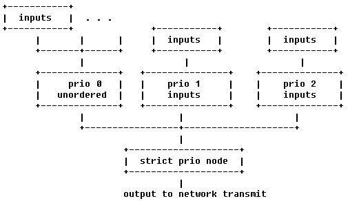
The actual qos tree configuration can be found at arch/arm/boot/dts/keystone-qostree.dtsi.
The device tree has attributes for configuring the QoS shaper. In the sections below we explain the various qos specific attributes which can be used to setup and configure a QoS shaper.
In the device tree we are setting up a shaper that is depicted below
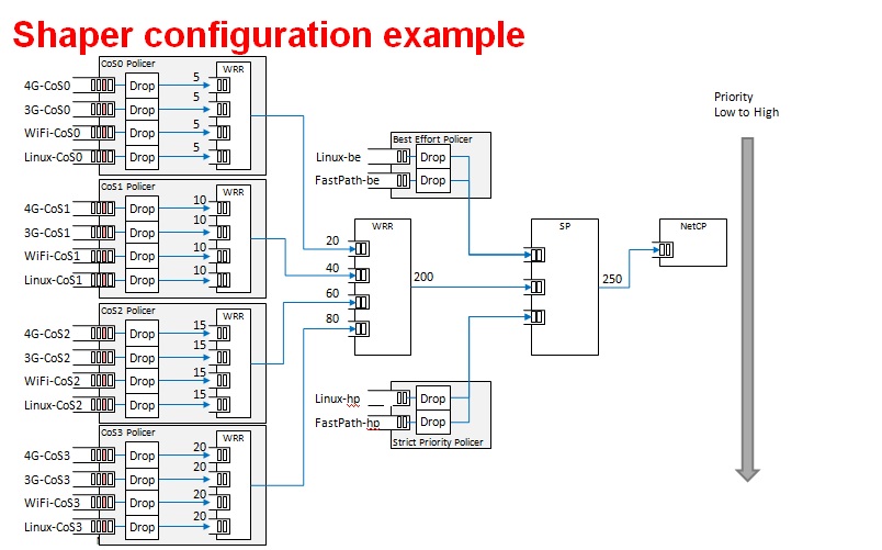
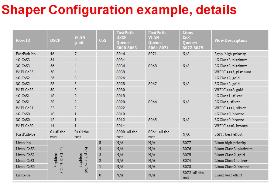
QoS Node Attributes
The following attributes are recognized within QoS configuration nodes:
- “strict-priority” and “weighted-round-robin”
e.g. strict-priority;
This attribute specifies the type of scheduling performed at a node. It is an error to specify both of these attributes in a particular node. The absence of both of these attributes defaults the node type to unordered(first come first serve).
- “weight”
e.g. weight = <80>;
This attribute specifies the weight attached to the child node of a weighted-round-robin node. It is an error to specify this attribute on a node whose parent is not a weighted-round-robin node.
- “priority”
e.g. priority = <1>;
This attribute specifies the priority attached to the child node of a strict-priority node. It is an error to specify this attribute on a node whose parent is not a strict-priority node. It is also an error for child nodes of a strict-priority node to have the same priority specified.
- “byte-units” or “packet-units”
e.g. byte-units;
The presence of this attribute indicates that the scheduler accounts for traffic in byte or packet units. If this attribute is not specified for a given node, the accounting mode is inherited from its parent node. If this attribute is not specified for the root node, the accounting mode defaults to byte units.
- “output-rate”
e.g. output-rate = <31250000 25000>;
The first element of this attribute specifies the output shaped rate in bytes/second or packets/second (depending on the accounting mode for the node). If this attribute is absent, it defaults to infinity (i.e., no shaping). The second element of this attribute specifies the maximum accumulated credits in bytes or packets (depending on the accounting mode for the node). If this attribute is absent, it defaults to infinity (i.e., accumulate as many credits as possible).
- “overhead-bytes”
e.g. overhead-bytes = <24>;
This attribute specifies a per-packet overhead (in bytes) applied in the byte accounting mode. This can be used to account for framing overhead on the wire. This attribute is inherited from parent nodes if absent. If not defined for the root node, a default value of 24 will be used. This attribute is passed through by inheritence (but ignored) on packet accounted nodes.
- “output-queue”
e.g. output-queue = <645>;
This specifies the QMSS queue on which output packets are pushed. This attribute must be defined only for the root node in the qos tree. Child nodes in the tree will ignore this attribute if specified.
- “input-queues”
e.g. input-queues = <8010 8065>;
This specifies a set of ingress queues that feed into a QoS node. This attribute must be defined only for leaf nodes in the QoS tree. Specifying input queues on non-leaf nodes is treated as an error. The absence of input queues on a leaf node is also treated as an error.
- “stats-class”
e.g. stats-class = “linux-best-effort”;
The stats-class attribute ties one or more input stage nodes to a set of traffic statistics (forwarded/discarded bytes, etc.). The system has a limited set of statistics blocks (up to 48), and an attempt to exceed this count is an error. This attribute is legal only for leaf nodes, and a stats-class attribute on an intermediate node will be treated as an error.
- “drop-policy”
e.g. drop-policy = “no-drop”
The drop-policy attribute specifies a drop policy to apply to a QoS node (tail drop, random early drop, no drop, etc.) when the traffic pattern exceeds specifies parameters. The drop-policy parameters are configured separately within device tree (see “Traffic Police Policy Attributes section below). This attribute defaults to “no drop” for applicable input stage nodes. If a node in the QoS tree specifies a drop-policy, it is an error if any of its descendent nodes (children, children of children, ...) are of weighted-round-robin or strict-priority types.
Traffic Police Policy Attributes
The following attributes are recognized within traffic drop policy nodes:
- “byte-units” or “packet-units”
e.g. byte-units;
The presence of this attribute indicates that the dropr accounts for traffic in byte or packet units. If this attribute is not specified, it defaults to byte units. Policies that use random early drop must be of byte unit type.
- “limit”
e.g. limit = <10000>;
Instantaneous queue depth limit (in bytes or packets) at which tail drop takes effect. This may be specified in combination with random early drop, which operates on average queue depth (instead of instantaneous). The absence of this attribute, or a zero value for this attribute disables tail drop behavior.
- “random-early-drop”
e.g. random-early-drop = <32768 65536 2 2000>;
The random-early-drop attribute specifies the following four parameters in order:
low threshold: No packets are dropped when the average queue depth is below this threshold (in bytes). This parameter must be specified.
high threshold: All packets are dropped when the average queue depth above this threshold (in bytes). This parameter is optional, and defaults to twice the low threshold.
max drop probability: the maximum drop probability
half-life: Specified in milli seconds. This is used to calculate the average queue depth. This parameter is optional and defaults to 2000.
Sysfs support
The keystone hardware queue driver has sysfs support for statistics, drop policies and the tree configuration.
root@k2hk-evm:~# cd /sys/devices/platform/soc/soc:qmss@2a40000/qos-inputs-0
root@k2hk-evm:/sys/devices/platform/soc/soc:qmss@2a40000/qos-inputs-0# ls
drop-policies qos-tree statistics
root@keystone-evm:/sys/devices/platform/soc/soc:qmss@2a40000/qos-inputs-0#
The above shows the location in the kernel where sysfs entries for the keystone hardware queue can be found. There are sysfs entries for the qos trees (qos-inuputs-0, qos-tree-inputs-1). Within the qos directory there are separate directories for statistics, drop-policies and the qos-tree itself. Each node in the tree is a separate directory entry, starting with the root (tip) entry.
- bytes forwarded
- bytes discarded
- packets forwarded
- packets discarded
cat /sys/devices/platform/soc/soc:qmss@2a40000/qos-inputs-0/statistics/linux-be/packets_forwarded
Drop policy configuration is also displayed for each drop policy. In the case of a drop policy, the parameters can also be changed. This is depicted below. Please note the the parameters that can be modified for tail drop are a subset of the parameters that can be modified for random early drop.
- directory entries to reach the subtrees feeding this node
- the input queues to this node (valid for leaf nodes only)
- the output queue from this node
- the output rate for the node. The current value can be shown by: “cat output_rate”. The value can be modified by: echo ”<val>” > output_rate
- the overhead bytes parameter for the node. The current value can be shown by: “cat overhead_bytes”. The value can be modified by: echo ”<val>” > overhead_bytes
- burst size . The current value can be shown by: “cat burst_size”. The value can be modified by: echo “<val>” > burst_size
- drop_policy . This is the name of the drop policy to be used.
- stats_class associated with node. This is the name of stats class to be used
- the priority of the node (for strict priority nodes only). The current value can be shown by: “cat priority”. The value can be modified by: echo “<val>” > priority
- weight : for wrr nodes. The current value can be shown by: “cat weight”. The value can be modified by: echo “<val>” > weight
Debug Filesystem support
Debug Filesystem(debugfs) support is also being provided for QoS support. To make use of debugfs support a user might have to mount a debugfs filesystem. This can be done by issuing the command (if /debug does not exist on your filesystem, you may need to create the directory first).
mount -t debugfs debugfs /debug
root@keystone-evm:/debug/qos-3# ls
config_profiles out_profiles queue_configs sched_ports
With the debugfs support we will be able to see the actual configuration of
- QoS scheduler ports
- Drop scheduler queue configs
- Drop scheduler output profiles
- Drop scheduler config profiles
root@k2hk-evm:/debug/qos-3# cat sched_ports
port 14
unit flags 15 group # 1 out q 8171 overhead bytes 24 throttle thresh 2501 cir credit 5120000 cir max 51200000
total q's 4 sp q's 0 wrr q's 4
queue 0 cong thresh 0 wrr credit 384000
queue 1 cong thresh 0 wrr credit 384000
queue 2 cong thresh 0 wrr credit 384000
queue 3 cong thresh 0 wrr credit 384000
port 15
unit flags 15 group # 1 out q 8170 overhead bytes 24 throttle thresh 2501 cir credit 5120000 cir max 51200000
total q's 4 sp q's 0 wrr q's 4
queue 0 cong thresh 0 wrr credit 384000
queue 1 cong thresh 0 wrr credit 384000
queue 2 cong thresh 0 wrr credit 384000
queue 3 cong thresh 0 wrr credit 384000
port 16
unit flags 15 group # 1 out q 8169 overhead bytes 24 throttle thresh 2501 cir credit 5120000 cir max 51200000
total q's 4 sp q's 0 wrr q's 4
queue 0 cong thresh 0 wrr credit 384000
queue 1 cong thresh 0 wrr credit 384000
queue 2 cong thresh 0 wrr credit 384000
queue 3 cong thresh 0 wrr credit 384000
port 17
unit flags 15 group # 1 out q 8168 overhead bytes 24 throttle thresh 2501 cir credit 5120000 cir max 51200000
total q's 4 sp q's 0 wrr q's 4
queue 0 cong thresh 0 wrr credit 384000
queue 1 cong thresh 0 wrr credit 384000
queue 2 cong thresh 0 wrr credit 384000
queue 3 cong thresh 0 wrr credit 384000
port 18
unit flags 15 group # 1 out q 8173 overhead bytes 24 throttle thresh 3126 cir credit 5120000 cir max 51200000
total q's 4 sp q's 0 wrr q's 4
queue 0 cong thresh 0 wrr credit 384000
queue 1 cong thresh 0 wrr credit 768000
queue 2 cong thresh 0 wrr credit 1152000
queue 3 cong thresh 0 wrr credit 1536000
port 19
unit flags 7 group # 1 out q 645 overhead bytes 24 throttle thresh 0 cir credit 6400000 cir max 51200000
total q's 3 sp q's 3 wrr q's 0
queue 0 cong thresh 0 wrr credit 0
queue 1 cong thresh 0 wrr credit 0
queue 2 cong thresh 0 wrr credit 0
root@k2hk-evm:/debug/qos-3#
Configuring QoS on an 1-GigE interface
To configure QoS on an interface, several definitions must be added to the device tree:
- Drop policies and a QoS tree must be defined. The outer-most QoS block must specify an output queue number; this may be the 1-GigE NETCP’s PA PDSP 5 (645) or CPSW (648), one of the 10-GigE CPSW’s queues (8752, 8753), or other queue as appropriate.
Example (keystone-qostree.dtsi):
droppolicies: default-drop-policies {
no-drop {
default;
packet-units;
limit = <0>;
};
...
all-drop {
byte-units;
limit = <0>;
};
};
Example (keystone-qostree.dtsi):
qostree0: qos-tree-0 {
strict-priority; /* or weighted-round-robin */
byte-units; /* packet-units or byte-units */
output-rate = <31250000 25000>;
overhead-bytes = <24>; /* valid only if units are bytes */
output-queue = <645>; /* allowed only on root node */
high-priority {
...
}
...
best-effort {
...
};
};
qostree1: qos-tree-1 {
strict-priority; /* or weighted-round-robin */
byte-units; /* packet-units or byte-units */
output-rate = <31250000 25000>;
overhead-bytes = <24>; /* valid only if units are bytes */
output-queue = <648>; /* allowed only on root node */
high-priority {
...
}
...
best-effort {
...
};
};
- QoS inputs must be defined to the hwqueue subsystem. The QoS inputs block defines which group of hwqueues will be used, and links to the set of drop policies and QoS tree to be used.
Example (k2hk-netcp.dtsi):
qmss: qmss@2a40000 {
...
queue-pools {
...
qos {
qosinputs0: qos-inputs-0 {
qrange = <8000 192>;
pdsp-id = <3>;
...
drop-policies = <&droppolicies>;
qos-tree = <&qostree0>;
reserved;
};
qosinputs1: qos-inputs-1 {
values = <6400 192>;
pdsp-id = <7>;
...
drop-policies = <&droppolicies>;
qos-tree = <&qostree2>;
reserved;
};
};
}
};
- A PDSP must be defined, and loaded with the QoS firmware.
Example (k2hk-netcp.dtsi):
qmss: qmss@2a40000 {
...
pdsps {
...
pdsp3@0x2a13000 {
firmware = "qos";
...
id = <3>;
};
pdsp7@0x2a17000 {
firmware = "qos";
...
id = <7>;
};
};
}; /* qmss */
- A NETCP QoS block must be defined. For each interface, an “interface-x” block is defined, which contains definitions for each of the QoS input subqueues to be associated with that interface.
Example (k2hk-netcp.dtsi):
netcp: netcp@2090000 {
...
qos@0 {
label = "netcp-qos";
...
interfaces {
qos0: interface-0 {
tx-queues = <645 8072 8073 8074
8075 8076 8077>;
};
qos1: interface-1 {
tx-queues = <645 6472 6473 6474
6475 6476 6477>;
};
};
};
- By default, Linux network traffic will be queued to the interface’s first subqueue. To classify and route packets from Linux to specific QoS queues, the Linux traffic control utility “tc” must be used. First a class-full root queuing discipline must be established for the interface, and then filters may be used to classify packets. These filters can use the “skbedit queue_mapping” action to set the subqueue number for the packet. Here is an example:
# Clear any existing configuration
tc qdisc del dev eth0 root
# Add DSMARK as the root qdisc
tc qdisc add dev eth0 root handle 1 dsmark indices 8 default_index 0
# Create filters to classify packets and route to queues
tc filter add dev eth0 parent 1:0 protocol ip prio 1 \
u32 match ip dport 5002 0xffff \
action skbedit queue_mapping 1
tc filter add dev eth0 parent 1:0 protocol ip prio 1 \
u32 match ip dport 5003 0xffff \
action skbedit queue_mapping 2
tc filter add dev eth0 parent 1:0 protocol ip prio 1 \
u32 match ip dport 5004 0xffff \
action skbedit queue_mapping 3
tc filter add dev eth0 parent 1:0 protocol ip prio 1 \
u32 match ip dport 5005 0xffff \
action skbedit queue_mapping 4
tc filter add dev eth0 parent 1:0 protocol ip prio 1 \
u32 match ip dport 5006 0xffff \
action skbedit queue_mapping 5
Please refer to the Linux Advanced Routing & Traffic Control how-tos and related manpages available on the Internet for more information on “tc”.
Disabling QoS on an 1-GigE interface
The released “keystone-qostree.dtsi” file contains definitions for two QoS trees which are associated with the first two ports on the 1-GigE interface in the “k2hk-netcp.dtsi” file. These default trees are configured so that traffic queued to interface subqueue 0 will bypass the QoS tree. Only traffic specifically directed to subqueues 1-6 will be processed through the hardware QoS subsystem. This may be sufficient for your needs. However, you may prefer to remove the QoS configuration entirely from the device tree.
To disable QoS on the two 1-GigE interfaces
- delete all the qos related blocks or entries shown in the examples in section Configuring QoS on an 1-GigE interface, namely
- droppolicies: default-drop-policies {...}
- qostree0: qos-tree-0 {...}
- qostree1: qos-tree-1 {...}
- qos-inputs-0 {...}
- qos-inputs-1 {...}
- pdsp3@0x2a13000 {...}
- pdsp7@0x2a17000 {...}
- qos@0 {...}
Configuring QoS on a 10-GigE interface
The following snippets together shows how to remove the QoS tree associated with the second port of the 1-GigE interface and associate it with the first port on the 10-GigE interface. In these snippets, we only depict and highlight the modifications made to the above 1-GigE examples. Contents not shown in the definitions should just be copy and paste from the file k2hk-netcp.dtsi.
Note: this is only for demonstration purpose and is not part of the release.
- Remove “netcp-qos = <&qos1>” from 1-GigE’s netcp@2090000 > netcp-interfaces > interface-1 {...}.
- Remove qos1: interface-1 { ... } from 1-GigE’s netcp qos block.
netcp: netcp@2090000 {
...
qos@0 {
label = "netcp-qos";
...
interfaces {
qos0: interface-0 {
tx-queues = <645 8072 8073 8074
8075 8076 8077>;
};
/* qos1:interface-1 removed */
};
};
- Modify the output-queue number of qostree1 to that of the transmit queue of the 10-GigE’s first port.
qostree1: qos-tree-1 {
output-queue = <8752>; /* allowed only on root node */
};
- Define a qos block in 10-GigE’s netcp@2f00000 > netcp-devices {...}.
netcpx: netcp@2f00000 {
...
netcp-devices {
...
qos@0 {
label = "netcpx-qos";
compatible = "ti,netcp-qos";
tx-channel = "xnettx";
interfaces {
qos1: interface-1 {
tx-queues = <645 6472 6473 6474
6475 6476 6477>;
};
};
};
};
};
- Finally, add a qos interface to 10-GigE’s interface-1:
netcpx: netcp@2f00000 {
...
netcp-interfaces {
...
interface-1 {
...
netcp-xqos = <&qos1>;
};
};
};
Using Accumulated queues for Network interfaces
Accumulated queues allows interrupt pacing for rx queue interrupts. Accumulated queue range is defined in DTS under the queue-pools. See keystone-<SoC>-netcp.dtsi
accumulator {
acc-low-0 {
qrange = <480 32>;
accumulator = <0 47 16 2 50>;
interrupts = <0 226 0xf01>;
multi-queue;
qalloc-by-id;
};
};
netcp: netcp@2000000 {
// other bindings
netcp-interfaces {
interface-0 {
rx-channel = "netrx0";
rx-pool = <1024 12>;
tx-pool = <1024 12>;
rx-queue-depth = <128 128 0 0>;
rx-buffer-size = <1518 4096 0 0>;
rx-queue = <8704>; <============================= replace this with 480
tx-completion-queue = <8706>;
efuse-mac = <1>;
netcp-gbe = <&gbe0>;
netcp-pa = <&pa0>;
};
interface-1 {
rx-channel = "netrx1";
rx-pool = <1024 12>;
tx-pool = <1024 12>;
rx-queue-depth = <128 128 0 0>;
rx-buffer-size = <1518 4096 0 0>;
rx-queue = <8705>;<============================= replace this with 481
tx-completion-queue = <8707>;
efuse-mac = <0>;
local-mac-address = [02 18 31 7e 3e 6f];
netcp-gbe = <&gbe1>;
netcp-pa = <&pa1>;
};
};
};
If PA is used, make sure rx-route which specifiy start queue is also replaced as shown below.
netcp: netcp@2000000 {
// other bindings
netcp-devices {
// other bindings
pa@0 {
// other bindings
rx-route = <8704 22>; <=============================== change this to <480 22>
// other bindings
};
};
};
K2HK EVM Gigabit MDC/MDIO Signal Integrity Issue
Due to a MDC/MDIO signal integrity issue in the EVM that gets showed up when a RTM Breakout Card is connected to a K2HK EVM, the Gigabit Ethernet link can go down/up repeatedly with no apparent reason except with some debug prints similar to the following shown:
[ 21.445070] netcp-1.0 2620110.netcp eth0: Link is Down
[ 22.175392] netcp-1.0 2620110.netcp eth0: Link is Up - 1Gbps/Full - flow control off
[ 24.065092] netcp-1.0 2620110.netcp eth1: Link is Down
[ 34.175092] netcp-1.0 2620110.netcp eth0: Link is Down
Software Workaround
A workaround that helps to avoid the issue is to disable the Gigabit MDIO and modify the Gigabit Ethernet interface link type to SGMII_LINK_MAC_PHY_NO_MDIO (4) by making the following changes in the default K2HK devicetree bindings.
diff --git a/arch/arm/boot/dts/keystone-k2hk-evm.dts b/arch/arm/boot/dts/keystone-k2hk-evm.dts
index ff1c0fc..0cfa003 100644
--- a/arch/arm/boot/dts/keystone-k2hk-evm.dts
+++ b/arch/arm/boot/dts/keystone-k2hk-evm.dts
@@ -200,6 +200,7 @@
};
};
+/*
&mdio {
status = "ok";
thphy0: ethernet-phy@0 {
@@ -212,6 +213,7 @@
reg = <1>;
};
};
+*/
&gbe_serdes {
status = "okay";
diff --git a/arch/arm/boot/dts/keystone-k2hk-netcp.dtsi b/arch/arm/boot/dts/keystone-k2hk-netcp.dtsi
index f51d20b..0d98f1f 100644
--- a/arch/arm/boot/dts/keystone-k2hk-netcp.dtsi
+++ b/arch/arm/boot/dts/keystone-k2hk-netcp.dtsi
@@ -370,14 +370,14 @@ netcp: netcp@2000000 {
gbe0: interface-0 {
phys = <&serdes_lane0>;
slave-port = <0>;
- link-interface = <1>;
- phy-handle = <ðphy0>;
+ link-interface = <4>;
+ /* phy-handle = <ðphy0>; */
};
gbe1: interface-1 {
phys = <&serdes_lane1>;
slave-port = <1>;
- link-interface = <1>;
- phy-handle = <ðphy1>;
+ link-interface = <4>;
+ /* phy-handle = <ðphy1>; */
};
};
Hardware Fix
As of Oct 10, 2016, it is reported that Mistral Solutions Inc. (vendor of the RTM-BOC) has produced a newer version (v2.16) of the RTM-BOC that has fixed the signal integrity issue. However the hardware fix has not yet been verified by the software development team.
10G SerDes Auto-Configuration
The 10G ethernet switch found in K2HK and K2E includes a MCU which allows running a firmware to perform SerDes configuration without the intervention of the switch driver.
Enabling Auto-Configuration
To enable 10G SerDes auto-configuration, add the following in keystone-k2hk-evm.dts or keystone-k2e-evm.dts.
+&xgbe_subsys {
+ status = "okay";
+};
+
+&xgbe_pcsr {
+ status = "okay";
+};
+
+&xgbe_serdes {
+ status = "okay";
+
+ clocks = <&clkxge>;
+ clock-names = "xge_clk";
+
+ mcu-firmware {
+ status = "okay";
+
+ lane@0 {
+ status = "okay";
+ };
+
+ lane@1 {
+ status = "okay";
+ };
+ };
+};
+
+&netcpx {
+ status = "okay";
+};
Usage Note
- After the DUT bootup is completed, notice the all the enabled 10G interfaces are up and running. Then verify the 10G interfaces as usual, such as using the ping command.
- Due to constraints there are several usage notes concerning the firmware:
- When autonegotiation occurs there is a reset asserted on the lane
that affects the MAC layer and switch.
- During a simultaneous boot of two devices they will sync and autonegotiate before the aforementioned layers are configured. There is no issue in this scenario.
- If a single device is reset this will cause autonegotiation to occur again. This will reset the lane of the device that stayed persistently on. When this happens, re-program the MAC_CONTROL register for that lane, otherwise, an interface toggle using ‘ifconfig’ is sufficient to reconfigure the interface back to a working state.
- When switching between a non-FW configuration and a FW configuration a POR is required.
- Due to errata KeyStoneII.BTS_errata_advisory.29:10GbE PCS Causes
Data Corruption, occasionally on link negotiation there may be high
levels of packet loss.
- The symptoms of this are high packet loss, CRC and alignment errors, and 0xff block errors in a small time period.
- When this case is detected, assert SerDes Signal Detect low to
reforce an autonegotiation, then follow the above procedure for an
interface toggle.
- Signal detect is located at register LANE_004, BITS[2:1]. BIT[2] is override enable and BIT[1] is the override value. Once override enable is set it will force the override value as the value of signal detect. To force signal detect low, the proper write would be BITS[2:1] = 0x2. Once this has been set the firmware will respond to the lane being down and re-do auto-negotiation, automatically clearing the signal detect low state.
- If there is a total loss of signal, restarting the firmware may help.
- The firmware can be restarted by writing to CPU_CTRL register, POR_EN bit 29. Set this bit high, then set it low with at least 10ms in between.
3.3.4.15. PRUSS
Introduction
All the Industrial Development Kit (IDK) boards can support 2 Ethernet ports per PRUSS (Programmable Real-time Unit Subsystem). Although it is meant to support real-time Industrial Ethernet protocols this wiki page will only describe how to get standard Ethernet working using the Kernel’s PRU Ethernet driver.
Acronyms & definitions
| Acronym | Definition |
|---|---|
| IDK | Industrial Development Kit |
| PRU | Programmable Real-time Unit |
Table: PRU Ethernet Driver: Acronyms
PRU Ethernet Driver Architecture
Below figure shows the PRU Ethernet Driver architecture.
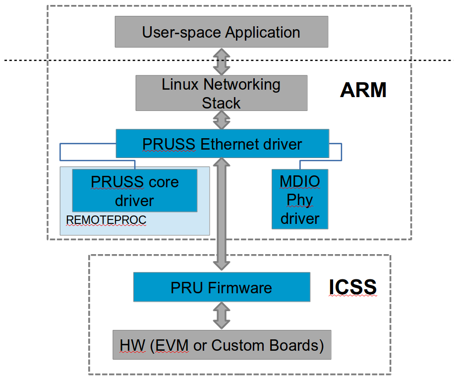
Overview
Each PRUSS instance contains 2 PRU cores and 2 Ethernet PHY interfaces. This means that each PRU core can fully own one Ethernet port allowing us to create a dual Ethernet solution. The firmware running on each PRU implements the Ethernet MAC application. It uses the System OCMC RAM to exchange network packets between firmware and PRU Ethernet kernel driver.
Before the PRU Ethernet kernel driver can start transferring packets, the following things have to be done:
- Initialize the PRU cores and load the correct formware. This is taken care by the Remoteproc core via the PRU Remoteproc driver (pru_rproc.c).
- Initialize the PRUSS Interrupt Controller (INTC) and configure the interrupt mapping as per firmware requirement. This is done by the PRUSS INTC driver (pruss_intc.c).
- Initialize the Ethernet PHYs over the MDIO interface. This is done by the PHY MDIO driver (davinci_mdio.c).
Once all initialization is done the PRU Ethernet driver (prueth.c) takes over and interfaces with the firmware using PRUSS internal RAM (DRAM & SRAM) and the System OCMC RAM. It also interfaces to the Linux Networking stack to provide the standard networking interface to user space.
Files
| S.No | Location | Description |
|---|---|---|
| 1 | drivers/net/ethernet/ti/prueth.c | PRU Ethernet driver |
| 2 | drivers/remoteproc/pruss.c | PRUSS core driver |
| 3 | drivers/remoteproc/pruss_intc.c | PRUSS INTC driver |
| 4 | drivers/remoteproc/pru_rproc.c | PRU Remoteproc driver |
| 5 | drivers/net/ethernet/ti/davinci_mdio.c | PHY MDIO driver |
| 6 | lib/firmware/ti-pruss/ | Firmware |
Board specific Setup Details
AM335x-ICE-v2
This board has only 2 Ethernet ports that can be used either as CPSW Ethernet or PRUSS Ethernet. For PRUSS Ethernet configration place jumpers J18 and J19 at MII position before powering up the board.
AM437x-IDK
This board as one Gigabit (CPSW) Ethernert port and 2 PRUSS Ethernet ports. No special board configuration is needed to use all ports.
K2G-ICE EVM
This board has one Gigabit (netCP) Ethernet port and 4 PRUSS Ethernet ports. No special board configuration is needed to use all ports.
AM571x-IDK
This board has 2 Gigabit (CPSW) Ethernet ports and 4 PRUSS Ethernet ports. Due to pinmux limitations it can support either of the following configurations
- Jumper J51 placed. LCD + 2 Gigabit (CPSW) + 2 PRUSS Ethernet ports (PRU2_ETH0 and PRU2_ETH1)
OR
- Jumper J51 removed. No LCD, 2 Gigabit (CPSW) + 4 PRUSS Ethernet ports.
NOTE: Jumper must be configured before powering up the board.
AM572x-IDK
This board has 2 Gigabit (CPSW) Ethernet ports and 4 PRUSS Ethernet ports. However, only 2 Gigabit + 2 PRUSS Ethernet ports (PRU2_ETH0 and PRU2_ETH1) are supported due to pinmux limitations.
NOTE: Only ES2.0 silicon (Board Rev1.3 or later) is supported as older Silicon uses a older version of PRUSS core that is not compatible with the supplied firmware.
Kernel configuration
To enable/disable PRU Ethernet driver support, start the Linux Kernel Configuration tool:
$ make menuconfig ARCH=arm
Make sure Remoteproc and PRUSS core driver is enabled.
Select Device drivers from the main menu.
...
[*] Networking support --->
Device Drivers -->
File systems --->
...
Select Remoteproc drivers.
...
[*] IOMMU Hardware Support --->
Remoteproc drivers --->
Rpmsg drivers --->
...
Enable the below drivers.
...
<M> Support for Remote Processor subsystem
<M> TI PRUSS remoteproc support
<M> Keystone Remoteproc support
...
Go back to the Device drivers menu Network device support.
...
IEEE 1394 (FireWire) support --->
[*] Network device support --->
[ ] Open-Channel SSD target support ----
...
Select Ethernet driver support.
...
Distributed Switch Architecture drivers ----
[*] Ethernet driver support --->
< > FDDI driver support
...
Select TI PRU Ethernet driver.
...
< > TI ThunderLAN support
<M> TI PRU Ethernet EMAC/Switch driver
[ ] VIA devices
...
Driver Usage & Testing
You can use standard Linux networking tools to test the networking interface (e.g. ifconfig, ping, iperf, scp, ethtool, etc)
3.3.4.16. PCIe End Point
Introduction
PCI controller IPs integrated in DRA7x/AM57x and 66AK2G SoCs are capable of operating either in Root Complex mode (host) or Endpoint mode (device). When operating in endpoint mode, the controller can be configured to be used as any function depending on the use case (‘Test endpoint’ is the only PCIe EP function supported in Linux kernel right now)
This wiki page provides usage information of PCIe EP Linux driver.
Setup Details
The following boards have standard female connector
| dra74x-evm |
| dra72x-evm |
| am571x-idk |
| am572x-idk |
| 66ak2g-gp-evm |
These boards are by default intended to be operated in Root Complex mode. So in order to connect two boards, a specialized cable like below is required.
This cable can be obtained from https://www.adexelec.com/pciexp.htm. Use either X1 cable or X4 cable depending on the slot provided in the board. The part number is PE-FLEX1-MM-CX-3” (for 3” cable length x1)
Modify the cable to remove resistors in CK+ and CK- in order to avoid ground loops (power) and smoking clock drivers (clk+/-).
The ends of the modified cable should look like below
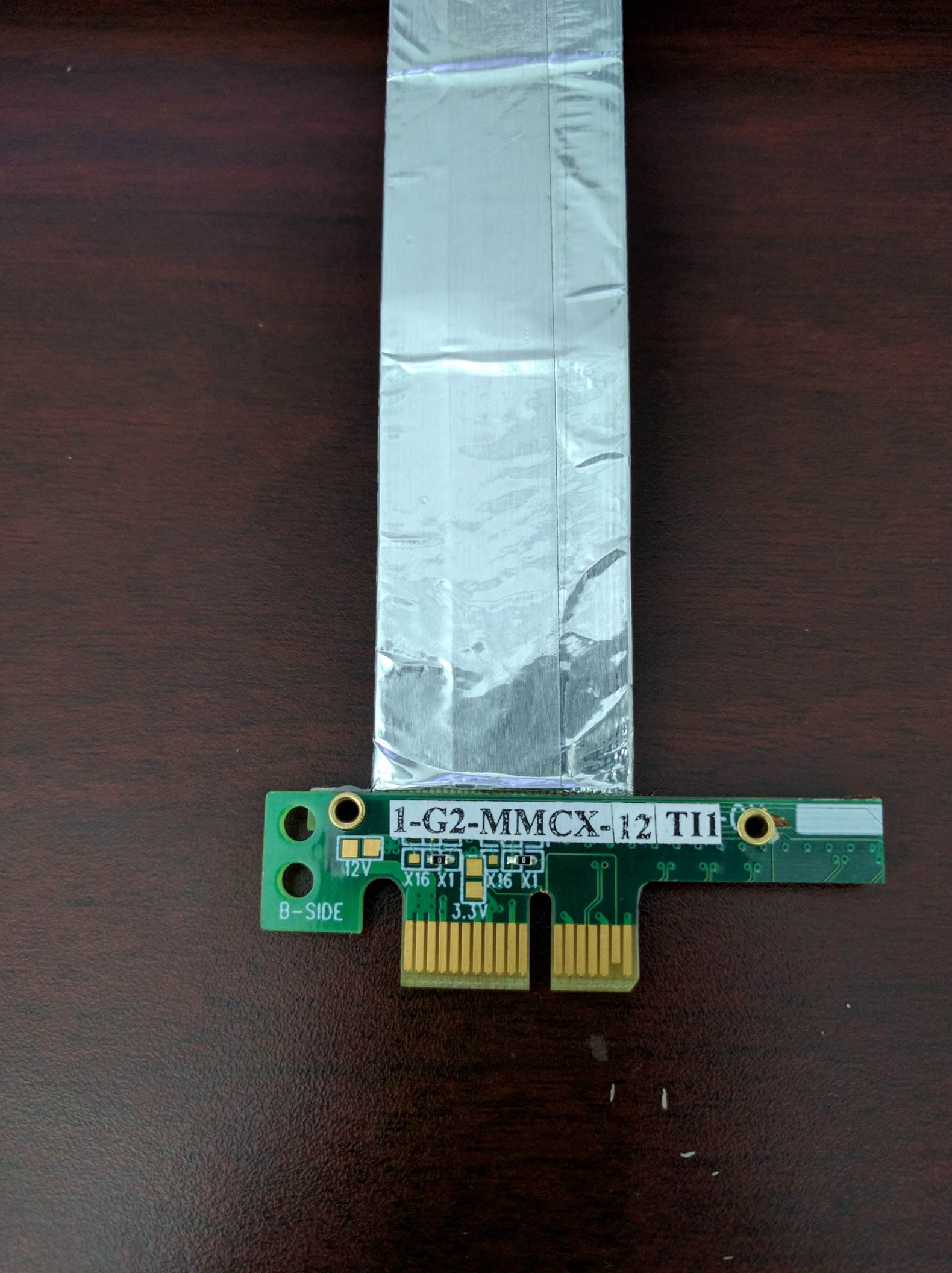
B side
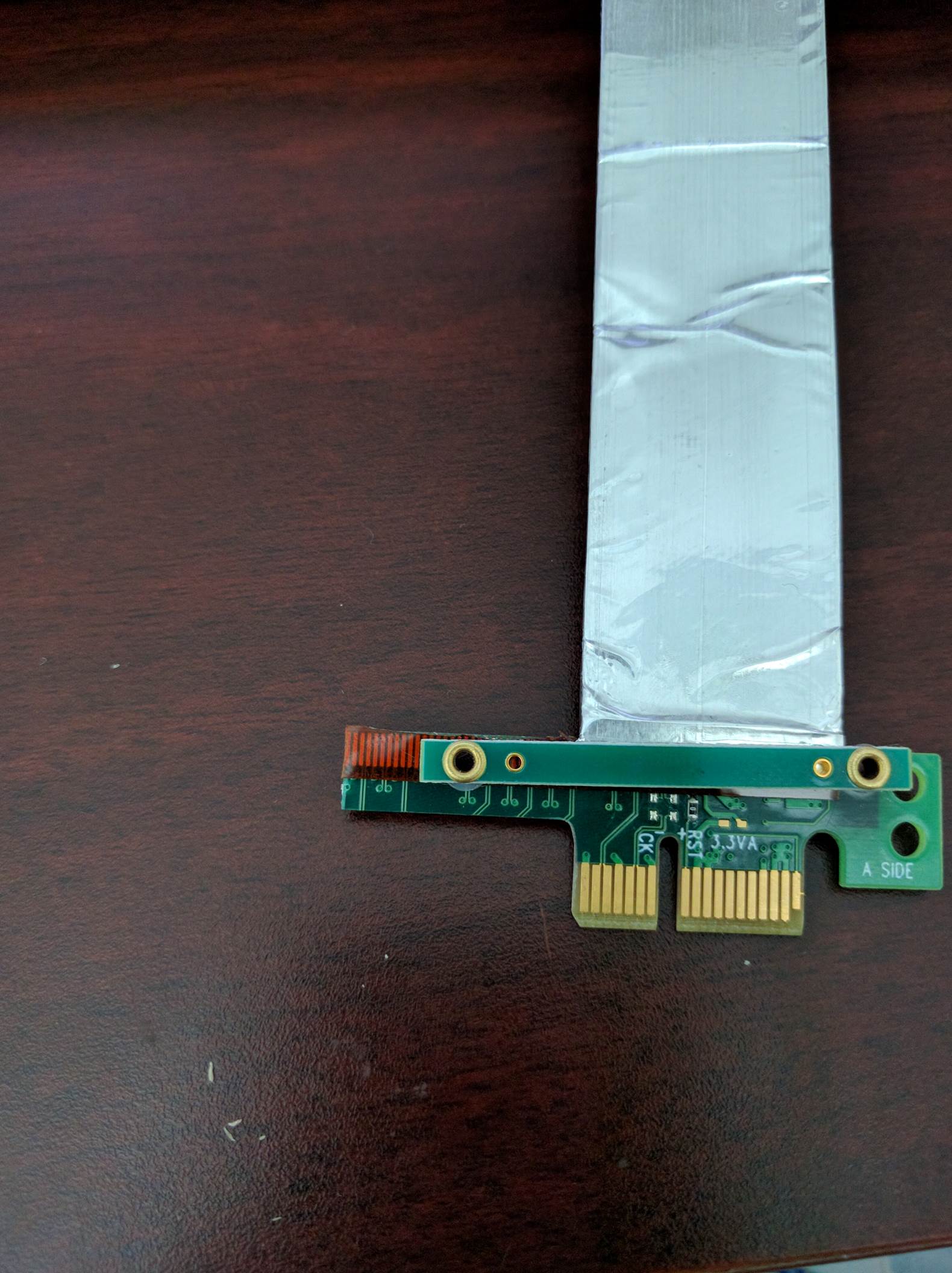
A side
A side side2
B side side2
Image of a dra72-evm and dra7-evm connected back to back. There is no restriction on which end of the cable should be connected to host and device.
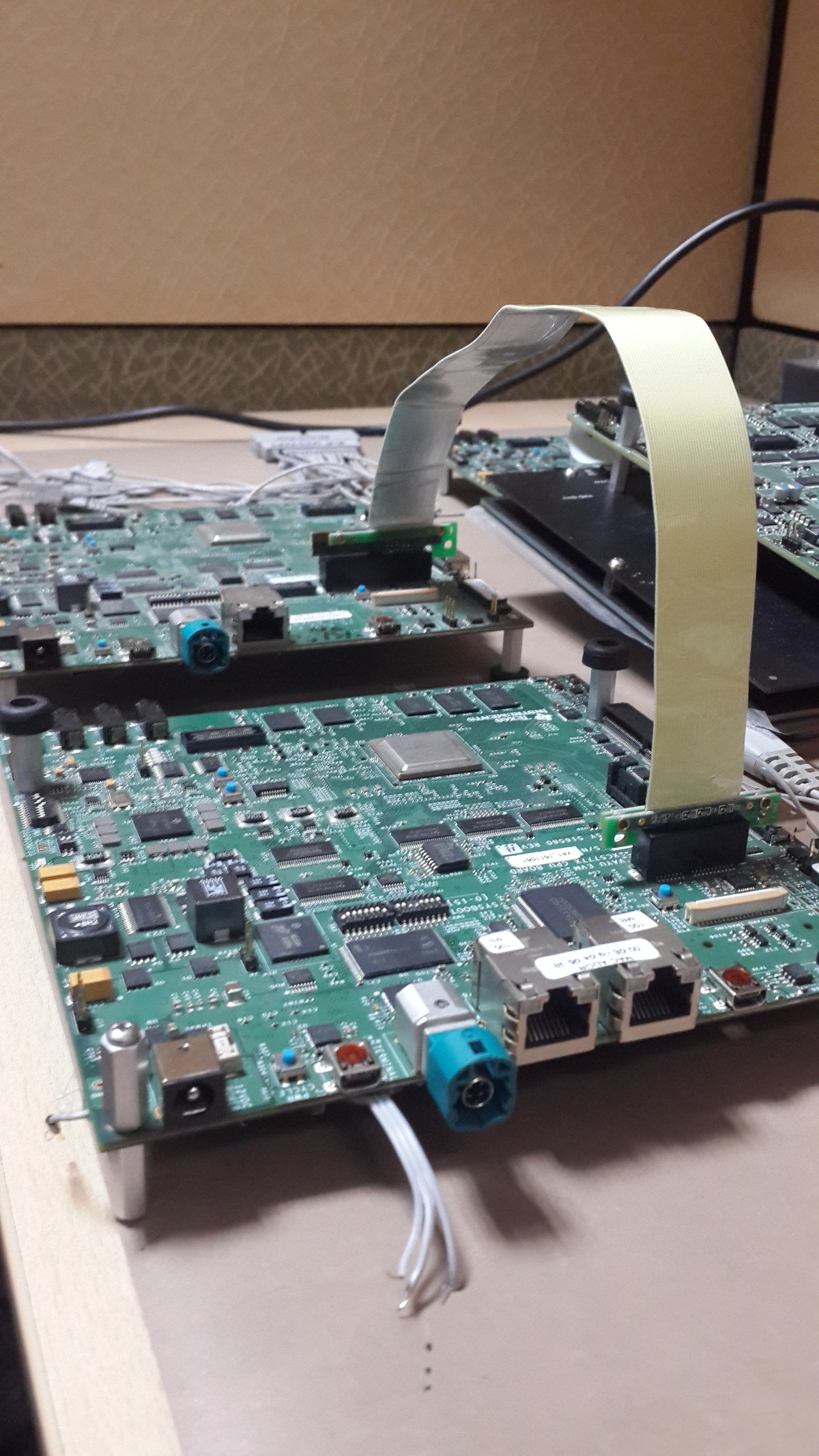
..note:
For AM572x GP EVM, there is a Mini PCIe connector on
the LCD board. To connect 2 boards involving a AM572x GP EVM, a
mPCIe-to-PCIe adapter is needed.
EP Device
DTS Modification
The default dts is configured to be used in root complex mode. In order to use it in endpoint mode, the following changes has to be made in dts file.
To configure dra7-evm in EP mode:
diff --git a/arch/arm/boot/dts/dra7-evm.dts b/arch/arm/boot/dts/dra7-evm.dts
index eedd930..93d9f17 100644
--- a/arch/arm/boot/dts/dra7-evm.dts
+++ b/arch/arm/boot/dts/dra7-evm.dts
@@ -1084,7 +1084,7 @@
vdd-supply = <&smps7_reg>;
};
-&pcie1_rc {
+&pcie1_ep {
status = "okay";
};
To configure dra72-evm in EP mode:
diff --git a/arch/arm/boot/dts/dra72-evm-common.dtsi b/arch/arm/boot/dts/dra72-evm-common.dtsi
index f914e6a..9697ea3 100644
--- a/arch/arm/boot/dts/dra72-evm-common.dtsi
+++ b/arch/arm/boot/dts/dra72-evm-common.dtsi
@@ -708,6 +708,6 @@
watchdog-timers = <&timer10>;
};
-&pcie1_rc {
+&pcie1_ep {
status = "okay";
};
To configure am572x-idk in EP mode:
diff --git a/arch/arm/boot/dts/am572x-idk.dts b/arch/arm/boot/dts/am572x-idk.dts
index b2edeab..1ef70b3 100644
--- a/arch/arm/boot/dts/am572x-idk.dts
+++ b/arch/arm/boot/dts/am572x-idk.dts
@@ -428,11 +428,11 @@
};
&pcie1_rc {
- status = "okay";
gpios = <&gpio3 23 GPIO_ACTIVE_HIGH>;
};
&pcie1_ep {
+ status = "okay";
gpios = <&gpio3 23 GPIO_ACTIVE_HIGH>;
};
Linux Driver Configuration
The following config options has to be enabled in order to configure the PCI controller to be used as a “Endpoint Test” function driver.
CONFIG_PCI_ENDPOINT=y
CONFIG_PCI_EPF_TEST=y
CONFIG_PCI_DRA7XX_EP=y
Endpoint Controller devices and Function drivers
To find the list of endpoint controller devices in the system:
# ls /sys/class/pci_epc/
51000000.pcie_ep
To find the list of endpoint function drivers in the system:
# ls /sys/bus/pci-epf/drivers
pci_epf_test
Using the pci-epf-test function driver
The pci-epf-test function driver can be used to test the endpoint functionality of the PCI controller. Some of the tests that’s currently supported are
- BAR tests
- Interrupt tests (legacy/MSI)
- Read tests
- Write tests
- Copy tests
4.4 Kernel
creating pci-epf-test device
PCI endpoint function device can be created using the configfs. To create pci-epf-test device, the following commands can be used
# mount -t configfs none /sys/kernel/config
# cd /sys/kernel/config/pci_ep/
# mkdir pci_epf_test.0
The “mkdir pci_epf_test.0” above creates the pci-epf-test function device. The name given to the directory preceding ‘.’ should match with the name of the driver listed in ‘/sys/bus/pci-epf/drivers’ in order for the device to be bound to the driver.
The PCI endpoint framework populates the directory with configurable fields.
# cd pci_epf_test.0
# ls
baseclass_code function revid vendorid
cache_line_size interrupt_pin subclass_code
deviceid peripheral subsys_id
epc progif_code subsys_vendor_id
The driver populates these entries with default values when the device is bound to the driver. The pci-epf-test driver populates vendorid with 0xffff and interrupt_pin with 0x0001
# cat vendorid
0xffff
# cat interrupt_pin
0x0001
configuring pci-epf-test device
The user can configure the pci-epf-test device using the configfs. In order to change the vendorid and the number of MSI interrupts used by the function device, the following command can be used.
# echo 0x104c > vendorid
# echo 16 > msi_interrupts
Binding pci-epf-test device to a EP controller
In order for the endpoint function device to be useful, it has to be bound to a PCI endpoint controller driver. Use the configfs to bind the function device to one of the controller driver present in the system.
# echo "51000000.pcie_ep" > epc
Once the above step is completed, the PCI endpoint is ready to establish a link with the host.
4.9 Kernel
creating pci-epf-test device
PCI endpoint function device can be created using the configfs. To create pci-epf-test device, the following commands can be used
# mount -t configfs none /sys/kernel/config
# cd /sys/kernel/config/pci_ep/
# mkdir dev
# mkdir dev/epf/pci_epf_test.0
The “mkdir dev/epf/pci_epf_test.0” above creates the pci-epf-test function device. The name given to the directory preceding ‘.’ should match with the name of the driver listed in ‘/sys/bus/pci-epf/drivers’ in order for the device to be bound to the driver.
The PCI endpoint framework populates the directory with configurable fields.
# ls dev/epf/pci_epf_test.0/
baseclass_code function revid vendorid
cache_line_size interrupt_pin subclass_code
deviceid peripheral subsys_id
epc progif_code subsys_vendor_id
The driver populates these entries with default values when the device is bound to the driver. The pci-epf-test driver populates vendorid with 0xffff and interrupt_pin with 0x0001
# cat dev/epf/pci_epf_test.0/vendorid
0xffff
# cat dev/epf/pci_epf_test.0/interrupt_pin
0x0001
configuring pci-epf-test device
The user can configure the pci-epf-test device using the configfs. In order to change the vendorid and the number of MSI interrupts used by the function device, the following command can be used.
Configure Texas Instruments as the vendor.
# echo 0x104c > dev/epf/pci_epf_test.0/vendorid
If the endpoint is a DRA74x or AM572x device:
# echo 0xb500 > dev/epf/pci_epf_test.0/deviceid
If the endpoint is a DRA72x or AM572x device:
# echo 0xb501 > dev/epf/pci_epf_test.0/deviceid
Then finally:
# echo 16 > dev/epf/pci_epf_test.0/msi_interrupts
Binding pci-epf-test device to a EP controller
In order for the endpoint function device to be useful, it has to be bound to a PCI endpoint controller driver. Use the configfs to bind the function device to one of the controller driver present in the system.
# echo "51000000.pcie_ep" > dev/epc
Once the above step is completed, the PCI endpoint is ready to establish a link with the host.
4.14
The following steps should be followed for the upstreamed solution (from 4.12 kernel). The custom solution used in 4.9/4.4 should not be used for upstreamed solution.
creating pci-epf-test device
PCI endpoint function device can be created using the configfs. To create pci-epf-test device, the following commands can be used
# mount -t configfs none /sys/kernel/config
# cd /sys/kernel/config/pci_ep/
# mkdir functions/pci_epf_test/func1
The “mkdir functions/pci_epf_test/func1” above creates the pci-epf-test function device.
The PCI endpoint framework populates the directory with configurable fields.
# ls functions/pci_epf_test/func1
baseclass_code function revid vendorid
cache_line_size interrupt_pin subclass_code
deviceid peripheral subsys_id
epc progif_code subsys_vendor_id
The driver populates these entries with default values when the device is bound to the driver. The pci-epf-test driver populates vendorid with 0xffff and interrupt_pin with 0x0001
# cat functions/pci_epf_test/func1/vendorid
0xffff
# cat functions/pci_epf_test/func1/interrupt_pin
0x0001
configuring pci-epf-test device
The user can configure the pci-epf-test device using the configfs. In order to change the vendorid and the number of MSI interrupts used by the function device, the following command can be used.
Configure Texas Instruments as the vendor.
# echo 0x104c > functions/pci_epf_test/func1/vendorid
If the endpoint is a DRA74x or AM572x device:
# echo 0xb500 > functions/pci_epf_test/func1/deviceid
If the endpoint is a DRA72x or AM572x device:
# echo 0xb501 > functions/pci_epf_test/func1/deviceid
Then finally:
# echo 16 > functions/pci_epf_test/func1/msi_interrupts
Binding pci-epf-test device to a EP controller
In order for the endpoint function device to be useful, it has to be bound to a PCI endpoint controller driver. Use the configfs to bind the function device to one of the controller driver present in the system.
# ln -s functions/pci_epf_test/func1 controllers/51000000.pcie_ep/
Starting the EP device
In order for the EP device to be ready to establish the link, the following command should be given
# echo 1 > controllers/51000000.pcie_ep/start
Once the above step is completed, the PCI endpoint is ready to establish a link with the host.
66AK2G Limitation
K2G outbound transfers has a limitation that the target address should be aligned to a minimum of 1MB address. This restriction is because of PCIE_OB_OFFSET_INDEXn where BITS 1 to 19 is reserved. (Please note 1MB is minimum alignment and it can be changed to 1MB/2MB/4MB/8MB by specifying it in PCIE_OB_SIZE register).
Outbound transfers are used by PCI endpoint to access RC’s memory and for raising MSI interrupts. So with 1MB restriction both RC memory and MSI interrupts will be impacted since standard linux API’s like dma_alloc_coherent, get_free_pages etc.. doesn’t give 1MB aligned memory. While custom driver can be created to get 1MB aligned memory for accessing RC’s memory, MSI memory is allocated by RC controller driver and there is no way to tell it to give 1MB aligned address.
These restrictions are not specified in PCI standard and is bound to cause issues for 66AK2G users.
HOST Device
The PCI EP device must be powered-on and configured before the PCI HOST device. This restriction is because the PCI HOST doesn’t have hot plug support.
Linux Driver Configuration
The following config options has to be enabled in order to use the “Endpoint Test” PCI device.
CONFIG_PCI=y
CONFIG_PCI_ENDPOINT_TEST=y
CONFIG_PCI_DRA7XX_HOST=y
lspci output
00:00.0 PCI bridge: Texas Instruments Device 8888 (rev 01)
01:00.0 Unassigned class [ff00]: Texas Instruments Device b500
Using the Endpoint Test function device
pci_endpoint_test driver creates the Endpoint Test function device (/dev/pci-endpoint-test.0) which will be used by the following pcitest utility. pci_endpoint_test can either be built-in to the kernel or built as a module. For testing legacy interrupt, MSI interrupt has to disabled in the host.
In order to not enable MSI (for testing legacy interrupt in DRA7)
insmod pci_endpoint_test.ko no_msi=1
Please note MSI interrupt by default is not enabled for K2G.
pcitest.sh added in tools/pci/ can be used to run all the default PCI endpoint tests. Before pcitest.sh can be used pcitest.c should be compiled using
cd <kernel-dir>
make headers_install ARCH=arm
arm-linux-gnueabihf-gcc -Iusr/include tools/pci/pcitest.c -o pcitest
cp pcitest <rootfs>/usr/sbin/
cp tools/pci/pcitest.sh <rootfs>
pcitest.sh output
root@dra7xx-evm:~# ./pcitest.sh
BAR tests
BAR0: OKAY
BAR1: OKAY
BAR2: OKAY
BAR3: OKAY
BAR4: NOT OKAY
BAR5: NOT OKAY
Interrupt tests
LEGACY IRQ: NOT OKAY
MSI1: OKAY
MSI2: OKAY
MSI3: OKAY
MSI4: OKAY
MSI5: OKAY
MSI6: OKAY
MSI7: OKAY
MSI8: OKAY
MSI9: OKAY
MSI10: OKAY
MSI11: OKAY
MSI12: OKAY
MSI13: OKAY
MSI14: OKAY
MSI15: OKAY
MSI16: OKAY
MSI17: NOT OKAY
MSI18: NOT OKAY
MSI19: NOT OKAY
MSI20: NOT OKAY
MSI21: NOT OKAY
MSI22: NOT OKAY
MSI23: NOT OKAY
MSI24: NOT OKAY
MSI25: NOT OKAY
MSI26: NOT OKAY
MSI27: NOT OKAY
MSI28: NOT OKAY
MSI29: NOT OKAY
MSI30: NOT OKAY
MSI31: NOT OKAY
MSI32: NOT OKAY
Read Tests
READ ( 1 bytes): OKAY
READ ( 1024 bytes): OKAY
READ ( 1025 bytes): OKAY
READ (1024000 bytes): OKAY
READ (1024001 bytes): OKAY
Write Tests
WRITE ( 1 bytes): OKAY
WRITE ( 1024 bytes): OKAY
WRITE ( 1025 bytes): OKAY
WRITE (1024000 bytes): OKAY
WRITE (1024001 bytes): OKAY
Copy Tests
COPY ( 1 bytes): OKAY
COPY ( 1024 bytes): OKAY
COPY ( 1025 bytes): OKAY
COPY (1024000 bytes): OKAY
COPY (1024001 bytes): OKAY
Files
S.No Location Description 1 drivers/pci/endpoint/pci-epc-core.c drivers/pci/endpoint/pci-ep-cfs.c
drivers/pci/endpoint/pci-epc-mem.c
drivers/pci/endpoint/pci-epf-core.c
PCI Endpoint Framework 2 drivers/pci/endpoint/functions/pci-epf-test.c PCI Endpoint Function Driver 3 drivers/misc/pci_endpoint_test.c PCI Driver 4 tools/pci/pcitest.c tools/pci/pcitest.sh
PCI Userspace Tools 5 *4.4 Kernel* drivers/pci/controller/pci-dra7xx.c
drivers/pci/controller/pcie-designware.c
drivers/pci/controller/pcie-designware-ep.c
drivers/pci/controller/pcie-designware-host.c
*4.9 Kernel*
drivers/pci/dwc/pci-dra7xx.c
drivers/pci/dwc/pcie-designware.c
drivers/pci/dwc/pcie-designware-ep.c
drivers/pci/dwc/pcie-designware-host.c
PCI Controller Driver
3.3.4.17. PCIe Root Complex
PCIe driver
The PCI Express (PCIe) module is a multi-lane I/O interconnect providing low pin count, high reliability, and high-speed data transfer at rates of up to 5.0 Gbps per lane per direction, for serial links on backplanes and printed wiring boards. It is a 3rd Generation I/O Interconnect technology succeeding ISA and PCI bus that is designed to be used as a general-purpose serial I/O interconnect in multiple market segments, including desktop, mobile, server, storage and embedded communications.
Keystone PCIe
Keystone PCIe module is used on K2H/K2K, K2E, K2L and K2G SoCs. For more details on the module specification, please refers to sprugs6d.pdf documentation provided at ti.com. The K2G PCIe module spec is part of spruhy8d.pdf.
Supported platforms
SoCs: K2E, K2G
Keystone PCIe driver may be used on K2L/K2HK and boards/EVMs using these SoCs, but is not validated since nothing is hooked to PCIe port on these EVMs.
K2E EVM has a Marvel SATA controller (88se9182) hooked to PCIe port 1. The Driver is validated by connecting a SATA hard disk to the SATA port available on the EVM. K2G EVM has a single x1 PCIe slot which accepts standard PCIe cards. Following PCIe cards are validated for basic functionality on K2G EVM:-
* Ethernet: Broadcom Corporation NetXtreme BCM5721 Gigabit (tg3 driver)
* Intel Corporation 82572EI Gigabit Ethernet (e1000e driver)
* USB: Texas Instruments TUSB73x0 SuperSpeed USB 3.0 xHCI Host
* SATA: Marvell Technology Group Ltd. 88SE9120 SATA 6Gb/s
K2G EVM: Make sure following jumper settings on the EVM:-
* J44: put stub to short pin 1 & 2. This ensure proper reset to PCIe slot
* J15: put stub to short pin 2 & 3. This ensures 100MHz clock to PCIe slot
Introduction
The TI Keystone platforms contain a PCI Express module which supports a multi-lane I/O interconnect providing low pin count, high reliability, and high-speed data transfer at rates of up to 5.0 Gbps per lane per direction, The module supports Root Complex and End Point operation modes.
The PCIe driver implemented supports only the Root Complex (RC) operation mode on K2 platforms (K2HK, K2E). The PCIe driver is designed based on PCIE Designware Core driver. The Designware Core driver is enhanced to support Keystone PCIe driver in the mainline kernel. The diagram below shows the various drivers that Keystone PCI depends on to implement the RC driver. PCI Designware Core driver provides a set of function calls defined in drivers/pci/host/pcie-designware.h for platform drivers to implement the RC driver. Keystone PCI module required some enhancements to designware core because of the application register space which otherwise is part of the designware core. These keystone specific handling of the driver is re-factored into PCI Keystone DW Core Driver and used from PCI Keystone platform driver. This includes MSI/Legacy IRQ handling, Read/Write functions to write over the PCI bus etc which are unique for Keystone PCI driver.
Callbacks
|------------------| |--------------------| |---------------------| |---------------|
| PCI Keystone |<------| PCI Keystone DW |<------| PCI Designware Core | | |
| Platform Driver |------>| Core Driver |------>| Driver |-------| PCI Core |
| (pci-keystone.c) | | pci-keystone-dw.c | | pcie-designware.c | | |
|------------------| |--------------------| |---------------------| |---------------|
function calls function calls
----------- SATA 6Gbps data cable ------------
| WD10EZEX | --------------------------> | K2E EVM |
----------- ------------
^
|
(External power supply)
Connect HDD to an external power supply. Connect the HDD SATA port to K2E EVM SATA port using a 6Gbps data cable and power on the HDD. Power On K2E EVM. The K2E rev 1.0.2.0 requires a hardware modification to get the SATA detection on the PCI bus. Please check with EVM hardware vendor for the details.
For K2G EVM, there is a PCIe slot available to work with standard PCIe cards. For example to test PCIe SATA as in K2E, connect the hard disk SATA cables to the PCIe SATA controller card and insert the card into the PCIe slot and Power on the EVM. Other PCIe cards can be tested in a similar way.
Driver Configuration
Assume, you have default configuration set for kernel build. To enable PCI Keystone driver, traverse the following config tree from menuconfig
Bus support --->
[*] PCI support
[*] Message Signaled Interrupts (MSI and MSI-X)
[ ] PCI Debugging
[ ] Enable PCI resource re-allocation detection
......
PCI host controller drivers --->
[ ] Generic PCI host controller
[*] TI Keystone PCIe controller
The RC driver can be built into the kernel as a static module.
Device Tree bindings
DT documentation is at Documentation/devicetree/bindings/pci/pci-keystone.txt in the kernel source tree. The PCIE SerDes Phy related DT documentation is available at Documentation/devicetree/bindings/phy/ti-phy.txt
Driver Source location
The driver code is located at drivers/pci/host
Files: pci-keystone.c
pci-keystone-dw.c
pci-keystone.h
PCI driver calls into Phy SerDes driver to initialize PCI Phy (SerDes). From PCI probe function, phy_init() is called which results in SerDes initialization. The SerDes code is a common driver used across all sub systems such as SGMII, PCIe and 10G. The driver code for this located at drivers/phy/phy-keystone-serdes.c
Limitations
- PCIe is verified only on K2E and K2G EVMs
- AER error interrupt is not handled by PCIE AER driver for Keystone as this uses non standard platform interrupt
- ASPM interrupt is non standard on Keystone and the same is not handled by the PCIe ASPM driver.
U-Boot environment/scripts
The Keystone PCIe SerDes Phy hardware requires a firmware to configure the Phy to work as a PCIe phy. As Keystone PCIe is statically built into the kernel, this firmware is needed when Phy SerDes driver is probed. When initramfs is used as the final rootfs, this firmware can reside at /lib/firmware folder of the fs. For other boot modes (mmc, ubi, nfs), k2-fw-initrd.cpio.gz has this firmware and can be loaded to memory and the address is passed to kernel through second argument of bootm command. Following env scripts are used to customize the u-boot environment for various boot modes so that firmware is available to initialize the phy SerDes when Phy SerDes driver is probed.
firmware file ks2_pcie_serdes.bin is available in ti-linux-firmware.git at ti-keystone folder or at /lib/firmware folder of the file system images shipped with the release or under /lib/firmare folder of the k2-fw-initrd.cpio.gz shipped with the release). If you are using your own file system, make sure ks2_pcie_serdes.bin resides at /lib/firmware folder.
Setup u-boot env as follows. These are expected to be available in the default env variable, but check and update it if not present.
setenv init_fw_rd_mmc 'load mmc ${bootpart} ${rdaddr} ${bootdir}/${name_fw_rd}; run set_rd_spec'
setenv init_fw_rd_net 'dhcp ${rdaddr} ${tftp_root}/${name_fw_rd}; run set_rd_spec'
setenv init_fw_rd_ramfs 'setenv rd_spec - '
setenv init_fw_rd_ubi 'ubifsload ${rdaddr} ${bootdir}/${name_fw_rd}; run set_rd_spec'
setenv set_rd_spec 'setenv rd_spec ${rdaddr}:${filesize}'
setenv name_fw_rd 'k2-fw-initrd.cpio.gz'
Add init_fw_rd_${boot} to bootcmd.
setenv bootcmd 'run envboot; run set_name_pmmc init_${boot} init_fw_rd_${boot} get_pmmc_${boot} run_pmmc get_fdt_${boot} get_mon_${boot} get_kern_${boot} run_mon run_kern'
Procedure to boot Linux with FS on hard disk
Enable AHCI, ATA drivers
Assume, you have default configuration set for kernel build. Both AHCI and ATA drivers are to be enabled to build statically into the kernel image if rootfs is mounted from the hard disk. Otherwise, if hard disk is used as a storage device, the below drivers can be built as dynamic modules and loaded from user space.
From Kernel menuconfig, traverse the configuration tree as follows:-
Device Drivers --->
---------
< > ATA/ATAPI/MFM/RLL support (DEPRECATED) ----
SCSI device support --->
<*> Serial ATA and Parallel ATA drivers (libata) --->
*** Controllers with non-SFF native interface ***
<*> AHCI SATA support
<*> Platform AHCI SATA support
< > CEVA AHCI SATA support
-----------------
*** Generic fallback / legacy drivers ***
<*> Generic ATA support
< > Legacy ISA PATA support (Experimental)
[ ] Multiple devices driver support (RAID and LVM) ----
Boot Linux kernel on K2E EVM using NFS file system or Ramfs and using rootfs provided in the SDK. Make sure SATA HDD is connected to EVM as explained above and SATA EP is detected during boot up. This example uses a 1TB HDD and create two partition. First partition is for filesystem and is 510GB and second is for swap and is 256MB.
Create partition with fdisk
First step is to create 2 partitions using fdisk command. At Linux console type the following commands
root@keystone-evm:~# fdisk /dev/sda
Welcome to fdisk (util-linux 2.21.2).
Changes will remain in memory only, until you decide to write them.
Be careful before using the write command.
Device does not contain a recognized partition table
Building a new DOS disklabel with disk identifier 0x9b51b66e.
The device presents a logical sector size that is smaller than
the physical sector size. Aligning to a physical sector (or optimal
I/O) size boundary is recommended, or performance may be impacted.
Command (m for help): m
Command action
a toggle a bootable flag
b edit bsd disklabel
c toggle the dos compatibility flag
d delete a partition
l list known partition types
m print this menu
n add a new partition
o create a new empty DOS partition table
p print the partition table
q quit without saving changes
s create a new empty Sun disklabel
t change a partition's system id
u change display/entry units
v verify the partition table
w write table to disk and exit
x extra functionality (experts only)
Command (m for help): n
Partition type:
p primary (0 primary, 0 extended, 4 free)
e extended
Select (default p): p
Partition number (1-4, default 1): 1
First sector (2048-1953525167, default 2048): 2048
Last sector, +sectors or +size{K,M,G} (2048-1953525167, default 1953525167): +510G
Partition 1 of type Linux and of size 510 GiB is set
Command (m for help): n
Partition type:
p primary (1 primary, 0 extended, 3 free)
e extended
Select (default p): p
Partition number (1-4, default 2): 2
First sector (1069549568-1953525167, default 1069549568):
Using default value 1069549568
Last sector, +sectors or +size{K,M,G} (1069549568-1953525167, default 1953525167): +256M
Partition 2 of type Linux and of size 256 MiB is set
Command (m for help): p
Disk /dev/sda: 1000.2 GB, 1000204886016 bytes
255 heads, 63 sectors/track, 121601 cylinders, total 1953525168 sectors
Units = sectors of 1 * 512 = 512 bytes
Sector size (logical/physical): 512 bytes / 4096 bytes
I/O size (minimum/optimal): 4096 bytes / 4096 bytes
Disk identifier: 0x9b51b66e
Device Boot Start End Blocks Id System
/dev/sda1 2048 1069549567 534773760 83 Linux
/dev/sda2 1069549568 1070073855 262144 83 Linux
Command (m for help): t
Partition number (1-4): 2
Hex code (type L to list codes): L
0 Empty 24 NEC DOS 81 Minix / old Lin bf Solaris
1 FAT12 27 Hidden NTFS Win 82 Linux swap / So c1 DRDOS/sec (FAT-
2 XENIX root 39 Plan 9 83 Linux c4 DRDOS/sec (FAT-
3 XENIX usr 3c PartitionMagic 84 OS/2 hidden C: c6 DRDOS/sec (FAT-
4 FAT16 <32M 40 Venix 80286 85 Linux extended c7 Syrinx
5 Extended 41 PPC PReP Boot 86 NTFS volume set da Non-FS data
6 FAT16 42 SFS 87 NTFS volume set db CP/M / CTOS / .
7 HPFS/NTFS/exFAT 4d QNX4.x 88 Linux plaintext de Dell Utility
8 AIX 4e QNX4.x 2nd part 8e Linux LVM df BootIt
9 AIX bootable 4f QNX4.x 3rd part 93 Amoeba e1 DOS access
a OS/2 Boot Manag 50 OnTrack DM 94 Amoeba BBT e3 DOS R/O
b W95 FAT32 51 OnTrack DM6 Aux 9f BSD/OS e4 SpeedStor
c W95 FAT32 (LBA) 52 CP/M a0 IBM Thinkpad hi eb BeOS fs
e W95 FAT16 (LBA) 53 OnTrack DM6 Aux a5 FreeBSD ee GPT
f W95 Ext'd (LBA) 54 OnTrackDM6 a6 OpenBSD ef EFI (FAT-12/16/
10 OPUS 55 EZ-Drive a7 NeXTSTEP f0 Linux/PA-RISC b
11 Hidden FAT12 56 Golden Bow a8 Darwin UFS f1 SpeedStor
12 Compaq diagnost 5c Priam Edisk a9 NetBSD f4 SpeedStor
14 Hidden FAT16 <3 61 SpeedStor ab Darwin boot f2 DOS secondary
16 Hidden FAT16 63 GNU HURD or Sys af HFS / HFS+ fb VMware VMFS
17 Hidden HPFS/NTF 64 Novell Netware b7 BSDI fs fc VMware VMKCORE
18 AST SmartSleep 65 Novell Netware b8 BSDI swap fd Linux raid auto
1b Hidden W95 FAT3 70 DiskSecure Mult bb Boot Wizard hid fe LANstep
1c Hidden W95 FAT3 75 PC/IX be Solaris boot ff BBT
1e Hidden W95 FAT1 80 Old Minix
Hex code (type L to list codes): 82
Changed system type of partition 2 to 82 (Linux swap / Solaris)
Command (m for help): p
Disk /dev/sda: 1000.2 GB, 1000204886016 bytes
255 heads, 63 sectors/track, 121601 cylinders, total 1953525168 sectors
Units = sectors of 1 * 512 = 512 bytes
Sector size (logical/physical): 512 bytes / 4096 bytes
I/O size (minimum/optimal): 4096 bytes / 4096 bytes
Disk identifier: 0x9b51b66e
Device Boot Start End Blocks Id System
/dev/sda1 2048 1069549567 534773760 83 Linux
/dev/sda2 1069549568 1070073855 262144 82 Linux swap / Solaris
Format partitions
root@k2e-evm~# mkfs.ext4 /dev/sda1
mke2fs 1.42.1 (17-Feb-2012)
Filesystem label=
OS type: Linux
Block size=4096 (log=2)
Fragment size=4096 (log=2)
Stride=0 blocks, Stripe width=0 blocks
33423360 inodes, 133693440 blocks
6684672 blocks (5.00%) reserved for the super user
First data block=0
Maximum filesystem blocks=0
4080 block groups
32768 blocks per group, 32768 fragments per group
8192 inodes per group
Superblock backups stored on blocks:
32768, 98304, 163840, 229376, 294912, 819200, 884736, 1605632, 2654208,
4096000, 7962624, 11239424, 20480000, 23887872, 71663616, 78675968,
102400000
Allocating group tables: done
Writing inode tables: done
Creating journal (32768 blocks): done
Writing superblocks and filesystem accounting information: done
root@k2e-evm:~# ls -ltr /dev/sda*
brw-rw---- 1 root disk 8, 2 Sep 21 14:37 /dev/sda2
brw-rw---- 1 root disk 8, 0 Sep 21 14:37 /dev/sda
brw-rw---- 1 root disk 8, 1 Sep 21 14:40 /dev/sda1
Copy filesystem to rootfs
This procedure assumes the cpio file for SDK filesystem is available on the NFS or ramfs.
>mkdir /mnt/test
>mount -t ext4 /dev/sda1 /mnt/test
>cd /mnt/test
>cpio -i -v </<rootfs>.cpio
>cd /
>umount /mnt/test
Where rootfs.cpio is the cpio file for the SDK fileystem.
Booting with FS on harddisk
Once the harddisk is formatted and has a rootfs installed, following procedure can be used to boot Linux kernel using this rootfs.
Boot EVM to u-boot prompt. Add following env variables to u-boot environment :-
K2E EVM # setenv boot hdd
K2E EVM # setenv get_fdt_hdd 'dhcp ${fdtaddr} ${tftp_root}/${name_fdt}'
K2E EVM # setenv init_fw_rd_hdd 'dhcp ${rdaddr} ${tftp_root}/${name_fw_rd}; run set_rd_spec'
K2E EVM # setenv get_kern_hdd 'dhcp ${loadaddr} ${tftp_root}/${name_kern}'
K2E EVM # setenv get_mon_hdd 'dhcp ${addr_mon} ${tftp_root}/${name_mon}'
K2E EVM # setenv init_hdd 'run args_all args_hdd'
K2E EVM # setenv args_hdd 'setenv bootargs ${bootargs} rw root=/dev/sda1'
K2E EVM # saveenv
Now type boot command and boot to Linux. The above steps can be skipped once u-boot implements these env variables by default which is expected to be supported in the future.
3.3.4.18. Power Management
Power Management Introduction
Power management is a wide reaching topic and reducing the power a system uses is handled by a number of drivers and techniques. Power Management can broadly be classified into two categories: Dynamic/Active Power management and Idle Power Management. This page covers power topics for the v4.4 Linux kernel. This the most recent version. A full history of this guide can be found at Linux Core Power Management User’s Guide History.
Dynamic Power Management Techniques
Dynamic or active Power management techniques reduce the active power consumption by an SoC when the system is active and performing tasks.
- DVFS
- CPUIdle
- Smartreflex
Dynamic Voltage and Frequency Scaling(MPU aka CPUFREQ)
Dynamic voltage and frequency scaling, or DVFS as it is commonly known, is the ability of a part to modify both the voltage and frequency it operates at based on need, user preference, or other factors. MPU DVFS is supported in the kernel by the cpufreq driver. All supported SoCs use the generic cpufreq-cpu0 driver.
Design: OPP is a pair of voltage frequency value. When scaling from High OPP to Low OPP Frequency is reduced first and then the voltage. When scaling from a lower OPP to Higher OPP we scale the voltage first and then the frequency.
Release applicable
Latest release this documentation applies to is Kernel v4.4
Supported Devices
- DRA7xx
- J6
- AM57x
- AM437x
- AM335x
Driver Features
Dynamic voltage and frequency scaling, or DVFS as it is commonly known, is the ability of a part to modify both the voltage and frequency it operates at based on need, user preference, or other factors. MPU DVFS is supported in the kernel by the cpufreq driver. All supported SoCs use the generic cpufreq-cpu0 driver. The frequency at which the MPU operates is selected by a driver called a governor. Each governor has a different strategy for selecting the most appropriate frequency. The following governors are available within the kernel:
- ondemand: This governor samples the load of the cpu and scales it up aggressively in order to provide the proper amount of processing power.
- conservative: This governor is similar to ondemand but uses a less aggressive method of increasing the the OPP of the MPU.
- performance: This governor statically sets the OPP of the MPU to the highest possible frequency.
- powersave: This governor statically sets the OPP of the MPU to the lowest possible frequency.
- userspace: This governor allows the user to set the desired OPP using any value found within scaling_available_frequencies by echoing it into scaling_setspeed.
More in depth documentation about each governor can be found in the linux kernel documentation here: https://www.kernel.org/doc/Documentation/cpu-freq/governors.txt
By default, cpufreq, the cpufreq-cpu0 driver, and all of the standard governors are enabled with the ondemand governor selected as the default governor. To make changes, follow the instructions below.
Source Location
drivers/cpufreq/ti-cpufreq.c drivers/cpufreq/cpufreq-dt.c
TI cpufreq driver uses efuse information to scale the OPP data based on silicon characteristics. The OPP data itself is used by the cpufreq DT driver to scale voltages based on frequency changes for the CPU.
Kernel Configuration Options
The driver can be built into the kernel as a static module, dynamic module, or both.
$ make menuconfig
Select CPU Power Management from the main menu.
...
...
Boot options --->
CPU Power Management --->
Floating point emulation --->
...
Select CPU Frequency Scaling as shown here:
...
...
CPU Frequency Scaling --->
[*] CPU idle PM support
...
All relevant options are listed below:
[*] CPU Frequency scaling
<*> CPU frequency translation statistics
[*] CPU frequency translation statistics details
Default CPUFreq governor (userspace) --->
<*> 'performance' governor
<*> 'powersave' governor
-*- 'userspace' governor for userspace frequency scaling
<*> 'ondemand' cpufreq policy governor
<*> 'conservative' cpufreq governor
*** CPU frequency scaling drivers ***
<M> Generic DT based cpufreq driver
<M> Generic DT based cpufreq driver using clk notifiers
<*> Texas Instruments CPUFreq support
...
DT Configuration
The clock information and the operating-points table need to be added as given in the example below. The voltage source needs to be hooked to the cpu0 node. As given below cpu0-supply needs to be mapped to the right regulator node by looking at the schematics.
/* From arch/arm/boot/dts/am4372.dtsi */
cpus {
#address-cells = <1>;
#size-cells = <0>;
cpu: cpu@0 {
compatible = "arm,cortex-a9";
enable-method = "ti,am4372";
device_type = "cpu";
reg = <0>;
clocks = <&dpll_mpu_ck>;
clock-names = "cpu";
operating-points-v2 = <&cpu0_opp_table>;
ti,syscon-efuse = <&scm_conf 0x610 0x3f 0>;
ti,syscon-rev = <&scm_conf 0x600>;
clock-latency = <300000>; /* From omap-cpufreq driver */
};
};
/* From arch/arm/boot/dts/am437x-gp-evm.dts */
&cpu {
cpu0-supply = <&dcdc2>;
};
The operating-points table has been introduced instead of arch/arm/mach-omap2/oppXXXX_data.c files for each platform that define OPPs for each silicon revision. More information can be found in the Operating Points section.
Driver Usage
All of the standard governors are built-in to the kernel, and by default the ondemand governor is selected.
To view available governors,
$ cat /sys/devices/system/cpu/cpu0/cpufreq/scaling_available_governors
conservative userspace powersave ondemand performance
To view current governor,
$ cat /sys/devices/system/cpu/cpu0/cpufreq/scaling_governor
ondemand
To set a governor,
$ echo userspace > /sys/devices/system/cpu/cpu0/cpufreq/scaling_governor
To view current OPP (frequency in kHz)
$ cat /sys/devices/system/cpu/cpu0/cpufreq/scaling_cur_freq
720000
To view supported OPP’s (frequency in kHz),
$ cat /sys/devices/system/cpu/cpu0/cpufreq/scaling_available_frequencies
275000 500000 600000 720000
To change OPP (can be done only for userspace governor. If governors like ondemand is used, OPP change happens automatically based on the system load)
$ echo 275000 > /sys/devices/system/cpu/cpu0/cpufreq/scaling_setspeed
Operating Points
The OPP platform data defined in arch/arm/mach-omap2/oppXXXX_data.c has been replaced by the TI cpufreq driver OPP modification code and the OPP tables in the DT files. These files allow defining of a different set of OPPs for each different SoC, and also selective, automatic enabling based on what is detected to be supported by the specific SoC in use.
/* From arch/arm/boot/dts/am4372.dtsi */
cpu0_opp_table: opp_table0 {
compatible = "operating-points-v2";
opp50@300000000 {
opp-hz = /bits/ 64 <300000000>;
opp-microvolt = <950000 931000 969000>;
opp-supported-hw = <0xFF 0x01>;
opp-suspend;
};
opp100@600000000 {
opp-hz = /bits/ 64 <600000000>;
opp-microvolt = <1100000 1078000 1122000>;
opp-supported-hw = <0xFF 0x04>;
};
opp120@720000000 {
opp-hz = /bits/ 64 <720000000>;
opp-microvolt = <1200000 1176000 1224000>;
opp-supported-hw = <0xFF 0x08>;
};
oppturbo@800000000 {
opp-hz = /bits/ 64 <800000000>;
opp-microvolt = <1260000 1234800 1285200>;
opp-supported-hw = <0xFF 0x10>;
};
oppnitro@1000000000 {
opp-hz = /bits/ 64 <1000000000>;
opp-microvolt = <1325000 1298500 1351500>;
opp-supported-hw = <0xFF 0x20>;
};
};
To implement Dynamic Frequency Scaling (DFS), the voltages in the table can be changed to the same fixed value to avoid any voltage scaling from taking place if the system has been designed to use a single voltage.
CPUIdle
The cpuidle framework consists of two key components:
A governor that decides the target C-state of the system. A driver that implements the functions to transition to target C-state. The idle loop is executed when the Linux scheduler has no thread to run. When the idle loop is executed, current ‘governor’ is called to decide the target C-state. Governor decides whether to continue in current state/ transition to a different state. Current ‘driver’ is called to transition to the selected state.
Release applicable
Latest release this documentation applies to is Kernel v4.4
Supported Devices
- AM335x
- AM437x
Driver Features
AM335x supports two different C-states
- MPU WFI
- MPU WFI + Clockdomain gating
AM437x supports two different C-states
- MPU WFI
- MPU WFI + Clockdomain gating
Source Location
arch/arm/mach-omap2/pm33xx-core.c
drivers/soc/ti/pm33xx.c
drivers/cpuidle/cpuidle-arm.c
Kernel Configuration Options
The driver can be built into the kernel as a static module.
$ make menuconfig
Select CPU Power Management from the main menu.
...
...
Boot options --->
CPU Power Management --->
Floating point emulation --->
...
Select CPU Idle as shown here:
...
...
CPU Frequency Scaling --->
CPU Idle --->
...
All relevant options are listed below:
[*] CPU idle PM support
[ ] Support multiple cpuidle drivers
[*] Ladder governor (for periodic timer tick)
-*- Menu governor (for tickless system)
ARM CPU Idle Drivers ----
DT Configuration
cpus {
cpu: cpu0 {
compatible = "arm,cortex-a9";
enable-method = "ti,am4372";
device-type = "cpu";
reg = <0>;
cpu-idle-states = <&mpu_gate>;
};
idle-states {
compatible = "arm,idle-state";
entry-latency-us = <40>;
exit-latency-us = <100>;
min-residency-us = <300>;
local-timer-stop;
};
};
Driver Usage
CPUIdle requires no intervention by the user for it to work, it just works transparently in the background. By default the ladder governor is selected.
It is possible to get statistics about the different C-states during runtime, such as how long each state is occupied.
# ls -l /sys/devices/system/cpu/cpu0/cpuidle/state0/
-r--r--r-- 1 root root 4096 Jan 1 00:02 desc
-r--r--r-- 1 root root 4096 Jan 1 00:02 latency
-r--r--r-- 1 root root 4096 Jan 1 00:02 name
-r--r--r-- 1 root root 4096 Jan 1 00:02 power
-r--r--r-- 1 root root 4096 Jan 1 00:02 time
-r--r--r-- 1 root root 4096 Jan 1 00:02 usage
# ls -l /sys/devices/system/cpu/cpu0/cpuidle/state1/
-r--r--r-- 1 root root 4096 Jan 1 00:05 desc
-r--r--r-- 1 root root 4096 Jan 1 00:05 latency
-r--r--r-- 1 root root 4096 Jan 1 00:03 name
-r--r--r-- 1 root root 4096 Jan 1 00:05 power
-r--r--r-- 1 root root 4096 Jan 1 00:05 time
-r--r--r-- 1 root root 4096 Jan 1 00:02 usage
Smartreflex
Adaptive Voltage Scaling(AVS) is an active PM Technique and is based on the silicon type. SmartReflex is currently only supported on DRA7 and AM57 platforms, so more detail can be found under the section specific to those SoCs here: DRA7 and AM57 SmartReflex.
Source Location
drivers/cpufreq/ti-cpufreq.c
Idle Power Management Techniques
This ensures the system is drawing minimum power when in idle state i.e no use-case is running. This is accomplished by turning off as many peripherals as that are not in use.
Suspend/Resume Support
The user can deliberately force the system to low power state. There are various levels: Suspend to memory(RAM), Suspend to disk, etc. Certains parts support different levels of idle, such as DeepSleep0 or standby, which allow additional wake-up sources to be used with less wake latency at the expense of less power savings.
Release applicable
Latest release this documentation applies to is Kernel v4.4.
Supported Devices
- DRA7xx
- J6
- AM57x
- AM437x
- AM335x
Driver Features
This is dependent on which device is in use. More information can be found in the device specific usage sections below.
Source Location
The files that provide suspend/resume differ from part to part however they generally reside in arch/arm/mach-omap2/pm****.c for the higher-level code and arch/arm/mach-omap2/sleep****.S for the lower-level code.
Kernel Configuration Options
Suspend/resume can be enable or disabled within the kernel using the same method for all parts. To configure suspend/resume, enter the kernel configuration tool using:
$ make menuconfig
Select Power management options from the main menu.
...
...
Kernel Features --->
Boot options --->
CPU Power Management --->
Floating point emulation --->
Userspace binary formats --->
Power management options --->
[*] Networking support --->
Device Drivers --->
...
...
Select Suspend to RAM and standby to toggle the power management support.
[*] Suspend to RAM and standby
-*- Run-time PM core functionality
...
< > Advanced Power Management Emulation
And then build the kernel as usual.
Power Management Usage
Although the techniques and concepts involved with power management are common across many platforms, the actual implementation and usage of each differ from part to part. The following sections cover the specifics of using the aforementioned power management techniques for each part that is supported by this release.
Common Power Management
IO Pad Configuration
In order to optimize power on the I/O supply rails, each pin can be given a “sleep” configuration in addition to it’s run-time configuration. This can be handled with the pinctrl states defined in the board device tree for each peripheral. These values are used to configure the PAD_CONF registers found in the control module of the device which allow for selection of the MUXMODE of the pin and the operation of the internal pull resistor. Typically a device defines it’s pinctrl state for normal operation:
davinci_mdio_default: davinci_mdio_default {
pinctrl-single,pins = <
/* MDIO */
0x148 (PIN_INPUT_PULLUP | SLEWCTRL_FAST | MUX_MODE0) /* mdio_data.mdio_data */
0x14c (PIN_OUTPUT_PULLUP | MUX_MODE0) /* mdio_clk.mdio_clk */
>;
};
In order to define a sleep state for the same device, another pinctrl state can be defined:
davinci_mdio_sleep: davinci_mdio_sleep {
pinctrl-single,pins = <
/* MDIO reset value */
0x148 (PIN_INPUT_PULLDOWN | MUX_MODE7)
0x14c (PIN_INPUT_PULLDOWN | MUX_MODE7)
>;
};
The driver then defines the sleep state in addition to the default state:
&davinci_mdio {
pinctrl-names = "default", "sleep";
pinctrl-0 = <&davinci_mdio_default>;
pinctrl-1 = <&davinci_mdio_sleep>;
...
Although the driver core handles selection of the default state during the initial probe of the driver, some extra work may be needed within the driver to make sure the sleep state is selected during suspend and the default state is re-selected at resume time. This is accomplished by placing calls to pinctrl_pm_select_sleep_state at the end of the suspend handler of the driver and pinctrl_pm_select_default_state at the start of the resume handler. These functions will not cause failure if the driver cannot find a sleep state so even with them added the sleep state is still default. Some drivers rely on the default configuration of the pins without any need for a default pinctrl entry to be set but if a sleep state is added a default state must be added as well in order for the resume path to be able to properly reconfigure the pins. Most TI drivers included with the 3.12 release already have this done.
The required pinctrl states will differ from board to board; configuration of each pin is dependent on the specific use of the pin and what it is connected to. Generally the most desirable configuration is to have an internal pull-down and GPIO mode set which gives minimal leakage. However, in a case where there are external pull-ups connected to the line (like for I2C lines) it makes more sense to disable the pull on the pin. The pins are supplied by several different rails which are described in the data manual for the part in use. By measuring current draw on each of these rails during suspend it may be possible to fine tune the pin configuration for maximum power savings. The AM335x EVM has pinctrl sleep states defined for its peripheral and serves as a good example.
Even pins that are not in use and not connected to anything can still leak some power so it is important to consider these pins as well when implementing the pad configuration. This can be accomplished by defining a pinctrl state for unused pins and then assigning it directly the the pinctrl node itself in the board device tree so the state is configured during boot even though there is no specific driver for these pins:
&am43xx_pinmux {
pinctrl-names = "default";
pinctrl-0 = <&unused_wireless>;
...
unused_pins: unused_pins {
pinctrl-single,pins = <
0x80 (PIN_INPUT_PULLDOWN | MUX_MODE7) /* gpmc_csn1.mmc1_clk */
...
Power Management on AM335 and AM437
Because of the high level of overlap of power management techniques between the two parts, AM335 and AM437 are covered in the same section. The power management features enabled on AM335x are as follows:
- Suspend/Resume
- DeepSleep0 is supported with mem power state
- Standby is supported with standby power state
- MPU DVFS
- CPU-Idle
CM3 Firmware
A small ARM Cortex-M3 co-processor is present on these parts that helps the SoC to get to the lowest power mode. This processor requires firmware to be loaded from the kernel at run-time for all low-power features of the SoC to be enabled. The name of the binary file containing this firmware is am335x-pm-firmware.elf for both SoCs. The git repository containing the source and pre-compiled binaries of this file can be found here: https://git.ti.com/processor-firmware/ti-amx3-cm3-pm-firmware/commits/ti-v4.1.y .
There are two options for loading the CM3 firmware. If using the CoreSDK, the firmware will be included in /lib/firmware and the root filesystem should handle loading it automatically. Placing any version of am335x-pm-firmware.elf at this location will cause it to load automatically during boot. However, due to changes in the upstream kernel it is now required that CONFIG_FW_LOADER_USER_HELPER_FALLBACK be enabled if the CONFIG_WKUP_M3_IPC is being built-in to the kernel so that the firmware can be loaded once userspace and the root filesystem becomes avaiable. It is also possible to manually load the firmware by following the instructions below:
The final option is to build the binary directly into the kernel. Note that if the firmware binary is built into the kernel it cannot be loaded using the methods above and will be automatically loaded during boot. To accomplish this, first make sure you have placed am335x-pm-firmware.elf under <KERNEL SOURCE>/firmware. Then enter the kernel configuration by typing:
$ make menuconfig
Select Device Drivers from the main menu.
...
...
Kernel Features --->
Boot options --->
CPU Power Management --->
Floating point emulation --->
Userspace binary formats --->
Power management options --->
[*] Networking support --->
Device Drivers --->
...
...
Select Generic Driver Options
Generic Driver Options
CBUS support
...
...
Configure the name of the PM firmware and the location as shown below
...
-*- Userspace firmware loading support
[*] Include in-kernel firmware blobs in the kernel binary
(am335x-pm-firmware.elf) External firmware blobs to build into the kernel binary
(firmware) Firmware blobs root directory
The CM3 firmware is needed for all idle low power modes on am335x and am437x and for cpuidle on am335x. During boot, if the CM3 firmware has been properly loaded, the following message will be displayed:
PM: CM3 Firmware Version = 0x191
CM3 Firmware Linux Kernel Interface
The kernel interface to the CM3 firmware is through the wkup_m3_rproc driver, which is used to load and boot the CM3 firmware, and the wkup_m3_ipc driver, which exposes an API to be used by the PM code to communicate with the CM3 firmware.
wkup_m3_rproc Driver
Driver Features
This driver is responsible for loading and booting the CM3 firmware on the wkup_m3 inside the SoC using the remoteproc framework.
Source Location
`` drivers/remoteproc/wkup_m3_rproc.c ``
wkup_m3_ipc Driver
Driver Features
This driver exposes an API to be used by the PM code to provide board and SoC specific data from the kernel to the CM3 firmware, request certain power state transitions, and query the status of any previous power state transitions performed by the CM3 firmware.
Source Location
`` drivers/soc/ti/wkup_m3_ipc.c `` - provides the wkup_m3_ipc driver responsible for communicating with the CM3 firmware.
Suspend/Resume
Suspend on am335x and am437x depends on interaction between the Linux kernel and the wkup_m3, so there are several requirements when building the Linux kernel to ensure this will work. The following config options are required when building a kernel to support suspend:
# Firmware Loading from rootfs
CONFIG_FW_LOADER_USER_HELPER=y
CONFIG_FW_LOADER_USER_HELPER_FALLBACK=y
# AMx3 Power Config Options
CONFIG_MAILBOX=y
CONFIG_OMAP2PLUS_MBOX=y
CONFIG_WKUP_M3_RPROC=y
CONFIG_SOC_TI=y
CONFIG_WKUP_M3_IPC=y
CONFIG_TI_EMIF_SRAM=y
CONFIG_AMX3_PM=y
CONFIG_RTC_DRV_OMAP=y
Note that it is also possible to build all of the options under `` AMx3 Power Config Options `` as modules if desired. Finally, do not forget the steps mentioned in the CM3 Firmware section of the guide to make sure the proper firmware binary is available.
The LCPD release supports mem sleep and standby sleep. On both AM335 and AM437 mem sleep corresponds to DeepSleep0. The following wake sources are supported from DeepSleep0
- UART
- GPIO0
- Touchscreen (AM335x only)
To enter DeepSleep0 enter the following at the command line:
$ echo mem > /sys/power/state
From here, the system will enter DeepSleep0. At any point, triggering one of the aforementioned wake-up sources will cause the kernel to resume and the board to exit DeepSleep0. A successful suspend/resume cycle should look like this:
$ echo mem > /sys/power/state
$ PM: Syncing filesystems ... done.
$ Freezing user space processes ... (elapsed 0.007 seconds) done.
$ Freezing remaining freezable tasks ... (elapsed 0.006 seconds) done.
$ Suspending console(s) (use no_console_suspend to debug)
$ PM: suspend of devices complete after 194.787 msecs
$ PM: late suspend of devices complete after 14.477 msecs
$ PM: noirq suspend of devices complete after 17.849 msecs
$ Disabling non-boot CPUs ...
$ PM: Successfully put all powerdomains to target state
$ PM: Wakeup source UART
$ PM: noirq resume of devices complete after 39.113 msecs
$ PM: early resume of devices complete after 10.180 msecs
$ net eth0: initializing cpsw version 1.12 (0)
$ net eth0: phy found : id is : 0x4dd074
$ PM: resume of devices complete after 368.844 msecs
$ Restarting tasks ... done
$
It is also possible to enter standby sleep with the possibility to use additional wake sources and have a faster resume time while using slightly more power. To enter standby sleep, enter the following at the command line:
$ echo standby > /sys/power/state
A successful cycle through standby sleep should look the same as DeepSleep0.
In the event that a cycle fails, the following message will be present in the log:
$ PM: Could not transition all powerdomains to target state
This is usually due to clocks that have not properly been shut off within the PER powerdomain. Make sure that all clocks within CM_PER are properly shut off and try again.
Debugging Techniques
Debugging suspend and resume issues can be inherently difficult because by nature portions of the processor may be clock gated or powered down, making traditional methods difficult or impossible.
To aid your debugging efforts, the following resources are available:
- Debugging AM335x Suspend Resume Issues (wiki article)
- AM335x Low Power Design Guide
- E2E support forums
RTC-Only and RTC+DDR Mode
The LCPD release also supports two RTC modes depending on what the specific hardware in use supports. RTC+DDR Mode is similar to the Suspend/Resume above but only supports wake by the Power Button present on the board or from an RTC ALARM2 Event. RTC-Only mode supports the same wake sources, however DDR context is not maintained so a wake event causes a cold boot.
RTC-Only mode is supported on:
- AM437x GP EVM
- AM437x SK EVM
RTC+DDR mode is supported on:
- AM437x GP EVM
RTC+DDR Mode
The first step in using RTC+DDR mode is to enable off mode by typing the following at the command line:
$ echo 1 > /sys/kernel/debug/pm_debug/enable_off_mode
With off-mode enabled, a command to enter DeepSleep0 will now enter RTC-Only mode:
$ echo mem > /sys/power/state
this method of entry only supports Power button as the wake source.
To use the rtc as a wake source, after enabling off mode use the following command:
$ rtcwake -s <NUMBER OF SECONDS TO SLEEP> -d /dev/rtc0 -m mem
Whether or not your board enters RTC-Only mode or RTC+DDR mode depends on the regulator configuration and whether or not the regulator that supplies the DDR is configured to remain on during suspend. This is supported by the TPS65218 in use of the AM437x boards but not the TPS65217 or TPS65910 present on AM335x boards.
tps65218: tps65218@24 {
reg = <0x24>;
compatible = "ti,tps65218";
interrupts = <GIC_SPI 7 IRQ_TYPE_NONE>; /* NMIn */
interrupt-parent = <&gic>;
interrupt-controller;
#interrupt-cells = <2>;
...
dcdc3: regulator-dcdc3 {
compatible = "ti,tps65218-dcdc3";
regulator-name = "vdcdc3";
regulator-suspend-enable;
regulator-min-microvolt = <1500000>;
regulator-max-microvolt = <1500000>;
regulator-boot-on;
regulator-always-on;
};
...
};
Another important thing to make sure of is that you are using the proper u-boot. A certain u-boot is required in order to support RTC+DDR mode otherwise the following message appears during boot of the kernel:
PM: bootloader does not support rtc-only!
When building u-boot, rather than using am43xx_evm_config you must use am43xx_evm_rtconly_config to support either RTC mode.
RTC-Only Mode
RTC-Only mode does not maintain DDR context so placing a board into RTC-only mode allows for very low power consumption after which a supported wake source will cause a cold boot. RTC-Only mode is entered via the poweroff command.
To wakeup from RTC-Only mode via an RTC alarm, a separate tool must be used to program an RTC alarm prior to entering poweroff.
DDR3 VTT Regulator Toggling
Some boards using DDR3 have a VTT Regulator that must be shut off during suspend to further conserve power. There are two methods that can be used to toggle DDR3 VTT regulators (or any GPIO for that matter) during suspend on am335x and am437x, through the use of GPIO0 (AM335x and AM437x) or IO Isolation (AM437x only).
GPIO0 Toggling
An example of a board with this regulator is the AM335X EVM SK. On AM335x and AM437x, GPIO0 remains powered during DS0 so it is possible to use this to toggle a pin to control the VTT regulator. This is handled by the wakeup M3 processor and gets defined inside the device node within the board device tree file.
&wkup_m3_ipc {
ti,needs-vtt-toggle;
ti,vtt-gpio-pin = <7>;
};
ti,needs-vtt-toggle is used to indicate that the vtt regulator must be toggled and ti,vtt-gpio-pin indicates which pin within GPIO0 is connected to the VTT regulator to control it.
IO Isolation Control
Many of the pins on AM437x have the ability to configure both normal and sleep states. Because of this it is possible to use any pin with a corresponding CTRL_CONF_* register in the control module and the DS_PAD_CONFIG bits to toggle the VTT regulator enable pin. The DS state of the pin must be configured such that the pin disables the VTT regulator. The normal state of the pin must be configured such that the VTT regulator is enabled by the state alone. This is because the VTT regulator must be enabled before context is restored to the controlling GPIO.
Example:
On the AM437x GP EVM, the VTT enable line must be held low to disable VTT regulator and held high to enable, so the following pinctrl entry is used. The DS pull is enabled which uses a pull down by default and DS off mode is used which outputs a low by default. For the normal state, a pull up is specified so that the VTT enable line gets pulled high immediately after the DS states are removed upon exit from DeepSleep0.
The ti,set-io-isolation flag below in the wkup_m3_ipc node tells the CM3 firmware to place the IO’s in isolation and actually trigger the value provided in the ddr3_vtt_toggle_default pinctrl entry.
&am43xx_pinmux {
pinctrl-names = "default";
pinctrl-0 = <&ddr3_vtt_toggle_default>;
ddr3_vtt_toggle_default: ddr_vtt_toggle_default {
pinctrl-single,pins = <
0x25C (DS0_PULL_UP_DOWN_EN | PIN_OUTPUT_PULLUP |
DS0_FORCE_OFF_MODE | MUX_MODE7)>;
};
...
};
wkup_m3_ipc: wkup_m3_ipc@1324 {
compatible = "ti,am4372-wkup-m3-ipc";
...
...
'''ti,set-io-isolation;'''
...
};
Deep Sleep Voltage Scaling
It is possible to scale the voltages on both the MPU and CORE supply rails down to 0.95V while we are in DeepSleep once powerdomains are shut off. The i2c sequences needed to scale voltage vary from board to board and are dependent on which PMIC is in use, so we use board specific binaries that are passed to the CM3 firmware to define the sequences needed during the sleep and wake paths. The CM3 firmware is then able to write these sequences out at the proper location in the Deep Sleep path on i2c0.
The CM3 firmware at https://git.ti.com/processor-firmware/ti-amx3-cm3-pm-firmware/ti-v4.1.y/bin contains scale data binaries for these platforms:
am335x-evm-scale-data.bin
- AM335x EVM
- AM335x Starter kit
am335x-bone-scale-data.bin
- AM335x Beaglebone
- AM335x Beaglebone Black
am43x-evm-scale-data.bin
- AM437x GP EVM
- AM437x EPOS EVM
- AM437x SK EVM
The name of the binary to use is specified in the wkup_m3_ipc node with the ti,scale-data-fw property of a board file like so:
/* From arch/arm/boot/dts/am437x-gp-evm.dts */
&wkup_m3_ipc {
...
ti,scale-data-fw = "am43x-evm-scale-data.bin";
};
The wkup_m3_ipc driver atdrivers/soc/ti/wkup_m3_ipc.c handles loading this binary to the proper data region of the CM3 and then passing the offsets to the wake and sleep sequences through IPC register 5 to the firmware. As long as the format of the binary is proper the driver will handle this automatically.
Binary Data Format
Each binary file contains a small header with a magic number and offsets to the sleep wand wake sections and then the sleep and wake sections themsevles which consist of two bytes to specify the i2c bus speed for the operation and then blocks of bytes that specify the message. The header is 4 bytes long and is shown here:
| Size (bytes) | Field |
|---|---|
| 2 | Magic Number (0x0c57) |
| 1 | Offset to sleep data |
| 1 | Offset to wake data |
Table: Scale data binary header
The offsets to the sleep and wake are counted from the first byte after the header starting at zero and point to the first of the two bytes in little-endian order that specify the bus speed in kHz. In all scale data provided by TI the i2c bus speed is specified as 0x6400, which corresponds to 100kHz. After these two bytes are the message blocks which can have a variable length. A standard message block is defined as:
| Size (bytes) | Field |
|---|---|
| 1 | Message size, counting from first byte *after* I2C Bus address below. |
| 1 | I2C Bus Address |
| 1 | First byte of message (typically I2C register address) |
| 1 | Second byte of message (typically value to write to register) |
| 1 | Nth byte of message |
| ... | ... |
Table: Scale data message block
Each block is a single I2C transaction, and multiple blocks can be placed one after the other to send multiple messages, as is needed in the case of PMICs which have GO bits to actually apply the programmed voltage to the rail.
Simple Example
Single message for both sleep and wake sequence (from bin/am335x-evm-scale-data.bin).
Raw binary data using xxd:
a0274052local@uda0274052:~/git-repos/amx3-cm3$ xxd bin/am335x-evm-scale-data.bin
0000000: 0c57 0006 0034 022d 251f 0034 022d 252b .W...4.-%..4.-%+
Explanation of values:
0c57 # Magic number
00 # Offset from first byte after header to sleep section
06 # Offset from first byte after header to wake section
0034 # Sleep sequence section, starts with two bytes to describe i2c bus in khz (100)
02 2d 25 1f # Length of message, evm i2c bus addr, then message (i2c reg 0x25, write value 0x1f)
0034 # Wake sequence section, starts with two bytes to describe i2c bus in khz (100)
02 2d 25 2b # Length of message, evm i2c bus addr, then message (i2c reg 0x25, write value 0x2b)
Advanced Example
Multiple messages on sleep and wake sequence (from bin/am43x-evm-scale-data.bin).
Raw binary data using xxd:
amx3-cm3$ xxd bin/am43x-evm-scale-data.bin
0000000: 0c57 0012 0034 0224 106b 0224 168a 0224 .W...4.$.k.$...$
0000010: 1067 0224 1a86 0034 0224 106b 0224 1699 .g.$...4.$.k.$..
0000020: 0224 1067 0224 1a86 .$.g.$..
Explanation of values:
0C 57 # Magic number 0x0C57
00 # Offset, starting after header, to sleep sequence
12 # Offset, starting after header, to wake sequence
0034 # Sleep sequence section, starts with two bytes to describe i2c bus in khz (100)
02 24 10 6b # msg length 0x02, to i2c addr 0x24, message is (i2c reg 0x10, write 0x6b)
02 24 16 8a # msg length 0x02, to i2c addr 0x24, message is (i2c reg 0x16, write 0x8a)
02 24 10 67 # msg length 0x02, to i2c addr 0x24, message is (i2c reg 0x10, write 0x67)
02 24 1a 86 # msg length 0x02, to i2c addr 0x24, message is (i2c reg 0x1a, write 0x86)
0034 # Wake sequence section, starts with two bytes to describe i2c bus in khz (100)
02 24 10 6b # msg length 0x02, to i2c addr 0x24, message is (i2c reg 0x10, write 0x6b)
02 24 16 99 # msg length 0x02, to i2c addr 0x24, message is (i2c reg 0x16, write 0x99)
02 24 10 67 # msg length 0x02, to i2c addr 0x24, message is (i2c reg 0x10, write 0x67)
02 24 1a 86 # msg length 0x02, to i2c addr 0x24, message is (i2c reg 0x1a, write 0x86)
Power Management on DRA7 platform
The power management features enabled on DRA7 platforms (DRA7x/ J6/ AM57x) are as follows:
- Suspend/Resume
- MPU DVFS
- SmartReflex
DVFS
On-Demand is a load based DVFS governor, enabled by deafult. The governor will scale voltage and frequency based on load between available OPPs.
- VDD_MPU supports only 2 OPPs for now (OPP_NOM, OPP_OD). OPP_HIGH is not yet enabled. Future versions of Kernel may support OPP_HIGH.
- VDD_CORE has only one OPP which removes the possibility of DVFS on VDD_CORE.
- GPU DVFS is TBD.
Supported OPPs:
/* kHz uV */
1000000 1090000 /* OPP_NOM */
1176000 1210000 /* OPP_OD */
SmartReflex
DRA7 platforms use Class 0 SmartReflex. It is a very simple class of AVS. The SR compensated voltages for different OPPs of various Voltage domains are burnt in the EFUSE registers. So whenever a new OPP is set the SR compensate voltage value for that particular OPP is read from the EFUSE registers and set.
On entering an OPP, the voltage value to be selected is no longer the traditional nominal voltage, but the voltage meant from the efuse offset encoded in millivolts. Each device will have it’s own unique voltage for given OPP. Therefore, it is not possible to encode a range of voltage representing an OPP voltage.
DRA processors may be powered using various PMICs - I2C based ones such as TPS659039 or SPI / GPIO controlled ones as well.
cpufreq/devfreq driver which controls voltage and frequency pairs
traditionally used:
cpufreq/devfreq --> PMIC regulator
\-> clock framework
This opens up a few issues:
a) PMIC regulator is designed for platforms that may not use SmartReflex
based SoCs, encoding the efuse offsets into every possible PMIC
regulator driver is practically in-efficient.
b) Voltage values are not known a-priori to be encoded into DTB as they
device specific.
To simplify this, we introduce:
cpufreq/devfreq --> SmartReflex Class 0 regulator --> PMIC regulator
\-> clock framework
Class 0 Regulator has information of translating the "nominal voltage" i
voltage value stored in efuse offset.
Example encoding:
uVolts mVolt --> stored as 16 bit hex value of mV
975000 975 --> 0x03CF
1075000 1075 --> 0x0433
1200000 1200 --> 0x04B0
[1] http://www.ti.com/lit/ds/sprt659/sprt659.pdf
[2] http://www.ti.com/lit/wp/swpy015a/swpy015a.pdf
Idle Power Management
DRA7 platform only supports Suspend to RAM as of now. USB has issues in waking up when is suspended hence suspend/resume feature only suspends the MPU subsystem alone and does not transition the Core Domain. Core domain will idle only when USB idles which will mean USB will not be able to wake up. Hence only MPU is suspended and resumed currently.
Steps to Suspend:
To use UART as wake up source from suspend please sure that no_console_suspend is given in bootargs. This is because UART module wake up is broken and IO-Daisy wake up is not yet supported.
UART resume needs multiple things:
a) no_console_suspend in bootargs
b) enable UART wakeup capability.
echo enabled > /sys/devices/platform/44000000.ocp/48020000.serial/tty/ttyS2/power/wakeup
c) echo mem > /sys/power/state
3.3.4.19. QSPI
Introduction
Quad Serial Peripheral Interface(QSPI) is a SPI module that allows single, dual and quad read access to external SPI devices. This module has a memory mapped register interface, which provides a direct interface for accessing data from external SPI devices and thus simplifying software requirements. The QSPI works as a master only. The one QSPI in the device is primarily intended for fast booting from quad-SPI flash memories.
This user guide applies to kernel v4.9 and higher.
- Top level kernel user’s guide can be found at:
- https://processors.wiki.ti.com/index.php/Linux_Kernel_Users_Guide
Supported Devices
- AM437x SK and AM437x IDK
- DRA74x/DRA72x/DRA71x EVM
- AM57x IDK
Hardware features
The QSPI supports the following features:
• General SPI features:
– Programmable clock divider
– Six pin interface
– Programmable length (from 1 to 128 bits) of the words transferred
– Programmable number (from 1 to 4096) of the words transferred
– 4 external chip-select signals
– Support for 3-, 4-, or 6-pin SPI interface
– Optional interrupt generation on word or frame (number of words) completion
– Programmable delay between chip select activation and output data from 0 to 3 QSPI clock cycles
– Programmable signal polarities
– Programmable active clock edge
– Software-controllable interface allowing for any type of SPI transfer
– Control through L3_MAIN configuration port
• Serial flash interface (SFI) features:
– Serial flash read/write interface
– Additional registers for defining read and write commands to the external serial flash device
– 1 to 4 address bytes
– Fast read support, where fast read requires dummy bytes after address bytes; 0 to 3 dummy bytes
can be configured.
– Dual read support
– Quad read support
– Little-endian support only
– Linear increment addressing mode only
Driver Features
Supported Features
Following features are supported by QSPI driver:
Memory mapped read support
TI QSPI controller provides memory map port to read data from SPI flashes. Memory map port is enabled in QSPI_SPI_SWITCH_REG register. Control module register may also need to be accessed for DRA7xx. The QSPI_SPI_SETUP_REGx needs to be populated with flash specific information like read opcode, read mode(quad, dual, normal), address width and dummy bytes. Once, controller is in memory map mode, the whole flash memory is available as a memory region at SoC specific address. This region can be accessed using normal memcpy() (or mem-to-mem dma copy). The ti-qspi controller hardware will internally communicate with SPI flash over SPI bus and get the requested data.
Supported bus widths
- Single bit write mode
- Single bit read mode
- Dual bit read mode
- Quad bit read mode
Supported SPI modes
QSPI supportes all clock and polarity modes defined in table SPI Clock Modes Definition of particular SoC’s TRM. But make sure that the selected mode is supported by the clocking requirements of the device as per the device’s datasheet.
DMA support
Driver uses mem-to-mem DMA copy on top QSPI memory mapped port during read from flash for maximum throughput and reduced CPU load.
Hardware Architecture
The QSPI is composed of two blocks. The first one is the SFI memory-mapped interface (SFI_MM_IF) and the second one is the SPI core (SPI_CORE). The SFI_MM_IF block is associated only with SPI flash memories and is used for specifying typical for the SPI flash memories settings (read or write command, number of address and dummy bytes, and so on) unlike the SPI_CORE block, which is associated with the SPI interface itself and is used to configure typical SPI settings (chip-select polarity, serial clock inactive state, SPI clock mode, length of the words transferred, and so on).
The SFI_MM_IF comprises the following two subblocks:
- SFI register control
- SFI translator
The SPI_CORE comprises the following four subblocks:
- SPI control interface (SPI_CNTIF)
- SPI clock generator (SPI_CLKGEN)
- SPI control state machine (SPI_MACHINE)
- SPI data shifter (SPI_SHIFTER)
In addition, an interface bridge connects the two ports (configuration port and memory-mapped port) of the SFI_MM_IF block to the L3_MAIN interconnect. There are no software controls associated with this interface bridge. The QSPI supports long transfers through a frame-style sequence. In its generic SPI use mode, a word can be defined up to 128 bits and multiple words can be transferred during a single access. For each word, a device initiator must read or write the new data and then tell the QSPI to continue the current operation. Using this sequence, a maximum of 4096 128-bit words can be transferred in a single SPI read or write operation. This allows great flexibility when connecting the QSPI to various types of devices.
As opposed to the generic SPI use mode, the communication with serial flash-type devices requires sending a byte command, followed by sending bytes of data. Commands can be sent through the SPI_CORE block to communicate with a serial flash device; however, it is easier to do this using the SFI_MM_IF block because it is intended to ease the communication with serial flash devices. If the SPI_CORE is used to communicate with a serial flash device, software must load the command into the SPI data transfer register with additional configuration fields, perform the byte transfer, then place the data to be sent (or configure for receive) along with additional configuration fields, and perform that transfer. Reads and writes to serial flash devices are more specific. First, the read or write command byte is sent, followed by 1 to 4 bytes of address (corresponding to the address to read/write), then followed by the data write/receive phase. Data is always sent byte oriented. When the address is loaded, data can be continuously read or written, and the address will automatically increment to each byte address internally to the serial flash device. See memory mapped read for more info
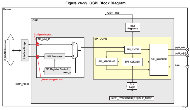
QSPI Block Diagram
Driver Architecture
Following diagram shows the QSPI driver stack:
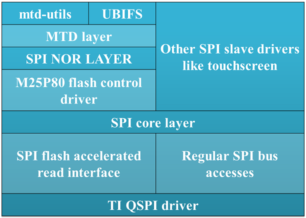
QSPI software stack
QSPI driver can be use both to access SPI flash devices via mtd subsystem or access generic SPI devices (like SPI touchscreen) via SPI framework.
Driver Configuration
Source Location
The source file for QSPI driver can be found at: drivers/spi/spi-ti-qspi.c under Linux kernel source tree.
Kernel Configuration Options
The driver can be built into the kernel or can be compiled as module and loaded into the kernel dynamically.
Enabling QSPI Driver Configurations
Following needs to be enabled to access QSPI flash: TI QSPI controller driver, SPI NOR framework and MTD M25P80 generic serial flash driver in the kernel via menuconfig.
start Linux Kernel Configuration tool.
$ make menuconfig ARCH=arm
To enable QSPI controller driver:
Device Drivers --->
[*] SPI support --->
<*> DRA7xxx QSPI controller support
To enable SPI NOR framework:
Device Drivers --->
<*> Memory Technology Device (MTD) support --->
<*> SPI-NOR device support --->
To enable M25P80 generic SPI flash driver:
Device Drivers --->
<*> Memory Technology Device (MTD) support --->
Self-contained MTD device drivers --->
<*> Support most SPI Flash chips (AT26DF, M25P, W25X, ...)
To enable them as module make <*> as <M>
Enabling UBIFS filesystem support:
File systems --->
[*] Miscellaneous filesystems --->
<*> UBIFS file system support
DT Configuration
Refer to Documentation/devicetree/bindings/spi/ti_qspi.txt under kernel source tree for QSPI controller driver’s DT bindings and their usage.
For generic SPI bus related DT bindings refer to: Documentation/devicetree/bindings/spi/ti_qspi.txt
To configure QSPI flash partitions and flash related DT bindings refer to: Documentation/devicetree/bindings/mtd/jedec,spi-nor.txt and Documentation/devicetree/bindings/mtd/partition.txt
Driver Usage
Load QSPI module using modprobe (this will take care of dependencies and load those modules as well)
$modprobe spi-ti-qspi
This should create /dev/mtdX entries for every partitions defined in DT or via command line arguments. To see all MTD partitions in the system run:
$cat /proc/mtd
dev: size erasesize name
mtd0: 00080000 00010000 "QSPI.U_BOOT"
mtd1: 00080000 00010000 "QSPI.U_BOOT.backup"
mtd2: 00010000 00010000 "QSPI.U-BOOT-SPL_OS"
mtd3: 00010000 00010000 "QSPI.U_BOOT_ENV"
mtd4: 00010000 00010000 "QSPI.U-BOOT-ENV.backup"
mtd5: 00800000 00010000 "QSPI.KERNEL"
mtd6: 036d0000 00010000 "QSPI.FILESYSTEM"
Testing
Using mtd-utils
$ cat /proc/mtd /* Should list QSPI partitions */
$ flash_erase /dev/mtd6 0 0 /* Erase entire /dev/mtd6 */
$ dd if=/dev/random of=tmp_write.txt bs=1 count=num /* num = bytes to write to flash */
$ mtd_debug write /dev/mtd6 0 num tmp_write.txt /* write to num bytes to flash */
$ mtd_debug read /dev/mtd6 0 num tmp_read.txt /* /* read to num bytes to flash */
$ diff tmp_read.txt tmp_write.txt /* should be NULL */
Using dd command
$ cat /proc/mtd /* Should list QSPI partitions */
$ flash_erase /dev/mtd6 0 0 /* Erase entire /dev/mtd6 */
$ dd if=/dev/random of=tmp_write.txt bs=1 count=num /* num = bytes to write to flash */
$ dd if=tmp_write.txt of=/dev/mtd6 bs=num count=1 /* write to num bytes to flash */
$ dd if=/dev/mtd6 of=tmp_read.txt bs=num count=1 /* read to num bytes to flash */
$ diff tmp_read.txt tmp_write.txt /* should be NULL */
Using UBIFS on flash
Make sure UBIFS filesystem is enabled in the kernel refer to this section.
root~# ubiformat /dev/mtd9
ubiformat: mtd9 (nor), size 23199744 bytes (22.1 MiB), 354 eraseblocks of 65536 bytes (64.0 KiB), min. I/O size 1 bytes
libscan: scanning eraseblock 353 -- 100 % complete
ubiformat: 354 eraseblocks are supposedly empty
ubiformat: formatting eraseblock 353 -- 100 % complete
root:~# ubiattach -p /dev/mtd9
[ 270.874428] ubi0: attaching mtd9
[ 270.914131] ubi0: scanning is finished
[ 270.921788] ubi0: attached mtd9 (name "QSPI.file-system", size 22 MiB)
[ 270.928405] ubi0: PEB size: 65536 bytes (64 KiB), LEB size: 65408 bytes
[ 270.935210] ubi0: min./max. I/O unit sizes: 1/256, sub-page size 1
[ 270.941491] ubi0: VID header offset: 64 (aligned 64), data offset: 128
[ 270.948102] ubi0: good PEBs: 354, bad PEBs: 0, corrupted PEBs: 0
[ 270.954215] ubi0: user volume: 0, internal volumes: 1, max. volumes count: 128
[ 270.961602] ubi0: max/mean erase counter: 0/0, WL threshold: 4096, image sequence number: 2077421476
[ 270.970887] ubi0: available PEBs: 350, total reserved PEBs: 4, PEBs reserved for bad PEB handling: 0
[ 270.980204] ubi0: background thread "ubi_bgt0d" started, PID 863
UBI device number 0, total 354 LEBs (23154432 bytes, 22.1 MiB), available 350 LEBs (22892800 bytes, 21.8 MiB), LEB size 65408 bytes (63.9 KiB)
root:~# ubimkvol /dev/ubi0 -N flash_fs -s 20MiB
Volume ID 0, size 321 LEBs (20995968 bytes, 20.0 MiB), LEB size 65408 bytes (63.9 KiB), dynamic, name "flash_fs", alignment 1
root:~# mkdir /mnt/flash
root:~# mount -t ubifs ubi0:flash_fs /mnt/flash/
[ 326.002602] UBIFS (ubi0:0): default file-system created
[ 326.008309] UBIFS (ubi0:0): background thread "ubifs_bgt0_0" started, PID 866
[ 326.027530] UBIFS (ubi0:0): UBIFS: mounted UBI device 0, volume 0, name "flash_fs"
[ 326.035157] UBIFS (ubi0:0): LEB size: 65408 bytes (63 KiB), min./max. I/O unit sizes: 8 bytes/256 bytes
[ 326.044615] UBIFS (ubi0:0): FS size: 20341888 bytes (19 MiB, 311 LEBs), journal size 1046528 bytes (0 MiB, 16 LEBs)
[ 326.055123] UBIFS (ubi0:0): reserved for root: 960797 bytes (938 KiB)
[ 326.061610] UBIFS (ubi0:0): media format: w4/r0 (latest is w4/r0), UUID 828AA98E-3A51-4B35-AD50-9E90144AD4C7, small LPT model
root:~#
Now you can access filesystem at /mnt/flash/
Limitations
- The QSPI supports only dual and quad reads. Dual or quad writes are not supported. In addition, there is no “pass through” mode supported where the data present on the QSPI input is sent to its output
- QSPI IP is designed in such a way that after 4096 word transfer, chip select automatically gets de asserted. As a result of which, the entire flash cannot be read in a single chip select using (Single/Dual/Quad) bit read mode feature. While the serial flash linux framework and flash specification expects the entire read to happen with a single read command in a single chip select. This limitation is not applicable when QSPI is used in memory mapped mode for reads. The QSPI driver by default uses memory mapped reads.
- For writes QSPI uses normal SPI interface instead of memory mapped mode, this is because there is an explicit write enable command that needs to be sent to flash for every page write (256 bytes) which is not handled by SPI_MM_IF.
3.3.4.20. RapidIO
Introduction
The Keystone 2 Hawking/Kepler (K2HK) SoC includes a RapidIO subsystem. This subsystem consists of the a Serial RapidIO module, a 4 lane SerDes macro, CPDMA and local SCR. The SRIO subsystem is compliant with SRIO 2.1 specification.
RapidIO Driver
The Keystone Linux RapidIO driver is integrated into the Linux RapidIO master port (mport) subsystem. It supports RIONET and DirectIO (one-to-one memory mapping).
Driver Source Location
Driver files are located in Linux kernel source directory drivers/rapidio/devices/. They are:
- keystone_rio.c
- keystone_rio_dma.c
- keystone_rio_mp.c
- keystone_rio_serdes.c
Kernel Configuration
To enable support of RapidIO in the K2HK kernel build, the following features must be set in the kernel configuration file (.config)
CONFIG_HAS_RAPIDIO=y
CONFIG_RAPIDIO=y
CONFIG_TI_KEYSTONE_RAPIDIO=y
CONFIG_RAPIDIO_DISC_TIMEOUT=200
CONFIG_RAPIDIO_ENABLE_RX_TX_PORTS=y
CONFIG_RAPIDIO_DMA_ENGINE=y
CONFIG_RAPIDIO_DEV=y
CONFIG_RAPIDIO_ENUM_BASIC=y
CONFIG_RAPIDIO_MPORT_CDEV=y
CONFIG_RIONET=y
CONFIG_RIONET_TX_SIZE=128
CONFIG_RIONET_RX_SIZE=128
Devicetree Configurations
Normally most of the RapidIO devicetree entries need not be changed for a normal usage.
Some entries under ‘rapidio: rapidio@2900000‘ in arch/arm/boot/dts/keystone-k2hk-srio.dtsi can be configured for your usage:
- baudrate = <baudrate_mode>; where baudrate can have the following values 0 (1.25Gbps), 1 (2.5Gbps), 2 (3.125Gbps) and 3 (5Gbps)
- path_mode = <path_mode>; where path_mode refers to the various SerDes-lanes-to-port mapping modes. Refer to the peripheral’s Keystone Architecture Serial RIO User Guide for more information. The most useful modes are 0 (1 port in 1x) or 4 (1 port in 4x).
- ports = <port_bitfield>; where port_bitfield indicates the mapping of ports we want to use in Linux to SerDes lanes. It is recommended to use only one port (0x1, 0x2, 0x4, 0x8 values) because multi-port is not fully supported yet.
Kernel command line parameters
The Linux RapidIO framework needs to set some specific parameters into the Linux command line (through U-Boot).
- rapidio.hdid=<host_id>[,<host_id2>,...]
- this parameter is used to define the host device Id. A host_id value greater or equal to zero indicates that this host will perform enumeration of the whole RapidIO topology using the host_id device Id. A ‘-1’ value indicates that no device Id will be set and the host will wait for being enumerated by a remote device then it will discover the RapidIO topology. In case of multiple mport instances, a list of host device Id can be specified.
- rio-scan.scan=<boolean>
- if explicitly set to 1 the scanning (discovery/enumeration) will be performed at boot time. If set to 0 (which is the default value if this parameter is not specified), the scanning must be triggered by user.
- rio-scan.static_enum=<boolean>
- this parameter allows to use static enumeration if set to 1. By default this parameter is set to 0. Static enumeration allows to discover the RapidIO topology without waiting for being enumerated by a remote host and using the remote host id instead of dynamically creating one like with standard enumeration.
If you want to perform scanning at boot time the recommended kernel parameters are
EVM1: 'rapidio.hdid=0 rio-scan.scan=1'
EVM2: 'rapidio.hdid=-1 rio-scan.scan=1'
In this case the EVM2 must be booted before EVM1. No need to wait EVM2 to fully complete its boot but at least few seconds are necessary to ensure that EVM2 port will be activated when EVM1 starts testing it.
Note that you can still rescan the full sRIO bus from userspace after boot by typing the following command on the both targets:
echo '-1' > /sys/bus/rapidio/scan
If you want to perform scanning from user space, the recommended kernel parameters are:
EVM1: 'rapidio.hdid=-1 rio-scan.scan=0'
EVM2: 'rapidio.hdid=0 rio-scan.scan=0'
Once the two boards are booted, trigger the scanning (enumeration/discovery) from user space on both boards using the following command:
echo '-1' > /sys/bus/rapidio/scan
In this case, there is no requirements on the order in which the boards must be booted.
MPORT Character Device
The character device implemented by Linux RapidIO mport subsystem provides character device read/write and some IOCtl operations to
- read/write local and remote RapidIO configuration registers
- send Doorbells
- perform DirectIO
See Documentation/rapidio/mport_cdev.txt in Linux kernel source code for more details.
Using RIONET
After booting up both EVMs, you must see boot traces similar to the following:
[ 11.938748] eth6: rionet Ethernet over RapidIO Version 0.3, MAC 00:01:00:01:00:00, RIO0 mport
[ 11.945718] Using 00:e:0002 (vid 0030 did b981)
[ 11.949829] keystone-rapidio 2900000.rapidio: Opened tx channel: ed9c5a34
[ 11.955693] keystone-rapidio 2900000.rapidio: Opened rx channel: ed9c5e34 (mbox=1, flow=19, rx_q=8715, pkt_type=11)
On EVM1 run the following command:
ifconfig eth6 192.168.1.1
You must substitute ‘eth6’ with the interface that corresponds to the MAC address 00:01:00:01:00: 00 (check by performing command “ifconfig -a”)
On EVM2 run the following command:
ifconfig eth6 192.168.1.2
You must substitute eth6 with the interface that corresponds to MAC address 00:01:00:01:00: 01
You can then use “ping 192.168.1.2” on EVM1 or “ping 192.168.1.1” on EVM2. Make sure that ping receives responses successfully.
On EVM2, run the command “telnet 192.168.1.1”. Make sure that the telnet session can be opened successfully. Ping and telnet can be performed on either EVM as long as the appropriate remote IP address is used in the command.
Using DirectIO
Once both boards have been booted and the RapidIO bus has been enumerated, the scanned remote ID can be used in performing DirectIO operation. The following sample code demonstrate how to use DirectIO to send a file to another K2HK EVM.
This example sends a file named “filename” to address 0x80000000 on a remote K2HK EVM with RapidIO device ID 1.
struct rio_transaction tran;
struct rio_transfer_io xfer;
int mport_fd, input_fd;
u16 target_destid;
u32 target_addr;
char *buf;
mport_fd = open(/dev/rio_mport0, O_RDWR | O_CLOEXEC | oflags);
target_destid = 1;
target_addr = 0x80000000;
input_fd = ("filename", O_RDONLY);
buf = malloc(1024 * 1024);
i = 0;
total = 0;
dst_off = 0;
while((ret_in = read (input_fd, buf, 4 * 1024)) > 0){
xfer.rioid = target_destid;
xfer.rio_addr = target_addr + dst_off;
xfer.loc_addr = buf;
xfer.length = ret_in;
xfer.handle = 0;
xfer.offset = 0;
xfer.method = RIO_EXCHANGE_NWRITE_R;
tran.transfer_mode = RIO_TRANSFER_MODE_TRANSFER;
tran.sync = RIO_TRANSFER_SYNC
tran.dir = RIO_TRANSFER_DIR_WRITE;
tran.count = 1;
tran.block = &xfer;
ioctl(mport_fd, RIO_TRANSFER, &tran);
dst_off += ret_in;
++i;
}
Using Doorbells
The following sample snippet sends a doorbell with a doorbell info value of 0x0002 to a remote K2HK EVM with RapidIO device ID 1.
Note: The 16-bit RapidIO doorbell info is hardware implementation specific. On TI’s RapidIO module, each bit of the 16-bit value is mapped to an interrupt. By the default configuration in the devicetree bindings, these interrupts are mapped to the 16 interrupts starting from 153. Thus bit-0 in the doorbell info will trigger the interrupt 153, while bit-1 will trigger interrupt 154 and so on, on the remote K2HK EVM.
struct rio_event sevent;
u16 target_destid;
u16 db_info;
char *p = (char*)&sevent;
unsigned int len = 0;
mport_fd = open("/dev/rio_mport0", O_RDWR | O_CLOEXEC | oflags);
target_destid = 1;
db_info = 0x0002;
sevent.header = RIO_DOORBELL;
sevent.u.doorbell.rioid = target_destid;
sevent.u.doorbell.payload = db_info;
while (len < sizeof(sevent)) {
ret = write(mport_fd, p + len, sizeof(sevent) - len);
len += ret;
}
3.3.4.21. SPI
Introduction
- Serial interface
- Synchronous
- Master-slave configuration (driver supports only master mode)
- Data Exchange - DMA/PIO
SOC Specific Information
| SoC Family | Driver |
|---|---|
| AM335x | McSPI |
| AM437x | McSPI |
| DRA7x | McSPI |
| 66AK2Gx | McSPI |
| 66AK2Lx | Davinci |
| 66AK2Hx | Davinci |
| 66AK2E | Davinci |
Features Not Supported
SoCs using McSPI driver
SPI slave mode isn’t supported
SoCs using Davinci Driver
SPI slave mode isn’t supported
Kernel Configuration
The specific peripheral driver to enable depends on the SoC being used.
Enabling McSPI Driver
Device Drivers --->
[*] SPI support
[*] McSPI driver for OMAP
Enabling DaVinci Driver
Device Drivers --->
[*] SPI support
[*] Texas Instruments DaVinci/DA8x/OMAP-L/AM1x SoC SPI controller
SPI Driver Usecases
There are numerous drivers that can be used to interact with a variety of hardware. From SPI based RTC to SPI based GPIO expander. A list of drivers along with their documentation can be found within the kernel sources. The below section attempts to provide information on SPI based chips that are located on TI’s evms.
Flash Storage
Boards with SPI Flash
| EVM | Part # | Flash Size |
|---|---|---|
| AM335x ICE EVM | W25Q64 | 8 MB |
| K2E EVM | N25Q128A11ESF40F | 16 MB |
| K2HK EVM | N25Q128A11ESF40F | 16 MB |
| K2L EVM | N25Q128A11ESF40F | 16 MB |
Kernel Configuration
Device Drivers --->
<*> Memory Technology Device (MTD) support --->
Self-contained MTD device drivers --->
<*> Support most SPI Flash chips (AT26DF, M25P, W25X, ...)
Reading/Writing to Flash
Determine SPI NOR Partition MTD Identifier
Within the kernel figuring out the mtd device number that is for a particular SPI NOR partition is simple. A user simply needs to view the list of mtd devices along with its name. Below command will provide this information:
cat /proc/mtd
An example of this output performed on the AM571x IDK EVM can be seen below.
dev: size erasesize name
mtd0: 00040000 00010000 "QSPI.SPL"
mtd1: 00100000 00010000 "QSPI.u-boot"
mtd2: 00080000 00010000 "QSPI.u-boot-spl-os"
mtd3: 00010000 00010000 "QSPI.u-boot-env"
mtd4: 00010000 00010000 "QSPI.u-boot-env.backup1"
mtd5: 00800000 00010000 "QSPI.kernel"
mtd6: 01620000 00010000 "QSPI.file-system"
Note the names of these partitions, their sizes (in hex) and offsets (in hex) are determined within the specific board’s device tree file.
flash_erase /dev/mtdX 0 0
Where X is the partition number.
cd /tmp
dd if=/dev/mtd2 of=test.img bs=8k count=1
md5sum test.img
flash_eraseall /dev/mtd4
dd if=test.img of=/dev/mtd4 bs=8k count=1
dd if=/dev/mtd4 of=test1.img bs=8k count=1
md5sum test1.img
Linux Userspace Interface
In situations where a premade SPI driver doesn’t exist or a user wants a simple means to send and receive SPI messages the spidev driver can be used. Spidev provides a user space accessible means to communicate with the SPI interface. Latest documentation regarding spidev driver can be found here.
Spidev allows users to interact with the spi interface in a variety of programming languages that can communicate with kernel ioctls.
Kernel Configuration
Device Drivers --->
[*] SPI support
<*> User mode SPI device driver support
Device Tree
Below is an example of the device tree settings a user would use to enable the spidev driver. Like most drivers for a peripheral, the spidev driver is listed as a subnode of the main SPI peripheral driver.
&spi1 {
status = "okay";
pinctrl-names = "default";
pinctrl-0 = <&spi1_pins_s0>;
spidev@1 {
spi-max-frequency = <24000000>;
reg = <0>;
compatible = "rohm,dh2228fv";
};
};
- Note that reg property for SPI subnodes are usually used to indicate the chip select to use when communicating with a particular driver.
Test Application
In the kernel sources, ./tools/spi/spidev_test.c is a test application within the kernel that can be cross compiled to show a C application interacting with the SPI peripheral.
3.3.4.22. SATA
Introduction
Acronyms & Definitions
| Acronym | Definition |
|---|---|
| SATA | Serial Advanced Technology Attachement |
| PATA | Parallel AT Attachement |
| SSD | Solid State Disk |
| HDD | Hard Disk Drive |
| Gen-1/Gen-2/Gen-3 | Generation of SATA device. |
Features NOT supported
- Gen-3 SATA HDD/SSD is not guaranteed to be supported on OMAP5 and DRA7 due to a silicon bug which prevents correct PHY speed negotiation.
- Aggressive Power management
Supported EVMs
| EVM | Number of Instances |
|---|---|
| AM57 GP EVM | 1 Instance (either eSATA or mSATA) |
| Beagle X15 | 1 Instance (eSATA) |
| DRA74 GP EVM | 1 Instance (SATA) |
Table: caption
Kernel Configuration
Device Drivers --->
<M> Serial ATA and Parallel ATA drivers (libata) --->
<M> AHCI SATA support
<M> Platform AHCI SATA support
Accessing SATA Hard Drive
These instructions assume the SATA hard drive being used has already been partitions. Information on partition the hard drive is beyond the scope of this article.
Kernel
Detecting Hard Drive
Before you can start reading and writing to a partition you first need to know which sdX device is associate with the hard drive. The easiest approach is to use “parted -l”.
This command will show all the various storage medias Linux has detected. The output that will be shown may be quite large if you have sd cards, eMMC, USB thumbdrives, etc.. connected to the board. However, for SATA your only interested in devices that have “(scsi)” at the end of the Model field.
Example output of the command is shown below. Non SATA related output was truncated.
root@am57xx-evm:~# parted -l
...
Model: ATA PLEXTOR PX-64M6M (scsi)
Disk /dev/sda: 64.0GB
Sector size (logical/physical): 512B/512B
Partition Table: msdos
Disk Flags:
Number Start End Size Type File system Flags
1 1049kB 83.9MB 82.8MB primary fat32 boot, lba
2 84.9MB 17.3GB 17.2GB primary fat32
3 17.3GB 64.0GB 46.8GB primary ext2
...
Above the model field shows the name of the particular hard drive and in the disk field it shows the specific device (/dev/sdX) its associated with along with the size. In the above example this Plextor hard drive is associated with “/dev/sda”. The other additional information that can be gathered from the parted -l command is information regarding the various partitions. In the table that has column Number, Start, End, etc... you can see this hard drive has 3 partitions. The command shows various information including the partition size along with the file system type.
This is useful since each partition can be accessed via /dev/sdXY. Where X is the specific disk letter and Y is the partition number. Therefore, the device that is associated with the Plextor hard drive’s second partition is “/dev/sda2” which is a ~17GB FAT32 partition.
Determining Mounted Partition Location
Now its likely if you have partitions on the hard drive that their already been automated. Use “lsblk /dev/sdX” to determine if a partition has been mounted and if so where.
Example output of the command is shown below:
root@am57xx-evm:~# lsblk /dev/sda
NAME MAJ:MIN RM SIZE RO TYPE MOUNTPOINT
sda 8:0 0 59.6G 0 disk
|-sda2 8:2 0 16G 0 part /run/media/sda2
|-sda3 8:3 0 43.6G 0 part
`-sda1 8:1 0 79M 0 part /run/media/sda1
The above output shows the three sda partitions. Under mountpoint it list the directory that the partition has been mounted to. However, a blank entry under mount point indicates the partition has not been mounted.
U-Boot
Information regarding accessing SATA hard drive in U-boot can be found in the Linux Core U-boot User’s Guide SATA Section.
3.3.4.23. NAND
Introduction
TI infrastructure for NAND Flash devices
TI’s SoC interface with NAND Flash devices via on-chip GPMC (General Purpose Memory Controller) interface or via AEMIF depending on the SoC.
For devices that include GPMC: The ECC algorithms required by NAND devices to protect their data, are managed by two independent hardware engines:
- GPMC ECC engine: used for calculating ECC checksum while writing and reading the NAND device.
- ELM ECC engine: used for locating and decoding ECC errors while reading the NAND device.
- NAND subsystem: protocol driver in MTD sub-system for interfacing with NAND flash devices.
For K2L and K2E:
- AEMIF driver: controller driver for AEMIF engine
For all other SoCs:
- GPMC driver: controller driver for GPMC engine
- ELM driver (for applicable SoC) : controller driver for ELM engine.
Supported Features
- NAND devices having:
- bus-width = x8 | x16
- page-size = 2048 | 4096
- block-size = 128k | 256k
- 1-bit Hamming, BCH4, BCH8 and BCH16 ECC schemes.
- Various transfer modes for different use-cases and applications (like Polled, Polled Prefetch, IRQ and DMA).
- NAND boot support for custom non-ONFI compatible NAND devices using NAND-I2C boot-mode (Refer Chapter on Initialization in processor’s TRM).
- Sub-page write
Accessing NAND partitions
Linux
Within the kernel NAND partitions are accessed via mtd devices. Instead are referring to a partition by its name or its offset a user simply needs to specify the NAND partition in question in the form of its mtd device path. Usually in the format of /dev/mtdX where X is the mtd device number.
Determine NAND Partition MTD Identifier
Within the kernel figuring out the mtd device number that is for a particular NAND partition is simple. A user simply needs to view the list of mtd devices along with its name. Below command will provide this information:
cat /proc/mtd
An example of this output performed on the DRA71x EVM can be seen below.
dev: size erasesize name
mtd0: 00010000 00010000 "QSPI.SPL"
mtd1: 00010000 00010000 "QSPI.SPL.backup1"
mtd2: 00010000 00010000 "QSPI.SPL.backup2"
mtd3: 00010000 00010000 "QSPI.SPL.backup3"
mtd4: 00100000 00010000 "QSPI.u-boot"
mtd5: 00080000 00010000 "QSPI.u-boot-spl-os"
mtd6: 00010000 00010000 "QSPI.u-boot-env"
mtd7: 00010000 00010000 "QSPI.u-boot-env.backup1"
mtd8: 00800000 00010000 "QSPI.kernel"
mtd9: 01620000 00010000 "QSPI.file-system"
mtd10: 00020000 00020000 "NAND.SPL"
mtd11: 00020000 00020000 "NAND.SPL.backup1"
mtd12: 00020000 00020000 "NAND.SPL.backup2"
mtd13: 00020000 00020000 "NAND.SPL.backup3"
mtd14: 00040000 00020000 "NAND.u-boot-spl-os"
mtd15: 00100000 00020000 "NAND.u-boot"
mtd16: 00020000 00020000 "NAND.u-boot-env"
mtd17: 00020000 00020000 "NAND.u-boot-env.backup1"
mtd18: 00800000 00020000 "NAND.kernel"
mtd19: 0f600000 00020000 "NAND.file-system"
As you can see above the list of mtd devices may not only include NAND partitions but list other peripherals that create mtd devices also. From the above you can see that if the user wants to access the file-system partition within the NAND then they use /dev/mtd19 to reference the partition. The names of these partitions, their sizes (in hex) and offsets (in hex) are determined within the specific board’s device tree file.
Erasing, Reading and Writing
For the below sections it is important to remember to replaced mtdX with the mtd device that is associated with the particular NAND partition as described in the above section.
flash_erase /dev/mtdX 0 0
The command to write to a NAND partition is below:
nandwrite -p /dev/mtdX <filename>
nanddump /dev/mtdX -f <filename>
The symbol <filename> should be replaced with the name of a file you want to be created that contains with contents of the NAND partition. Note that the above command by default with save to a file the complete contents of the NAND partition. If your interested in only a certain amount of data being dumped additional parameters can be passed to the utility.
Command Line Partitioning
In some situations, partitions defined in device-tree may not be sufficient or correct. Note that once partitions are defined in device-tree and present in a mainline kernel release, they cannot be changed because this breaks users who have existing data on NAND flash and upgrade to new kernel and device-tree. If you are not affected by this issue, you may choose to override partition information passed from device-tree using command line.
In TI kernel releases, MTD command line partitioning support is built as module. To use it, add something like following to the kernel command line (passed using bootargs U-Boot variable)
setenv bootargs ${bootargs} cmdlinepart.mtdparts=davinci-nand.0:1m(image)ro,-(free-space)
Note that MTD command line parses breaks if there is space in partition name. So use “free-space” not “free space”. Change davinci-nand.0 to the correct device name. You can usually find the name to use from dmesgoutput
Creating 2 MTD partitions on "davinci-nand.0":
You can also setup new partitions after kernel has booted with old partitions. You will need to re-probe the NAND driver if it has already probed. Something like:
$ modprobe -r davinci_nand
$ modprobe cmdlinepart mtdparts="davinci-nand.0:2m(image)ro,-(free space)"
$ modprobe davinci_nand
davinci_nand module name here may have to be changed based on the SoC you are using.
U-boot
NAND Based File system
Required Software
Building a UBI file system depends on two applications. Ubinize and mkfs.ubifs which are both provided by Ubuntu’s mtd-utils package (apt-get install mtd-utils). The below instructions are based on version 1.5.0 of mtd-utils although newer version are likely to work.
Building UBI File system
When building a UBI file system you need to have a directory that contains the exact files and directories layout that you plan to use for your file system. This is similar to the files and directories layout you will use to copy a file system onto a SD card for booting purposes. It is important that your file system size is smaller than the file system partition in the NAND.
[ubifs]
mode=ubi
image=<name>.ubifs
vol_id=0
vol_type=dynamic
vol_name=rootfs
vol_flags=autoresize
mkfs.ubifs -r <directory path> -o <name>.ubifs <MKUBIFS ARGS>
ubinize -o <name>.ubi <UBINIZE ARGS> ubinize.cfg
Once these commands are executed <name>.ubi can then be programmed into the NAND’s designated file-system partition.
| Board Name | MKUBIFS Args | UBINIZE Args |
|---|---|---|
| AM335X GP EVM | -F -m 2048 -e 126976 -c 5600 | -m 2048 -p 128KiB -s 512 -O 2048 |
| AM437x GP EVM | -F -m 4096 -e 253952 -c 2650 | -m 4096 -p 256KiB -s 4096 -O 4096 |
| K2E EVM | -F -m 2048 -e 126976 -c 3856 | -m 2048 -p 128KiB -s 2048 -O 2048 |
| K2L EVM | -F -m 4096 -e 253952 -c 1926 | -m 4096 -p 256KiB -s 4096 -O 4096 |
| K2G EVM | -F -m 4096 -e 253952 -c 1926 | -m 4096 -p 256KiB -s 4096 -O 4096 |
| DRA71x EVM | -F -m 2048 -e 126976 -c 8192 | -m 2048 -p 128KiB -s 512 -O 2048 |
Table: Table of Parameters to use for Building UBI filesystem image
Board specific configurations
| EVM | NAND Part # | Size | Bus-Widt h | Block-Si ze (KB) | Page-Siz e (KB) | OOB-Size (bytes) | ECC Scheme | Hardware |
|---|---|---|---|---|---|---|---|---|
| AM335x GP | MT29F2G0 8AB | 256 MB | 8 | 128 | 2 | 64 | BCH 8 | GPMC |
| AM437x GP | MT29F4G0 8AB | 512 MB | 8 | 256 | 4 | 224 | BCH 16 | GPMC |
| AM437x EPOS | MT29F4G0 8AB | 512 MB | 8 | 256 | 4 | 224 | BCH 16 | GPMC |
| DRA71x | MT29F2G1 6AADWP:D | 256 MB | 16 | 128 | 2 | 64 | BCH 8 | GPMC |
| K2G | MT29F2G1 6ABAFAWP :F | 512 MB | 16 | 128 | 2 | 64 | BCH 16 | GPMC |
| K2E | MT29F4G0 8ABBDAH4 D | 1 GB | 8 | 128 | 2 | 64 | TBD | AEMIF |
| K2L | MT29F16G 08ADBCAH 4:C | 512 MB | 8 | 256 | 4 | 224 | TBD | AEMIF | |
Table: NAND Flash Specification Summary
AM43xx GP EVM
On this board, NAND Flash data lines are muxed with eMMC, so either eMMC or NAND can be used enabled at a time. By default NAND is enabled.
AM43xx EPOS EVM
On this board, NAND Flash control lines are muxed with QSPI, Thus either NAND or QSPI-NOR can be used at a time. By default NAND is enabled.
DRA71x EVM
On the board, NAND Flash signals are muxed between NAND, NOR and Video Out signals. Therefore, to have the signals properly muxed for NAND to work Pin 1 (first pin on the left) must be turned on and Pin 2 must be turned off. Pin 1 and 2 must never be switched on at the same time. Doing so may cause damage to the board or SoC.
Configurations (GPMC Specific)
How to enable OMAP NAND driver in Linux Kernel ?
OMAP NAND driver can be enable/disable via Linux Kernel Configuration tool. Enable below Configs to enable MTD Support along with MTD nand driver support
Device Drivers --->
<*> Memory Technology Device (MTD) support --->
[*] Command line partition table parsing
<*> Direct char device access to MTD devices
<*> Caching block device access to MTD devices
<*> NAND Device Support --->
<*> NAND Flash device on OMAP2 and OMAP3
<*> Enable UBI - Unsorted block images --->
Transfer Modes
Choose correct bus transfer mode
- “prefetch-polled” Prefetch polled mode (default)
- “polled” Polled mode, without prefetch
- “prefetch-dma” Prefetch enabled DMA mode
- “prefetch-irq” Prefetch enabled IRQ mode
Transfer mode can be configured in linux-kernel via DT binding <ti,nand-xfer-type> Refer: Linux kernel_docs @ $LINUX/Documentation/devicetree/bindings/mtd/gpmc-nand.txt
DMA vs Non DMA Mode (PIO Mode)
The current NAND subsystem within Linux currently deals with reading a single page from the NAND at a time. Unfortunately, the page size is small enough that the overhead for using the DMA (including Linux DMA software stack) negatively impacts the performance. Based on nand performance tests done in early 2016 using the DMA reduced NAND read and write performance by 10-20% depending on SOC. However, cpu load when using polling via the same NAND test were around 99%. When using DMA mode the CPU load for reading was around 35%-54% and for writing was around 15%-30% depending on SOC.
Performance optimizations on NAND
Tweak NAND device signal timings
Much of the NAND throughput can be improved by matching GPMC signal timings with NAND device present on the board. Although GPMC signal timing configurations are not same as those given in NAND device datasheets, but they can be easily derived based on details given in GPMC Controller functional specification.
- Details of GPMC Signal Timing configurations and how to use them can be found in TI’s Processor TRM
Chapter General Purpose Memory Controller Section Signal Control
- In Linux, GPMC signal timing configurations are specified via DTB.
Refer kernel_docs $LINUX/Documentation/devicetree/bindings/bus/ti-gpmc.txt Some timing configurations like <gpmc,rd-cycle-ns>, <gpmc,wr-cycle-ns> have larger impact on NAND throughput than others.
- In U-boot, GPMC signal timing configurations are specified during GPMC initialization in arch/arm/cpu/armv7/../... mem.c or mem_common.c
gpmc_init() :: struct gpmc_cfg
Tweaking UBIFS
- Specify -o bulk_read while mounting UBIFS (read ahead)
- Tweak Linux VM (kernel knobs for VM)
Additional Resources
3.3.4.24. MMC/SD
Introduction
The multimedia card high-speed/SDIO (MMC/SDIO) host controller provides an interface between a local host (LH) such as a microprocessor unit (MPU) or digital signal processor (DSP) and either MMC, SD® memory cards, or SDIO cards and handles MMC/SDIO transactions with minimal LH intervention.
Main features of the MMC/SDIO host controllers:
- Full compliance with MMC/SD command/response sets as defined in the Specification.
- Support:
- 4-bit transfer mode specifications for SD and SDIO cards
- 8-bit transfer mode specifications for eMMC
- Built-in 1024-byte buffer for read or write
- 32-bit-wide access bus to maximize bus throughput
- Single interrupt line for multiple interrupt source events
- Two slave DMA channels (1 for TX, 1 for RX)
- Designed for low power and Programmable clock generation
- Maximum operating frequency of 48MHz
- MMC/SD card hot insertion and removal
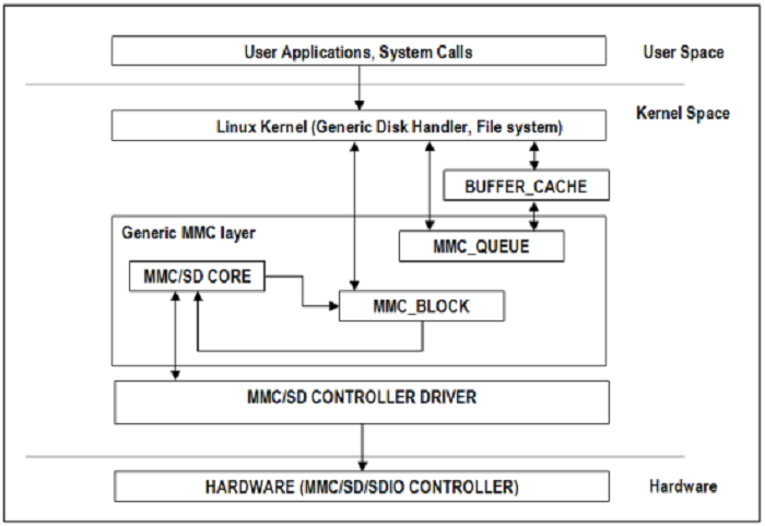
MMC/SD Driver Architecture
References
- JEDEC eMMC Homepage [https://www.jedec.org/category/technology-focus-area/flash-memory-ssds-ufs-emmc]
- SD ORG Homepage [https://www.sdcard.org/home]
Acronyms & Definitions
| Acronym | Definition |
|---|---|
| MMC | Multimedia Card |
| HS-MMC | High Speed MMC |
| SD | Secure Digital |
| SDHC | SD High Capacity |
| SDIO | SD Input/Output |
Table: HSMMC Driver: Acronyms
Features
The SD driver supports following features
- The driver is built in-kernel (part of vmlinux)
- SD cards including SD High Speed and SDHC cards
- Uses block bounce buffer to aggregate scattered blocks
Features NOT supported
- Polling I/O mode
Supported High Speed Modes
| Platform | SDR104 | DDR50 | SDR50 | SDR25 | SDR12 |
|---|---|---|---|---|---|
| DRA74-EVM | Y | Y | Y | Y | Y |
| DRA72-EVM | Y | Y | Y | Y | Y |
| DRA71-EVM | Y | Y | Y | Y | Y |
| DRA72-EVM-REVC | Y | Y | Y | Y | Y |
| AM57XX-EVM | N | N | N | N | N |
| AM57XX-EVM-REVA3 | Y*(1)* | Y*(1)* | Y*(1)* | Y*(1)* | Y*(1)* |
| AM572X-IDK | Y*(1)* | Y*(1)* | Y*(1)* | Y*(1)* | Y*(1)* |
| AM571X-IDK | Y*(1)* | Y*(1)* | Y*(1)* | Y*(1)* | Y*(1)* |
Table: MMC1/SD
*(1)* - Does not have power cycle support. So if a card fails to enumerate in UHS mode, it doesn’t fall back to high speed mode.
Important Info: Certain UHS cards doesn’t enumerate in UHS cards. Find the list of functional UHS cards here: https://processors.wiki.ti.com/index.php/Linux_Core_MMC/SD_User%27s_Guide#Testing_Information
Known Workaround: For cards which doesn’t enumerate in UHS mode, removing the PULLUP resistor in CLK line and changing the GPIO to PULLDOWN increases the frequency in which the card enumerates in UHS modes.
| Platform | DDR | HS200 |
|---|---|---|
| DRA74-EVM | Y | Y |
| DRA72-EVM | Y | Y |
| DRA71-EVM | Y | Y |
| DRA72-EVM-REVC | Y | Y |
| AM57XX-EVM | Y | N |
| AM57XX-EVM-REVA3 | Y | N |
| AM572X-IDK | Y | N |
| AM571X-IDK | Y | N |
Table: MMC2/EMMC
Driver Configuration
The default kernel configuration enables support for MMC/SD(built-in to kernel). OMAP MMC/SD driver is used.
The selection of MMC/SD/SDIO driver can be modified as follows: start Linux Kernel Configuration tool.
$ make menuconfig ARCH=arm
- Select Device Drivers from the main menu.
...
...
Kernel Features --->
Boot options --->
CPU Power Management --->
Floating point emulation --->
Userspace binary formats --->
Power management options --->
[*] Networking support --->
Device Drivers --->
...
...
Building into Kernel
- Select MMC/SD/SDIO card support from the menu.
...
...
[*] USB support --->
< > Ultra Wideband devices (EXPERIMENTAL) --->
<*> MMC/SD/SDIO card support --->
< > Sony MemoryStick card support (EXPERIMENTAL) --->
...
...
- Select OMAP HSMMC driver
...
[ ] MMC debugging
[ ] Assume MMC/SD cards are non-removable (DANGEROUS)
*** MMC/SD/SDIO Card Drivers ***
<*> MMC block device driver
[*] Use bounce buffer for simple hosts
...
<*> TI OMAP High Speed Multimedia Card Interface support
...
Building as Loadable Kernel Module
- To build the above components as modules, press ‘M’ key after navigating to config entries preceded with ‘< >’ as shown below:
...
...
[*] USB support --->
< > Ultra Wideband devices (EXPERIMENTAL) --->
<M> MMC/SD/SDIO card support --->
< > Sony MemoryStick card support (EXPERIMENTAL) --->
...
- Select OMAP HSMMC driver to be built as module
...
[ ] MMC debugging
[ ] Assume MMC/SD cards are non-removable (DANGEROUS)
*** MMC/SD/SDIO Card Drivers ***
<*> MMC block device driver
[*] Use bounce buffer for simple hosts
...
<*> TI OMAP High Speed Multimedia Card Interface support
...
- After doing module selection, exit and save the kernel configuration when prompted.
- Now build the kernel and modules form Linux build host as
$ make uImage
$ make modules
- Following modules will be built
mmc_core.ko
mmc_block.ko
omap_hsmmc.ko
- Boot the newly built kernel and transfer the above mentioned .ko files to the filesystem
- Navigate to the directory containing these modules and insert them form type the following commands in console to insert the modules in specified order:
# insmod mmc_core.ko
# insmod mmc_block.ko
# insmod omap_hsmmc.ko
- If ‘udev’ is running and the SD card is already inserted, the devices nodes will be created and filesystem will be automatically mounted if exists on the card.
Suspend to Memory support
This driver supports suspend to memory functionality. To use the same, the following configuration is enabled by default.
- Select Device Drivers from the main menu.
...
...
Kernel Features --->
Boot options --->
CPU Power Management --->
Floating point emulation --->
Userspace binary formats --->
Power management options --->
[*] Networking support --->
Device Drivers --->
...
...
- Select MMC/SD/SDIO card support from the menu.
...
...
[*] USB support --->
< > Ultra Wideband devices (EXPERIMENTAL) --->
<*> MMC/SD/SDIO card support --->
< > Sony MemoryStick card support (EXPERIMENTAL) --->
...
...
- Select Assume MMC/SD cards are non-removable option.
...
[ ] MMC debugging
[*] Assume MMC/SD cards are non-removable (DANGEROUS)
*** MMC/SD/SDIO Card Drivers ***
<*> MMC block device driver
[*] Use bounce buffer for simple hosts
...
<*> TI OMAP High Speed Multimedia Card Interface support
...
Enabling eMMC Card Background operations support
This can be done using the “mmc-utils” tool from user space or using the “mmc” command in U-boot.
Command to enable bkops from userspace using mmc-utils, assuming eMMC instance to be mmcblk0
root@dra7xx-evm:mmc bkops enable /dev/mmcblk0
You can find the instance of eMMC by reading the ios timing spec form debugfs
root@dra7xx-evm:~# cat /sys/kernel/debug/mmc0/ios
----
timing spec: 9 (mmc HS200)
---
or by looking for boot partitions, eMMC has two bootpartitions mmcblk<x>boot0 and mmcblk<x>boot1
root@dra7xx-evm:/# ls /dev/mmcblk*boot*
/dev/mmcblk0boot0 /dev/mmcblk0boot1
| FUNCTIONAL UHS CARDS |
|---|
| ATP 32GB UHS CARD AF32GUD3 |
| STRONTIUM NITRO 466x UHS CARD |
| SANDISK EXTREME UHS CARD |
| SANDISK ULTRA UHS CARD |
| SAMSUNG EVO+ UHS CARD |
| SAMSUNG EVO UHS CARD |
| KINGSTON UHS CARD (DDR mode) |
| TRANSCEND PREMIUM 400X UHS CARD (Non fatal error and then it re-enumerates in UHS mode) |
| FUNCTIONAL (WITH LIMITED CAPABILITY) UHS CARD |
|---|
| SONY UHS CARD - Voltage switching fails and enumerates in high speed |
| GSKILL UHS CARD - Voltage switching fails and enumerates in high speed |
| PATRIOT 8G UHS CARD - Voltage switching fails and enumerates in high speed |
3.3.4.25. UART
UART Driver Overview
The UART Driver enables the UART’s available on the device. The driver configures the UART hardware and interfaces with a number of standard linux tools (ex. stty, minicom, etc.) to enable the configuration and usage of the hardware. The H/W UARTs available will vary by SoC and system configuration.
Overview
The UART driver can be used to send/receive raw ASCII characters from the User Interface as shown by the below diagram.
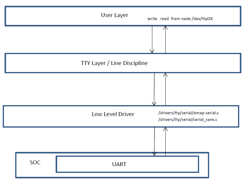
User Layer
The UART driver leverages the TTY framework within Linux. This framework uses typical file I/O operations to interact with the UART. This interface allows userspace modules to easily be developed to read/write the /dev/ttyxx to exchange data over the UART. Since this is a very common Linux framework, there are many standard tools that can be used to interact with it. These tools, like stty, minicom, picocom, and many others, can easily be used to exercise a UART for data exchange.
Features
- Exposes UART to User Space via /dev/tty*
- Supports multiple baud rates and UART capabilities
- Hardware Flow Control
3.3.4.26. MUSB
Quick Start Guide
This section is a quick guide on how to start using usb ports on TI platform with supplied pre-built binaries. Please refer to USB Quick Start
Introduction
The USB User’s Guide provides information about
- Overview of USB hardware and software
- Supported linux driver features for USB host and device mode of operation
- The Linux USB configuration through menuconfig. Please refer to USB configuration
Hardware Overview
USBSS Overview
- The USB subsystem includes
- Two instances of USB (Mentor Graphic’s USB2.0 OTG) controllers. Each MUSB controller supports USB 1.1 and USB 2.0 standard.
- CPPI 4.1 compliant DMA controller sub-module with 30 RX and 30 TX simultaneous DMA channels
- CPPI 4.1 DMA scheduler
- CPPI Queue Manager module with 92 queues for queuing/dequeuing packets
- Interfaces to the CPU via 3 OCP interfaces
- Master OCP HP interface for the DMA (for data transfers)
- Master OCP HP interface for the Queue manager (to manage CPPI descriptors)
- Slave OCP MMR interface (for CPU to access USBSS/MUSB registers)
- Signals the standard Charge Pump (part of EVM BOM) for VBUS 5V generation
MUSB Controller Overview
The salient features of the MUSB USB2.0 OTG controller are:
- High/full speed operation as USB peripheral.
- High/full/low speed operation as Host controller.
- Compliant with OTG spec.
- 15 Transmit and 15 Receive Endpoints other than the mandatory Control Endpoint 0.
- Double buffering support in FIFO.
- Support for high bandwidth Isochronous transfer
- 32 Kilobytes of Endpoint FIFO RAM for USB packet buffering.
- Interfaced with CPPI4.1 DMA controller with 15 Rx and 15 Tx channels (for each usb controller).
- Defer interrupt enable feature is supported for each packet descriptor of cppi-dma.
Software Overview
Mentor graphics controller driver (or MUSB driver)
The MUSB driver is implemented on top of Mentor controller IP which supports all the speeds (High, Full and Low). AM33XX USBOTG subsytem uses CPPI 4.1 DMA for all the transfers. The musb driver conforms to linux usb framework and supports both PIO and DMA mode of operation. The musb host controller driver (HCD) binds the controller hardware to linux usb core stack. The musb device or gadget controller driver binds the controller hardware and specific gadget driver (filestorage, cdc/rndis etc).
Linux USB Stack Architecture
As shown in the figure, linux usb stack is a layered architecture, with musb controller at the lowest layer, the musb host/device controller driver binds the musb controller hardware to linux usb stack framework. The CPPI4.1 DMA controller driver is responsible for transmit/receive of packets over the musb endpoints.
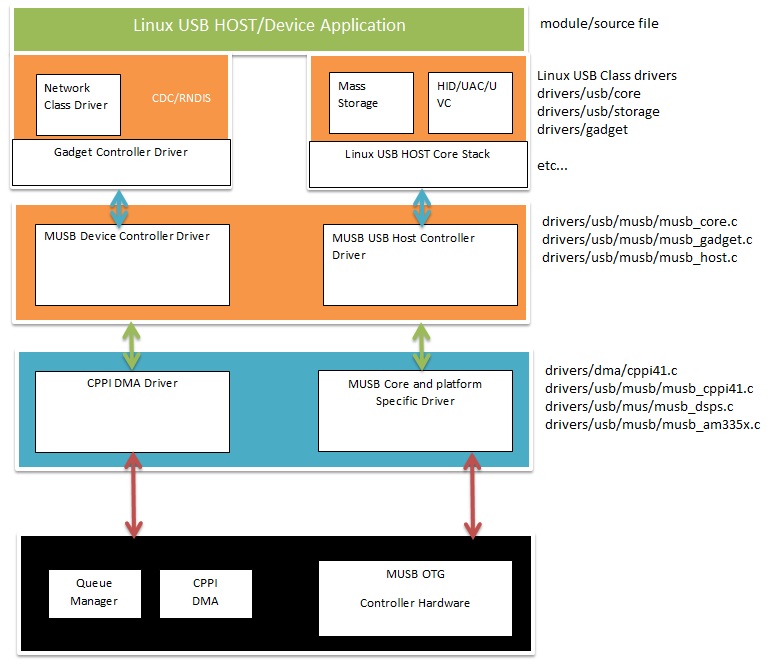
Driver Features List
- The Mentor USB driver can be built as module or built-in to kernel
- Support both PIO and DMA mode (The DMA mode not applicable for control endpoint)
- Support two instances musb controller in otg mode (both usb0 and usb1 controller in otg mode. This will allow host or device operation on each port simultaneously.
The driver supports the following features for USB Host (AM33XX)
| Host Mode Feature | AM33xx |
|---|---|
| HUB class support | Yes |
| Human Interface Class (HID) | Yes |
| Mass Storage Class (MSC) _ | Yes |
Table:
The driver supports the following features for USB Gadget (AM33XX)
| Gadget Mode Feature | AM33xx |
|---|---|
| Mass Storage Class (MSC) | Yes |
| USB Networking - RNDIS | Yes |
| USB Networking - CDC | Yes |
Table:
The driver supports the following features for Dual host/gadget (AM33xx)
| Dual Mode Feature | AM33x |
|---|---|
| USB0 as OTG, USB1 as OTG | Yes |
Table:
Not verified features of AM33xx
| Not verified features | am33x |
|---|---|
| Wifi support | Not verified |
| Serial device | Not verified |
Table:
Known limitations
- musb_am335x.ko can’t be removed (and we don’t allow that to happen) to workaround a known hwmod issue.
- multi-gadget cannot be used on OMAP-L138 because of lack of sufficient number of endpoints to support multiple functions
- high bandwidth ISO cannot be supported on OMAP-L138. On trying a high bandwidth ISO transfer, you should see message of the form:
musb-hdrc musb-hdrc.1.auto: high bandwidth iso (3x896) not supported
This behaviour is expected.
References
- For more details about EVM, please refer to EVM reference manual.
- The Mentor USB driver can be built as module or built into kernel. For more information refer to USB configuration
3.3.4.27. DWC3
Introduction
DWC3 is a SuperSpeed (SS) USB 3.0 Dual-Role-Device (DRD) from Synopsys.
Main features of DWC3:
The SuperSpeed USB controller features:
- Dual-role device (DRD) capability:
- Same programming model for SuperSpeed (SS), High-Speed (HS), Full-Speed (FS), and Low-Speed (LS)
- Internal DMA controller
- LPM protocol in USB 2.0 and U0, U1, U2, and U3 states for USB 3.0
TI SoC Integration
DWC3 is integrated in OMAP5, DRA7x and AM437x SoCs from TI.
OMAP5 (omap5-uevm)
The following diagram depicts dwc3 integration in OMAP5. The ID and VBUS events are sensed by a companion device (palmas). The palmas-usb driver (drivers/extcon/extcon-palmas.c) notifies the events to OMAP glue driver (driver/usb/dwc3/dwc3-omap.c) via the extcon framework. The glue driver writes the events to the software mailbox present in DWC3 glue (SS USB OTG controller module in the diagram) which interrupts the core using UTMI+ signals.
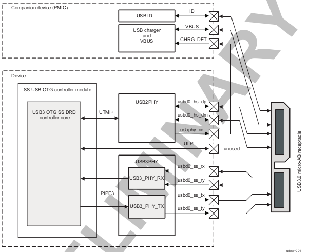
DRA7x/AM57x
The above diagram also depicts dwc3 integration in DRA7x/AM57x. Some boards provide VBUS and ID events over GPIO whereas some provide ID over GPIO and VBUS through Power Management IC (palmas).
- DRA7-evm (J6-evm) and DRA72-evm (J6-eco) boards have ID detection but no VBUS detection support. ID detection is provided through GPIO expander (PCF8574).
- DRA71-evm (J6entry-evm) board has VBUS and ID detection support. Both ID and VBUS detection are provided through GPIO expander (PCF8574).
On these boards, the GPIO driver (drivers/extcon/extcon-usb-gpio.c) notifies the ID and VBUS events to the OMAP dwc3 glue (drivers/usb/dwc3/dwc3-omap.c) via the extcon framework.
All DRA7x boards use USB1 port as Super-Speed dual-role port and USB2 port High-Speed Host port (Type mini-A). You will need a mini-A to Type-A adapter to use the Host port.
AM57x (BeagleBoard-x15/AM57xx-evm/AM57xx-IDK)
- BeagleBoard-x15/AM57xx-evm use USB1 as Super-Speed host port and have a on-board Super-Speed hub which provides 3 Super-Speed Host (Type-A) ports. USB2 is used as High-Speed peripheral port. VBUS detection for USB2 port is provided through Power Management IC (palmas). The palmas USB driver (drivers/extcon/extcon-palmas.c) notifies the VBUS event to the OMAP dwc3 glue (drivers/usb/dwc3/dwc3-omap.c) via the extcon framework.
- AM57xx-IDK boards use USB1 as a High-Speed Host port (Type-A) and USB2 as a High-Speed dual-role port. ID detection for USB2 is provided via GPIO whereas VBUS detection is provided through the PMIC (palmas). The palmas USB driver (drivers/extcon/extcon-palmas.c) notifies both VBUS and ID events to the OMAP dwc3 glue (drivers/usb/dwc3/dwc3-omap.c) via the extcon framework.
AM437x
The following diagram depicts dwc3 integration in AM437x. Super-Speed is not supported so maximum speed is high-speed. VBUS and ID detection is done by the internal PHY, so companion device is not needed. DWC3 controller uses HW UTMI mode to get the VBUS and ID events and the glue driver (omap-dwc3.c) does not need to write to the software mailbox to notify the events to the dwc3 core.
- On AM437x-gp-evm, AM437x-epos-evm and AM437x-sk-evm, USB0 port is used as dual-role port and USB1 port is used as Host port (Type-A).
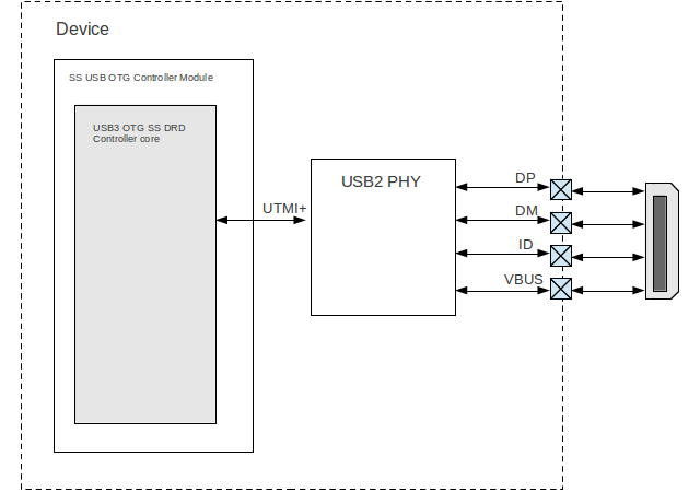
Features NOT supported
- Full OTG is not supported. Only dual-role mode is supported.
Driver Configuration
The default kernel configuration enables support for USB_DWC3, USB_DWC3_OMAP (the wrapper driver), USB_DWC3_DUAL_ROLE.
The selection of DWC3 driver can be modified as follows: start Linux Kernel Configuration tool.
$ make menuconfig ARCH=arm
- Select Device Drivers from the main menu.
...
...
Kernel Features --->
Boot options --->
CPU Power Management --->
Floating point emulation --->
Userspace binary formats --->
Power management options --->
[*] Networking support --->
Device Drivers --->
...
...
Building into Kernel
- Select USB support from the menu.
...
Multimedia support --->
Graphics support --->
<M> Sound card support --->
HID support --->
[*] USB support --->
< > Ultra Wideband devices ----
<*> MMC/SD/SDIO card support --->
...
- Enable Host-side support and Gadget support
...
<M> Support for Host-side USB
...
<M> USB Gadget Support
...
- Select DesignWare USB3 DRD Core Support and Texas Instruments OMAP5 and similar Platforms
...
<M> DesignWare USB3 DRD Core Support
DWC3 Mode Selection (Dual Role mode) --->
*** Platform Glue Driver Support ***
<M> Texas Instruments OMAP5 and similar Platforms
...
- Select Bus devices OMAP2SCP driver
...
-*- OMAP INTERCONNECT DRIVER
<*> OMAP OCP2SCP DRIVER
...
- Select the PHY Subsystem for OMAP5, DRA7x and AM437x
...
[*] Reset Controller Support --->
< > FMC support ---->
PHY Subsystem --->
...
- Select the OMAP CONTRO PHY driver, OMAP USB2 PHY driver for OMAP5, DRA7 and AM437x
- Select OMAP PIPE3 PHY driver for OMAP5 and DRA7x
...
-*- PHY Core
-*- OMAP CONTROL PHY Driver
<*> OMAP USB2 PHY Driver
<*> TI PIPE3 PHY Driver
...
- Select ‘xHCI HCD (USB 3.0) SUPPORT’ from menuconfig in ‘USB support’
< > Support WUSB Cable Based Association (CBA)
*** USB Host Controller Drivers ***
...
<*> xHCI HCD (USB 3.0) support
...
- Select ‘USB Gadget Support —>’ from menuconfig in ‘USB support’ and select the needed gadgets. (By default all gadgets are made as modules)
--- USB Gadget Support
[*] Debugging messages (DEVELOPMENT)
[ ] Verbose debugging Messages (DEVELOPMENT)
[*] Debugging information files (DEVELOPMENT)
[*] Debugging information files in debugfs (DEVELOPMENT)
(2) Maximum VBUS Power usage (2-500 mA)
(2) Number of storage pipeline buffers
USB Peripheral Controller --->
<M> USB Gadget Drivers
< > USB functions configurable through configfs
<M> Gadget Zero (DEVELOPMENT)
<M> Audio Gadget
[ ] UAC 1.0 (Legacy)
<M> Ethernet Gadget (with CDC Ethernet support)
[*] RNDIS support
[ ] Ethernet Emulation Model (EEM) support
<M> Network Control Model (NCM) support
<M> Gadget Filesystem
<M> Function Filesystem
[*] Include configuration with CDC ECM (Ethernet)
[*] Include configuration with RNDIS (Ethernet)
[*] Include 'pure' configuration
<M> Mass Storage Gadget
<M> Serial Gadget (with CDC ACM and CDC OBEX support)
<M> MIDI Gadget
<M> Printer Gadget
<M> CDC Composite Device (Ethernet and ACM)
<M> CDC Composite Device (ACM and mass storage)
<M> Multifunction Composite Gadget
[*] RNDIS + CDC Serial + Storage configuration
[*] CDC Ethernet + CDC Serial + Storage configuration
<M> HID Gadget
<M> HID Gadget
<M> EHCI Debug Device Gadget
EHCI Debug Device mode (serial) --->
<M> USB Webcam Gadget
Configuring DWC3 in gadget only
set ‘dr_mode’ as ‘peripheral’ in respective board dts files present in arch/arm/boot/dts/
- omap5-uevm.dts for OMAP5
- dra7-evm.dts for DRA7x
- am4372.dtsi for AM437x
Example: To configure both the ports of DRA7 as gadget (default usb2 is configured as 'host')
arch/arm/boot/dts/dra7-evm.dts
&usb1 {
dr_mode = "peripheral";
pinctrl-names = "default";
pinctrl-0 = <&usb1_pins>;
};
&usb2 {
dr_mode = "peripheral";
pinctrl-names = "default";
pinctrl-0 = <&usb2_pins>;
};
Configuring DWC3 in host only
set ‘dr_mode’ as ‘host’ in respective board dts files present in arch/arm/boot/dts/
- omap5-uevm.dts for OMAP5
- dra7-evm.dts for DRA7x
- am4372.dtsi for AM437x
Example: To configure both the ports of DRA7 as host (default usb1 is configured as 'otg')
arch/arm/boot/dts/dra7-evm.dts
&usb1 {
dr_mode = "host";
pinctrl-names = "default";
pinctrl-0 = <&usb1_pins>;
};
&usb2 {
dr_mode = "host";
pinctrl-names = "default";
pinctrl-0 = <&usb2_pins>;
};
Testing
Host Mode
Selecting cables
OMAP5-uevm
OMAP5-evm has a single Super-Speed micro AB port provided by the DWC3 controller. To use it in host mode a OTG adapter (Micro USB 3.0 9-Pin Male to USB 3.0 Female OTG Cable) like below should be used. The ID pin within the adapter must be grounded. Some of the adapters available in the market don’t have ID pin grounded. If the ID pin is not grounded the dual-role port will not switch from peripheral mode to host mode.
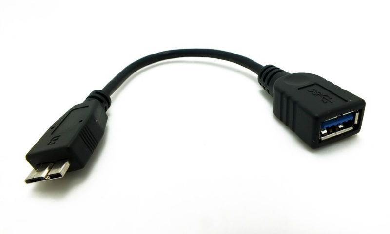
DRA7x-evm
DRA7x-evm has 2 USB ports provided by the DWC3 controllers. USB1 is a Super-Speed port and USB2 is a High-Speed port. USB1 is by default configured in dual-role mode and USB2 is configured in host mode.
For connecting a device to the USB2 port use a mini-A to Type-A OTG adapter cable like this. The ID pin within the adapter cable must be grounded.
For using the USB1 port in host mode use a Super-Speed OTG adapter cable similar to the one used in OMAP5.
AM437x
AM437x has two USB ports. USB0 is a host port and USB1 is a dual-role port.
The USB0 host port has a standard A female so no special cables needed. To use the USB1 port in host mode a micro OTG adapter cable is required like below.
Example
Connecting a USB2 pendrive to DRA7x gives the following prints
root@dra7xx-evm:~# [ 479.385084] usb 1-1: new high-speed USB device number 2 using xhci-hcd
[ 479.406841] usb 1-1: New USB device found, idVendor=054c, idProduct=05ba
[ 479.413911] usb 1-1: New USB device strings: Mfr=1, Product=2, SerialNumber=3
[ 479.422320] usb 1-1: Product: Storage Media
[ 479.426901] usb 1-1: Manufacturer: Sony
[ 479.430949] usb 1-1: SerialNumber: CB5001212140006303
[ 479.437774] usb 1-1: ep 0x81 - rounding interval to 128 microframes, ep desc says 255 microframes
[ 479.447454] usb 1-1: ep 0x2 - rounding interval to 128 microframes, ep desc says 255 microframes
[ 479.458124] usb-storage 1-1:1.0: USB Mass Storage device detected
[ 479.465355] scsi1 : usb-storage 1-1:1.0
[ 480.784475] scsi 1:0:0:0: Direct-Access Sony Storage Media 0100 PQ: 0 ANSI: 4
[ 480.801677] sd 1:0:0:0: [sda] 61046784 512-byte logical blocks: (31.2 GB/29.1 GiB)
[ 480.820740] sd 1:0:0:0: [sda] Write Protect is off
[ 480.825794] sd 1:0:0:0: [sda] Mode Sense: 43 00 00 00
[ 480.832797] sd 1:0:0:0: [sda] No Caching mode page found
[ 480.838574] sd 1:0:0:0: [sda] Assuming drive cache: write through
[ 480.852070] sd 1:0:0:0: [sda] No Caching mode page found
[ 480.857672] sd 1:0:0:0: [sda] Assuming drive cache: write through
[ 480.865873] sda: sda1
[ 480.874068] sd 1:0:0:0: [sda] No Caching mode page found
[ 480.879839] sd 1:0:0:0: [sda] Assuming drive cache: write through
[ 480.886434] sd 1:0:0:0: [sda] Attached SCSI removable disk
Device Mode
Mass Storage Gadget
In gadget mode standard USB cables with micro plug should be used.
Example: To use ramdisk as a backing store use the following
# mkdir /mnt/ramdrive
# mount -t tmpfs tmpfs /mnt/ramdrive -o size=600M
# dd if=/dev/zero of=/mnt/ramdrive/vfat-file bs=1M count=600
# mkfs.ext2 -F /mnt/ramdrive/vfat-file
# modprobe g_mass_storage file=/mnt/ramdrive/vfat-file
In order to see all other options supported by g_mass_storage, just run modinfo command:
# modinfo g_mass_storage
filename: /lib/modules/3.17.0-rc6-00455-g0255b03-dirty/kernel/drivers/usb/gadget/legacy/g_mass_stor
age.ko
license: GPL
author: Michal Nazarewicz
description: Mass Storage Gadget
srcversion: 3050477C3FFA3395C8D79CD
depends: usb_f_mass_storage,libcomposite
intree: Y
vermagic: 3.17.0-rc6-00455-g0255b03-dirty SMP mod_unload modversions ARMv6 p2v8
parm: idVendor:USB Vendor ID (ushort)
parm: idProduct:USB Product ID (ushort)
parm: bcdDevice:USB Device version (BCD) (ushort)
parm: iSerialNumber:SerialNumber string (charp)
parm: iManufacturer:USB Manufacturer string (charp)
parm: iProduct:USB Product string (charp)
parm: file:names of backing files or devices (array of charp)
parm: ro:true to force read-only (array of bool)
parm: removable:true to simulate removable media (array of bool)
parm: cdrom:true to simulate CD-ROM instead of disk (array of bool)
parm: nofua:true to ignore SCSI WRITE(10,12) FUA bit (array of bool)
parm: luns:number of LUNs (uint)
parm: stall:false to prevent bulk stalls (bool)
Note: The USB Mass Storage Specification requires us to pass a valid iSerialNumber of 12 alphanumeric digits, however g_mass_storage will not generate one because the Kernel has no way of generating a stable and valid Serial Number. If you want to pass USB20CV and USB30CV MSC tests, pass a valid iSerialNumber argument.
USB 2.0 Test Modes
The Universal Serial Bus 2.0 Specification defines a set of Test Modes used to validate electrical quality of Data Lines pair (D+/D-). There are two ways of entering these Test Modes with DWC3.
- Sending properly formatted SetFeature(TEST) Requests to the device (see USB2.0 spec for details)
This is the preferred (and Standard) way of entering USB 2.0 Test Modes. However, it’s not always that we will have a functioning USB Host to issue such requests.
- Using a non-standard DebugFS interface (see below for details)
Any time we don’t have a functioning Host on the Test Setup and still want to enter USB 2.0 Test Modes, we can use this non-standard interface for that purpose. One such use-case is for low level USB 2.0 Eye Diagram testing where the DUT (Device Under Test) is connected to an oscilloscope through a test fixture.
Non-Standard DebugFS Interface
DWC3 Driver exposes a few testing and development tools through the Debug File System. In order to use it, you must first mount that file system in case it’s not mounted yet. Below, we show an example session on AM437x.
# mount -t debugfs none /sys/kernel/debug
# cd /sys/kernel/debug
# ls
48390000.usb dri memblock regulator ubifs
483d0000.usb extfrag mmc0 sched_features usb
asoc fault_around_bytes omap_mux sleep_time wakeup_sources
bdi gpio pinctrl suspend_stats
clk hid pm_debug tracing
dma_buf kprobes regmap ubi
Note the two directories terminated with .usb. Those are the two instances available on AM437x devices, 48390000.usb is USB1 and 483d0000.usb is USB2. Both of those directories contain the same thing, we will use 48390000.usb for the purposes of illustration.
# cd 48390000.usb
# ls
link_state mode regdump testmode
link_state
Shows the current USB Link State
# cat link_state
U0
mode
Shows the current mode of operation. Available options are host, device, otg. It can also be used to dynamically change the mode by writing to this file any of the available options. Dynamically changing the mode of operation can be useful for debug purposes but this should never be used in production.
# cat mode
device
# echo host > mode
# cat mode
host
# echo device > mode
# cat mode
device
regdump
Shows a dump of all registers of DWC3 except for XHCI registers which are owned by the xhci-hcd driver.
# cat regdump
GSBUSCFG0 = 0x0000000e
GSBUSCFG1 = 0x00000f00
GTXTHRCFG = 0x00000000
GRXTHRCFG = 0x00000000
GCTL = 0x25802004
GEVTEN = 0x00000000
GSTS = 0x3e800002
GSNPSID = 0x5533240a
GGPIO = 0x00000000
GUID = 0x00031100
GUCTL = 0x02008010
GBUSERRADDR0 = 0x00000000
GBUSERRADDR1 = 0x00000000
GPRTBIMAP0 = 0x00000000
GPRTBIMAP1 = 0x00000000
GHWPARAMS0 = 0x402040ca
GHWPARAMS1 = 0x81e2493b
GHWPARAMS2 = 0x00000000
GHWPARAMS3 = 0x10420085
GHWPARAMS4 = 0x48a22004
GHWPARAMS5 = 0x04202088
GHWPARAMS6 = 0x08800c20
GHWPARAMS7 = 0x03401700
GDBGFIFOSPACE = 0x00420000
GDBGLTSSM = 0x01090460
GPRTBIMAP_HS0 = 0x00000000
GPRTBIMAP_HS1 = 0x00000000
GPRTBIMAP_FS0 = 0x00000000
GPRTBIMAP_FS1 = 0x00000000
GUSB2PHYCFG(0) = 0x00002500
GUSB2PHYCFG(1) = 0x00000000
GUSB2PHYCFG(2) = 0x00000000
GUSB2PHYCFG(3) = 0x00000000
GUSB2PHYCFG(4) = 0x00000000
GUSB2PHYCFG(5) = 0x00000000
GUSB2PHYCFG(6) = 0x00000000
GUSB2PHYCFG(7) = 0x00000000
GUSB2PHYCFG(8) = 0x00000000
GUSB2PHYCFG(9) = 0x00000000
GUSB2PHYCFG(10) = 0x00000000
GUSB2PHYCFG(11) = 0x00000000
GUSB2PHYCFG(12) = 0x00000000
GUSB2PHYCFG(13) = 0x00000000
GUSB2PHYCFG(14) = 0x00000000
GUSB2PHYCFG(15) = 0x00000000
GUSB2I2CCTL(0) = 0x00000000
GUSB2I2CCTL(1) = 0x00000000
GUSB2I2CCTL(2) = 0x00000000
GUSB2I2CCTL(3) = 0x00000000
GUSB2I2CCTL(4) = 0x00000000
GUSB2I2CCTL(5) = 0x00000000
GUSB2I2CCTL(6) = 0x00000000
GUSB2I2CCTL(7) = 0x00000000
GUSB2I2CCTL(8) = 0x00000000
GUSB2I2CCTL(9) = 0x00000000
GUSB2I2CCTL(10) = 0x00000000
...
A better use for this is, if you know the register name you’re looking for, by using grep we can reduce the amount of output. Assuming we want to check register DCTL we could:
# grep DCTL regdump
DCTL = 0x8c000000
testmode
Shows current USB 2.0 Test Mode. Can also be used to enter such test modes in situations where we can’t issue proper SetFeature(TEST) requests. Available options are test_j, test_k, test_se0_nak, test_packet, test_force_enable. The only way to exit the test modes is through a USB Reset.
# cat testmode
no test
# echo test_packet > testmode
# cat testmode
test_packet
Other Resources
For general Linux USB subsystem - Usbgeneralpage
USB Debugging - elinux.org/images/1/17/USB_Debugging_and_Profiling_Techniques.pdf
3.3.4.28. VPE
Introduction
- This page gives a basic description of VPE mem to mem video IP found in devices, the linux kernel drivers which implement it, how to build the drivers as modules or built-in, and how one can test and use the drivers.
- The driver described here is the VPE v4l2 mem-2-mem driver.
- The guide applies to both 3.12 and the current mainline kernel. Currently, DRA7x requires additional patches for hwmod and DT support for mainline.
- For a generic linux kernel guide, try:
http://processors.wiki.ti.com/index.php/Linux_Kernel_Users_Guide
VPE Supported Devices
DRA7x evm, AM57xx evm
Driver Features
Video processing Engine(VPE) supports following formats for scaling, csc and deinterlacing:
- Supported Input formats: NV12, YUYV, UYVY
- Supported Output formats: NV12, YUYV, UYVY, RGB24, BGR24, ARGB24, ABGR24
- Scaler supports
- Horizontal up-scaling up to 8x and Downscaling up to 4x using Pre-decimation filter.
- Vertical up-scaling up to 8x and Polyphase down-scaling up to 4x followed by RAV scaling.
- V4L2 Multiplanar ioctl() supported.
- Multiple V4L2 device context supported.
- v4l2 m2m related ioctls.
Changes from 3.12 to 3.15
- Changes in 3.13:
- Basic VPE driver introduced with DEI support.
- Changes in 3.14:
- Support added for scaler and color space converter.
- Changes in 3.15:
- Misc fixes found during testing.
Unsupported Features/Limitations
- Following formats are not supported : YUV444, YVYU, VYUY, NV16, NV61, NV21, 16bit and Lower RGB formats are not supported.
- Passing of custom scaler and CSC coeffficients through user space are not supported.
- Only Linear scaling is supported without peaking and trimming.
- Deinterlacer does not support film mode detection.
- VPE functional clock is restricted to 152Mhz due to HW constraints.
Hardware Architecture
VPE(Video Processing Engine) is an IP found on DRA7xx, and in some past TI multimedia SoCs which don’t have baseport support in the mainline kernel.
VPE is a memory to memory block used for performing de-interlacing, scaling and color conversion on input buffers. It’s primarily used to de-interlace decoded DVD/Blu Ray video buffers, and provide the content to progressive display or do some other post processing. VPE can also be used for other tasks like fast color space conversion, scaling and chrominance up/down sampling. The scaler in particular is based on a polyphase filter and supports 32 phases and 5/7 taps.
VPE’s De-interlacer IP: The De-interlacer module performs a combination of spatial and temporal interlacing, it determines the weight-age by keeping a track of the change in motion between fields by maintaining and updating a motion vector buffer in the RAM. The de-interlacer needs the current field and the 2 previous fields (along with the motion vector info)to generate a progressive frame. It operates on YUV422 data.
VPDMA: All the DMAs are done through a dedicated DMA IP called VPDMA(Video Port Direct Memory Access). This DMA IP is specialized for transferring video buffers, the input and output data ports of VPDMA are configured via descriptor lists loaded to the VPDMA list manager. VPDMA is also used to load MMRs of the various VPE sub blocks.
VPDMA is advanced enough to support multiple clients like a system DMA, however, the way it’s integrated in the SoC is such that it can be used only by the VPE IP. The same IP is also used on DRA7x in another block called VIP (full form) used to capture camera sensor content. It’s again dedicated to the VIP block, and therefore doesn’t have multiple clients. These factors made us consider writing the VPDMA block as a library, providing functions to VPE(and VIP in the future) to add descriptors and start DMA. It might have made sense to make it a dmaengine driver if there were multiple clients using VPDMA.
f, f - 1, and f - 2 are input ports fetching 3 consecutive fields for the de-interlacer. MVin and MVout are ports which fetch the current motion vector and output the updated motion vector respectively. There are 2 output ports, one for YUV output and the other for RGB output if the color space converter(CSC) is used. The inputs can be YUV packed or semiplanar formats. The chrominance upsampler(CHR_USx) is used when the input format is NV12, the chrominance downsampler(CHR_DS) is used if the the output content needs to be NV12 format. The scaler(SC) can be used to scale the de-interlaced content if needed.
For a diagram, look here:
http://www.spinics.net/lists/linux-media/msg66518.html
Driver Architecture
The VPE driver follows the standard v4l2 mem 2 mem model. An introduction can be found here:
https://lwn.net/Articles/389081/
Each mem 2 mem context holds a hardware state of VPE, and the software state of the VPE device. One context can be paused, and another context can be initiated with it’s own VPE state. In this way, the driver supports multiple open() calls, allowing multiple applications to share VPE cycles.
Driver Configuration
Source Location
- kernel driver:
drivers/media/platform/ti-vpe/
Kernel Configuration Options
Kernel config(built-in)
- Start with the default config:
$ make ARCH=arm omap2plus_defconfig
- Select the following things after a menuconfig:
$ make ARCH=arm menuconfig
- Go to the Device drivers option:
...
...
Kernel Features --->
Boot options --->
CPU Power Management --->
Floating point emulation --->
Userspace binary formats --->
Power management options --->
[*] Networking support --->
Device Drivers --->
...
...
- Select Multimedia support as a module, and go inside:
...
...
[ ] ARM Versatile Express platform infrastructure
-*- Voltage and Current Regulator Support --->
<M> Multimedia support --->
Graphics support --->
<M> Sound card support --->
...
...
- Select Cameras/video grabbers support, Memory-to-memory multimedia devices(as a module), and enter the latter:
--- Multimedia support
*** Multimedia core support ***
[*] Cameras/video grabbers support
[ ] Analog TV support
[ ] Digital TV support
...
...
[M] Memory-to-memory multimedia devices --->
...
...
- Select the VPE mem2mem driver:
--- Memory-to-memory multimedia devices
< > Deinterlace support (NEW)
< > SuperH VEU mem2mem video processing driver (NEW)
<M> TI VPE (Video Processing Engine) driver
[ ] VPE debug messages (NEW)
- Build the kernel image and the modules, ahoy:
make uImage
make modules
- User space will require an ioctl base in v4l2-controls.h, so make sure you update the headers:
make headers-install
Kernel config(modules)
Similar to built-in, just replace with <M>.
Driver Usage
Loading Modules
The kernel config above builds vpe as a kernel module(ti-vpe.ko). There are some dependencies which need to be taken care of. The v4l and videobuf modules are:
insmod videodev.ko
insmod videobuf2-core.ko
insmod videobuf2-memops.ko
insmod videobuf2-dma-contig.ko
insmod v4l2-common.ko
insmod v4l2-mem2mem.ko
And finally:
insmod ti-vpe.ko
Loading firmware
The VPDMA block within VPE requires firmware to be loaded from userspace. The firmware along with the testcase is put here:
git://git.ti.com/vpe_tests/vpe_tests.git
Build the test case
make install
This builds the test case, and copies it into $(DESTDIR)/usr/bin, and the firmware into $(DESTDIR)/lib/firmware.
The firmware file name is ‘vpdma-1b8.bin’. There are 2 ways to load the firmware:
- Place the firmware in the ‘lib/firmware/’ folder of your filesystem.
- The manual method:
$ echo 6000 > /sys/class/firmware/timeout
$ echo 1 > /sys/class/firmware/vpdma-1b8.bin/loading
$ cat vpdma-1b8.bin > /sys/class/firmware/vpdma-1b8.bin/data
$ echo 0 > /sys/class/firmware/vpdma-1b8.bin/loading
Testing the driver
Use the git repository above to try out this low level test case.
The usage is something like this:
$ ./testvpem2m <src-file> <src-width> <src-height> <src-format>
<dst-file> <dst-width> <dst-height> <dst-format> [<crop-top> <crop-left>
<crop-width> <crop-height>] <de-interlace> <job-len>
Some points about the arguments:
- We just support de-interlacing of the source frames for now.
- If <de-interlace> is set to 1, the testcase tries to perform de-interlacing, irrespective of what the content is.
- If <de-interlace> is set to 0, the DEI block is bypassed. You can still use it for scaler and color conversion.
- Only interlaced content in the form of top-bottom fields are supported.
- When testing higher resolutions, make sure we increase the CMA memory through the ‘cma’ bootarg.
- <job-len> tells how many times you want your test app to use the VPE hardware. In real use cases, this should be decided based upon various factors like QoS, video resolution, and so on.
- We can run multiple instances of this test, and each one will get a slice of VPE based on the <job-len> provided for each instance.
An example of de-interlacing a 480i nv12 clip to a 480p yuyv clip:
$ ./testvpem2m 480i_clip.nv12 720 240 nv12 dei_480p_clip.yuv 720 480 yuyv 1 3
An example of just scaling/colorspace-converting a progressive 640x480 nv12 clip to a smaller resolution rgb clip:
$ ./testvpem2m 640_480p.nv12 640 480 nv12 360_240p.rgb24 360 240 rgb24 0 3
The <dst-file> should contain the VPE output content.
This is a standalone VPE test case. In real usage, VPE won’t allocate buffers by itself. It will use dma-bufs shared by a dmabuf exporter(most likely omapdrm) instead of allocating by itself via the videobuf2 layer.
Debugging
Debug log can be enabled in the VPE driver by adding “#define DEBUG” at the first line of drivers/media/platform/ti-vpe/vpe.c.
3.3.5. LTP-DDT Validation
Document License
This work is licensed under the Creative Commons Attribution-Share Alike 3.0 United States License. To view a copy of this license, visit https://creativecommons.org/licenses/by-sa/3.0/us/ or send a letter to Creative Commons, 171 Second Street, Suite 300, San Francisco, California, 94105, USA.
LTP-DDT Overview
LTP-DDT is a test application used by Texas Instruments to validate Linux releases.
LTP-DDT uses LTP’s test infrastructure, such as:
- Test execution drivers (PAN)
- Top-level test scripts (i.e. runltp)
- Same Folder Hierarchy and test case definition format
LTP-DDT test cases are LTP test cases and vice-versa.
The main additions or ‘enhacements’ of LTP-DDT compared to LTP are:
- PLATFORM files. LTP-DDT uses PLATFORM files to identify platform hardware and software features.
- OVERRIDE mechanism. Default test case parameters are automatically overridden based on PLATFORM features.
- ATOMIC scripts. Code reuse is foster by writing scripts that implement small well-defined actions. Test scripts rely on these atomic scripts to execute their actions.
- AUTOMATIC FILTERING. Test cases are filtered based on the test requirements and the PLATFORM features.
- TESTCASE ANNOTATIONS. Test scenario files are annotated with following annotations @name, @desc, @requires and @setup_requires. The @requires and @setup_requires are used to select test cases at run time based on the PLATFORM features.
- All LTP-DDT test cases and test code reside in <testcases-root>/ddt/ and <testcode-root>/ddt/ folders respectively.
LTP-DDT Highlights
- Easy to use (automatically filter test cases not applicable for platform)
- Easy to support new platforms (just define the platform file)
- Test cases can be easily wrap or imported to Test Management Systems (Use of testcase annotations facilitates this)
- High Code Reuse (atomic scripts and test scripts are reused and parameters are adjusted on the fly)
Test Suites
- alsa
- cpu hotplug
- crypto
- timers
- emmc
- mmc/sd
- ethernet
- fbdev
- gpio
- gstreamer (multimedia)
- hdmi
- i2c
- ipc
- latency under different use cases (important for RT kernel)
- lmbench
- memory tests
- mm (ltp’s memory management)
- msata
- nand
- nor
- pci
- pipes (ltp)
- power management
- programmable real-time unit (PRU)
- pwm
- qspi
- realtime (ltp)
- rng
- rtc
- sata
- scheduler (ltp)
- sgx (graphics)
- smp
- spi
- syscalls (ltp)
- system (use-cases, e.g. multiple tests running in parallel)
- thermal
- timers (ltp)
- touchscreen
- uart
- usb host (multiple tests with different classes)
- usb device
- v4l2
- vlan
- dwt
- wlan
Device Under Tests Supported
LTP-DDT has been used on following devices:
am170x-evm am335x-ice am389x-evm am43xx-hsevm beagleboard dm365-evm dra71x-evm dra7xx-hsevm k2g-evm omap3evm ti811x-evm
am180x-evm am335x-sk am437x-idk am571x-idk beaglebone dm368-evm dra71x-hsevm dragonboard410c k2g-ice omap5-evm ti813x-evm
am181x-evm am3517-evm am437x-sk am572x-idk beaglebone-black dm385-evm dra72x-evm hikey k2hk-evm omapl138-lcdk
am335x-evm am37x-evm am43xx-epos am57xx-evm da830-omapl137-evm dm6467-evm dra72x-hsevm k2e-evm k2l-evm tci6614-evm
am335x-hsevm am387x-evm am43xx-gpevm am57xx-hsevm da850-omapl138-evm dm813x-evm dra7xx-evm k2e-hsevm
Host Platform Requirements
Linux host is required :
- for compiling LTP-DDT.
- to host the NFS server to boot the EVM with NFS as root filesystem
- to run host utilities - e.g.iperf
Host Software Requirements
- GCC Tool chain for ARM
- Serial console terminal application
- TFTP and NFS servers. NFS server is required only in case of NFS boot.
- iperf utility on the host.
Filesystem Requirements
LTP-DDT relies on other open source test tools. The following test tools must be available in the target filesystem to run ltp-ddt:
- alsa utilities
- evtest
- hdparm
- iperf
- lmbench
- rt-tests (cyclictest)
There is an Arago/OE recipe here that builds a filesystem image w/ the above tools plus:
- bonnie++
- iozone3
- ltp-ddt
Installation
Clone the project
git clone http://arago-project.org/git/projects/test-automation/ltp-ddt.git
Running Tests
- Run DDT tests the same way you run LTP tests. Use ltprun program and pass to
it the test scenario file in the runtest directory (option -f) to run and the platform (option -P) to use. For example:
./runltp -P am180x-evm -f ddt/lmbench
- In addition to selecting test scenarios using -f option, users can also
- The runltp script have lot of options. Some useful ones for stress tests are:
-t DURATION: Define duration of the test in s,m,h,d.
-x INSTANCES: Run multiple test instances in parallel.
-c <options>: Run test under additional background CPU load
-D <options>: Run test under additional background load on Secondary storage
-m <options>: Run test under additional background load on Main memory
-i <options>: Run test under additional background load on IO Bus
-n : Run test with network traffic in background.
Please refer to README-DDT file section 8) for more details.
- Running NAND Sanity Tests
– Run all NAND sanity tests
Using below command to run NAND sanity tests.
./runltp -P <platform> -s "NAND_S_" -S skiplist
If there are more than one flash filesystem supported, say, jffs2 and ubifs and you don’t run jffs2 test cases. You need create a file called ‘skiplist’ (this filename could be anything) and put to-be-skipped test case tag in this file. Here is the content of skiplist to skip jffs2 test cases.
@ cat skiplist
_JFFS2
– Run NAND performance test
./runltp -P <platform> -s "NAND_L_PERF" -S skiplist
Join
3.3.6. FAQs
Q: Howto let Linux not load kernel modules automatically during system boot time?
# cat /etc/modprobe.d/modprobe.conf
blacklist musb_am335x
Q: Howto disable a peripheral then enable it again?
root@dra7xx-evm:~# find /sys -name unbind | grep rtc
/sys/bus/platform/drivers/omap_rtc/unbind
root@dra7xx-evm:~# cd /sys/bus/platform/drivers/omap_rtc/
root@dra7xx-evm:/sys/bus/platform/drivers/omap_rtc# ls
48838000.rtc bind module uevent unbind
root@dra7xx-evm:/sys/bus/platform/drivers/omap_rtc# echo 48838000.rtc > unbind
root@dra7xx-evm:/sys/bus/platform/drivers/omap_rtc#
to enable it again,
root@dra7xx-evm:/sys/bus/platform/drivers/omap_rtc# echo 48838000.rtc > bind
[ 7792.863975] omap_rtc 48838000.rtc: already running
[ 7792.869822] omap_rtc 48838000.rtc: rtc core: registered 48838000.rtc as rtc1
root@dra7xx-evm:/sys/bus/platform/drivers/omap_rtc#
3.4. Filesystem
Introduction
Filesystem Images
There are two filesystem images provided in the SDK. You’ll find them at the SDK Installation directory/filesystem folder.
arago-base-tisdk-image
tisdk-rootfs-image
This is the complete filesystem image, that contains standard Linux commands and features. This also contains the TI component libraries, binaries and out of box examples. For keystone devices (e.g., K2H/K2K, K2E, K2L, and K2G), two filesystem tarballs are provided due to size limit of the rootfs ubi image:
- tisdk-server-rootfs-image-k2g-evm.tar.gz: base filesystem image used to create the ubi image.
- tisdk-server-extra-rootfs-image-k2g-evm.tar.gz: complete filesystem image that can be used with NFS and/or SD card (K2G only).
3.5. Tools
There are many tools available to help with Linux development on TI platforms. From Code Composer Studio, an Eclipse IDE that can be used for debug and development, to scripts and production tools, you’ll find a variety of help on this page.
3.5.1. Development Tools
3.5.1.1. Processor SDK Linux Top-Level Makefile
Please refer to Top-Level Makefile for details.
3.5.1.2. Processor SDK Linux GCC Toolchain
Please refer to GCC ToolChain for details.
3.5.1.3. Creating SD Cards
Please refer to Linux SD Card Creation Guide for details.
3.5.1.4. Processor SDK Linux Setup Script
Please refer to Run Setup Scripts for details.
3.5.2. Flash Tools
3.5.2.1. Sitara Uniflash
Introduction
This document describes a process to program Flash memory (NAND, NOR, SPI, QSPI and eMMC) attached to a TI AM335x or AM437x processor on a production target board. This is possible using either the Ethernet interface or the USB device interface available on the AMxxxx SoC connected to a host PC. This document is intended to guide those that want to program the flash memory on new boards for production.
The overall process is broken into two parts:
- Developing the images to both be programmed and do the programming from the AM335x or AM437x SoC. This is usually done by the Linux developer responsible for creating the images. This process is documented here.
- Actually programming the images using Uniflash v3. This tool runs on a Windows PC and serves the images to the target board that is being programmed. This process is detailed below.
Overview
Uniflash is one part of an overall system that includes the Windows PC on which Uniflash runs, a target board including an AM335x/AM437x Sitara Processor and flash memory to be programmed, and a USB or Ethernet connection between the two. It is assumed that the flash on the target board is blank, or needs to be overwritten. Therefore, the target board has nothing that it can execute except the bootloader stored in the ROM on the AM335x/AM437x SoC. So, the ROM bootloader will use either USB or Ethernet to request files served by Uniflash on the Host PC and once transferred, executed on the target board. The below diagram should help.
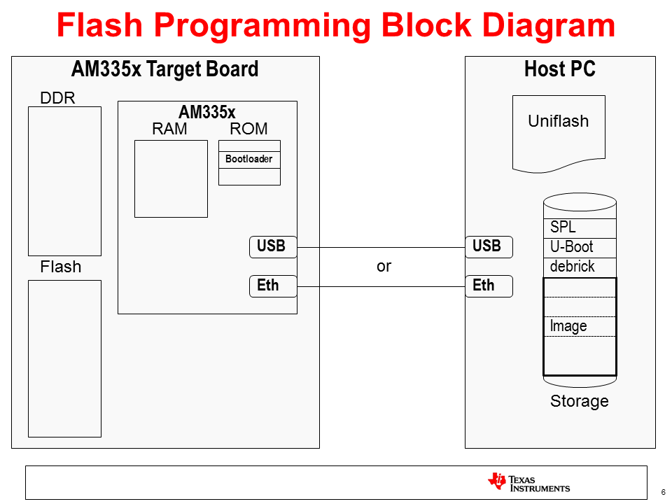
In the above diagram, take notice of the files stored on the PC. There are really 2 different images that will be used:
- The image to write the flash on the target board, which is composed of the SPL, U-Boot, and debrick or flasher files indicated. These will be pulled over by the bootloader in ROM when the target board is powered on (assuming the boot settings are set up to boot from USB or Ethernet).
- The image to be written. This is shown as “Image” and is pulled over from the Host PC. Once on the target, it will be broken up and written to the appropriate places in flash as determined by the flasher program above (mainly by the debrick or flasher script). This image will also likely contain a SPL and U-Boot, as well as a Kernel (zImage) and Root Filesystem. This is the image that will execute out of flash once it has been written and will vary depending the needs of the target board.
Using Uniflash to Program Flash Images
Once the images to be programmed into perpetual memory have been developed, an environment can be set up to program these images. This process involves a Client/Server type setup where a host PC serves as the server and the target board based on the AM335x/AM437x SoC serves as the client. The connection between the two can either be USB or Ethernet based. Since the USB protocol supported is Remote NDIS (or RNDIS hereafter), which is network (TCP/IP) based similar to Ethernet, both processes will be fairly similar.
In either configuration, the host PC provides the following services to the target through the Uniflash tool:
- BOOTP Server – to provide an IP address and image name based on the Vendor ID requested by the AM335x/AM437x ROM code
- DHCP Server – to provide an IP address to the target
- TFTP Server – to serve up images located on the host PC as they are requested by the target board
- GUI - friendly GUI environment for configuration and status
Host PC Setup
Here are some step by step instructions to configure a setup to flash target boards using a Windows PC. These steps were validated using Windows 7, however the steps should be similar for other versions of Windows.
Install Uniflash
Uniflash is a tool provided by Texas Instruments that supports multiple platforms and flash configurations. Support for Sitara devices was added in Uniflash version 3.0 and beyond.
- Download Uniflash v3 here.
- Extract the downloaded .zip archive to a temporary folder.
- Execute the Uniflash Setup program, uniflash_setup_3.3.0.00058.
- Click Next to accept the terms of the license agreement.
- Click Next to install into the default directory, c:\ti, or Browse to install somewhere else.
- Select Custom under type of Setup and click Next.
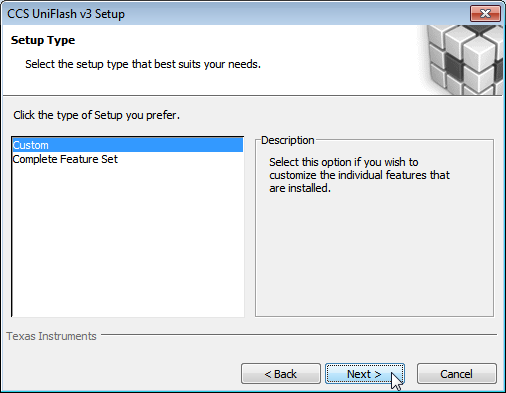
- Select Sitara AMxxxx processors and click Next.
- Verify that Sitara Flash Connection Support is checked.
- Click Next to verify your choices.
- Wait while Uniflash installs.
- Choose what options you’d like to have to start Uniflash (place on desktop, quick start, etc.)
- Uniflash is now installed and you should see something like this:

Preparing to Flash a Target Board
Now that Uniflash is installed, we need to make sure that it knows how to serve up the files needed to flash a target board. It needs to know where these files are located and how to send them to the target via either USB or Ethernet.
Here are the options for the Flash Servers Configuration that need to be properly set up:
- Network Interface IP - IP address that the Host Computer will use. Needs to correspond to the values used below to set up the Network Interface. The default value, 192.168.2.1, should be fine for most environments as it is a local IP Address.
- IP Lease - Amount of time an IP Address given to a target board is held for.
- DHCP IP Range Low - Low IP address in a range that will be given to a target board. Must be on the same subnet as the Network Interface IP of the Host Computer.
- DHCP IP Range High - High IP address in a range that will be given to a target board. Must be on the same subnet as the Network Interface IP of the Host Computer.
- TFTP Server IP - Should be the same as the Network Interface IP of the Host Computer.
- TFTP home folder - Folder on the host computer where the files to be served to the target board are located.
- Control Port - Socket used to allow the GUI to interact with servers. Should not be changed.
Given these definitions, set the values in Uniflash to match your environment. Note: that in most instances the default values should be fine and are recommended.
You must place the files to be served by the host PC to the target board in the TFTP home folder directory above. In most cases, you should have been given the below files to serve to the target board by the linux development team (these files can vary and are just an example):
- MLO or SPL
- A U-boot image
- A kernel image (if using a Linux kernel for flashing) and associated Device Tree file
- debrick.scr or flasher.sh
- Flash Image files (contains the images to be flashed on the target board)
AM437x Additional Setup
If you are using an AM437x device you the target board to be flashed, there are a couple of extra steps in order to pair Uniflash with the AM437x ROM code.
- After installing Uniflash, open the opendhcp.cfg file under the install directory, in the third_party\sitara folder using a text editor like Notepad.
- Add the two lines below to the [VENDOR_ID_TO_BOOTFILE_MAP]
section toward the top of the file:
- AM43xx ROM=u-boot-spl-restore.bin
- AM43xx U-B=u-boot-restore.img
Note:The 10 characters before the “=” must be exact as this is what is sent from the ROM code to request the next file in the flash procedure. The “x’s” in the AM43xx part are lower-case.
Flashing a Board using Ethernet
To program a board using the Ethernet interface between the Host PC and the target board, a private network between the two will be established. The HOST PC is set up with a Static IP address on one NIC (Network Interface Card) and connected to an ethernet switch or directly to the target board. A router that assigns IP addresses should not be used as the host PC needs to provide this to boot the target board.
Here is what you will need:
- Host PC with Uniflash installed and an available ethernet port.
- The files used to program the board put in the TFTP home folder set up in Uniflash.
- 2 ethernet cables if using a switch and one if using a direct connection.
- Ethernet switch (optional). Note: This should not be a router, as the host PC needs to provide IP addresses.
- Target board(s) to be programmed.
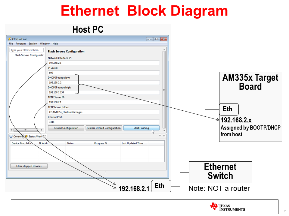
- If Uniflash is not already running on the Host PC, start it.
- Click on New Target Configuration.
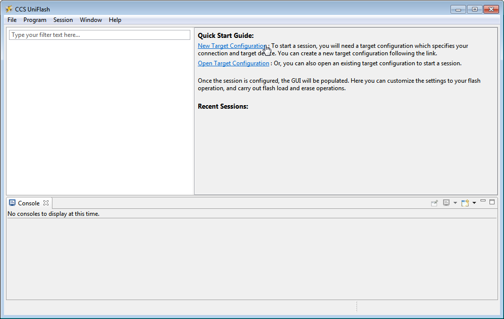
- Set Connection to Sitara Flash Connections and Board or Device to Sitara Flash Devices. Click OK.
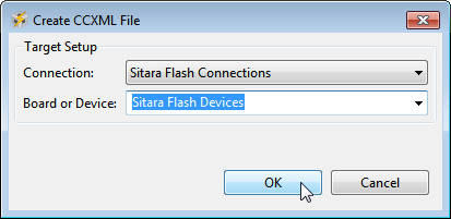
- Make sure the Flash Server Configuration is set up properly.
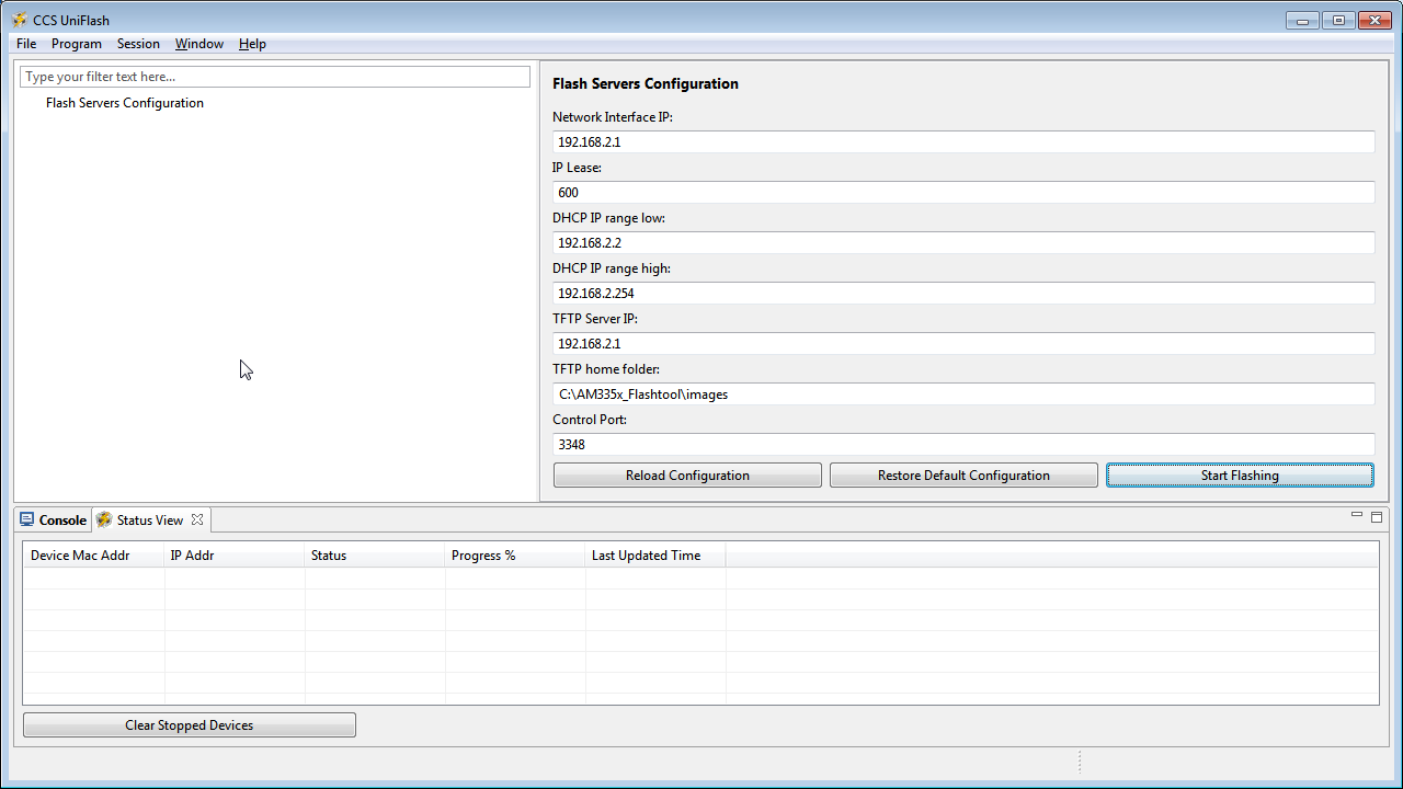
- Connect the Host PC to the network switch (or directly to the target board if using a direct connection).
- Click on the Open Network and Sharing Center.
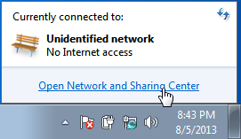
- Click on the Local Area Connection that corresponds to the ethernet connection. If you only have one, it should be the only one listed.
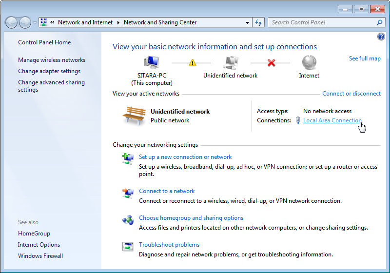
- In the Connection Dialog, Click on Properties.
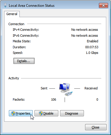
- Select Internet Protocol Version 4 (TCP/IPv4) and choose Properties.

- Set the port to use a Static IP Address by selecting Use the following IP Address: and changing the IP Address: to 192.168.2.1. This setting should correspond to the Network Interface IP setting in Uniflash.
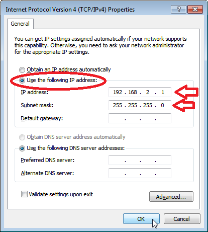
- Verify that the Subnet Mask is set to 255.255.255.0 and click OK.
- Click Close.
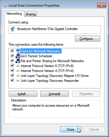
- Click Close one more time to get back to the Network Manager.
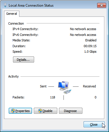
- Close Network Manager if you’d like as it should no longer be needed. The network is now set up.
- In Uniflash, enable the flashing capability by clicking on Start Flashing.
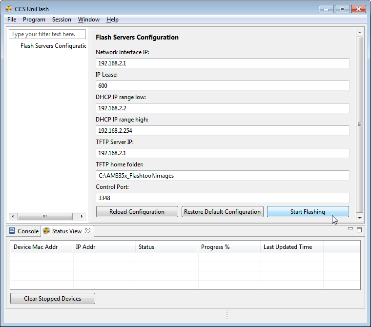
- Depending on your Windows Firewall settings, you may get the below two warnings for the servers being used (opendhcp and opentftp). If so, please click Allow access for both.

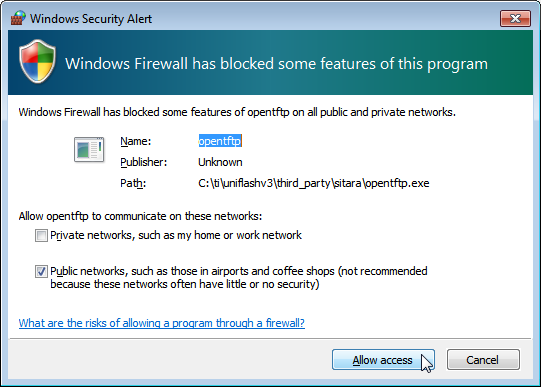
- Make sure the target board is powered and connect it via ethernet to the network switch (or directly).
- If everything is working correctly, the flashing process should start automatically on the board. You should see status feedback appear in Uniflash as the process progresses.
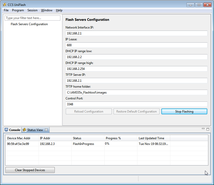
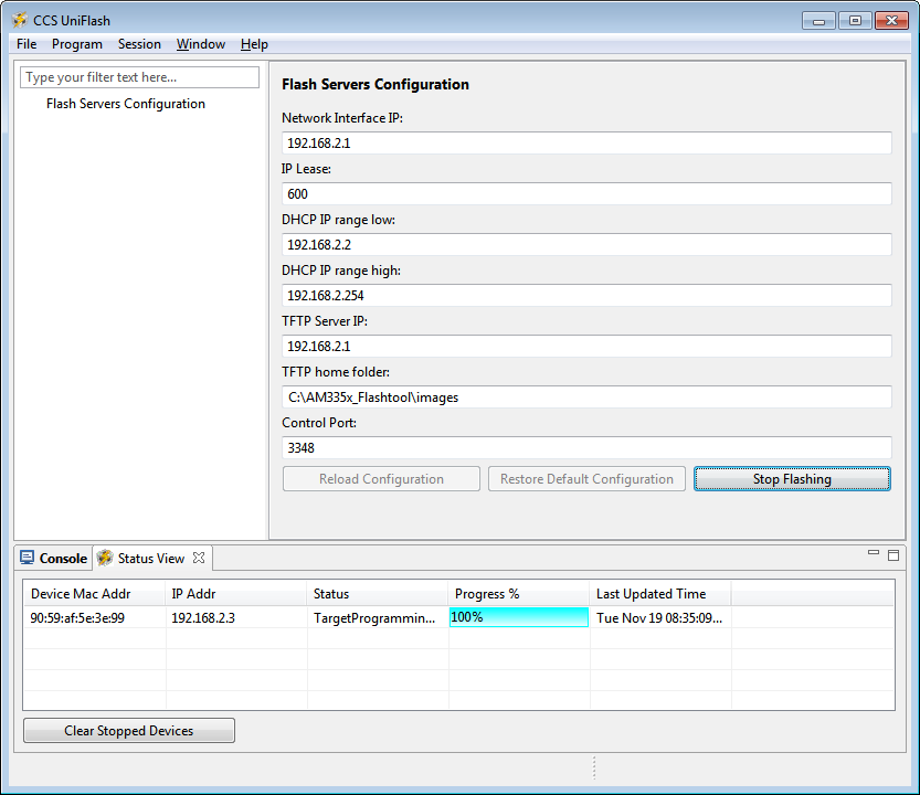
Note
The time the process takes to complete will vary considerably depending on a number of factors: the amount of data to be transferred to the target, the speed of the interface between the host and the target, the amount of data to be flashed, the write speed of the memory to be programmed, etc.
- To flash another target board, simply make a connection between it and the host PC through the switch. The board should start flashing automatically if powered and connected properly.
Flashing a Board using USB
To program a board using the USB interface between the host PC and the target board, the RNDIS protocol will be used to create a network connection over USB. A private network between the two will be established. The host PC is set up with a static IP address on one USB interface that ends up looking like a dedicated NIC (Network Interface Card) and connected directly to the target board.
Here is what you will need:
- Host PC with Uniflash installed and an available USB port.
- The files used to program the board put in the TFTP home folder as set up in Uniflash.
- A appropriate USB cable to connect the host PC and target board.
- Target board to be programmed.
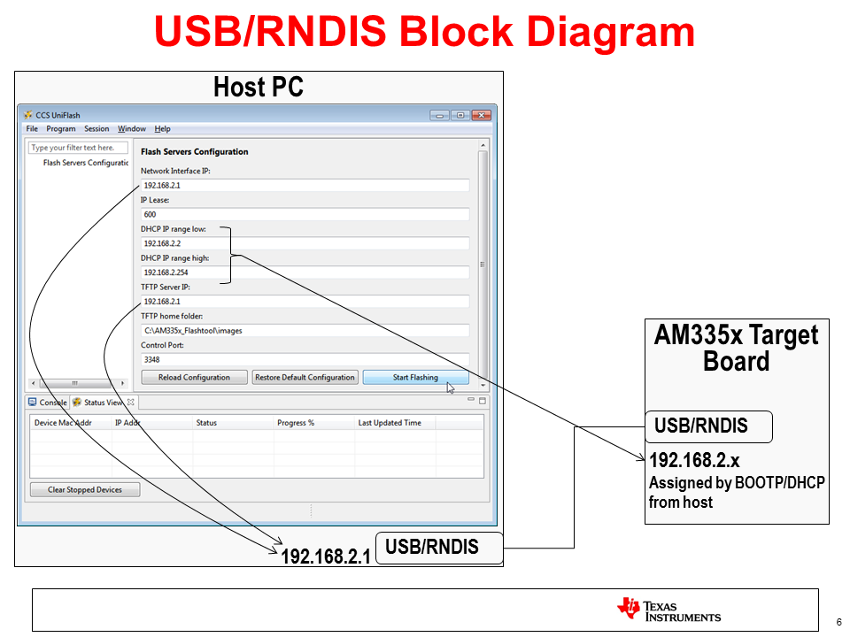
In order to establish a USB based RNDIS connection between the host and target, an appropriate driver needs to be installed on the host. A RNDIS driver is provided with Windows. This driver needs to be associated with 2 different steps in the flashing process and may have to be installed multiple times. Essentially, as the Sitara Processor on the target board moves through different stages of flashing process, it looks like a different USB device to Windows and the driver may need to be associated for each step. If it is not, that particular stage in the process will not be able to communicate over RNDIS and the process will fail.
This driver association should be handled automatically for AM335x. For AM43xx devices, this is a more manual process documented below. Either way, these steps could provide helpful information for either devices if problems are encountered.
- If Uniflash is not already running on the host PC, start it.
- Click on New Target Configuration.
- Set Connection to Sitara Flash Connections and Board or Device to Sitara Flash Devices. Click OK.
- Make sure the Flash Server Configuration is set up properly.
- Connect the host PC to the powered target board using an appropriate USB cable.
- This will prompt Windows to install a USB driver if a target board has never been plugged into that particular PC and that particular USB port on that PC. More than likely for the AM437x devices, this attempt will fail.
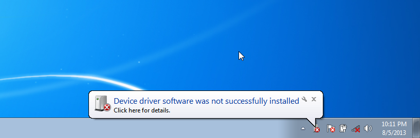
- Use Device Manager to install a USB driver. To open Device Manager, click on Start –> All Programs –> Right Click on Computer and Select Properties.
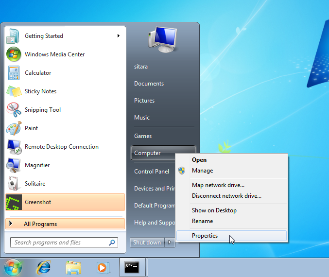
- Click on Device Manager in the window that opens.
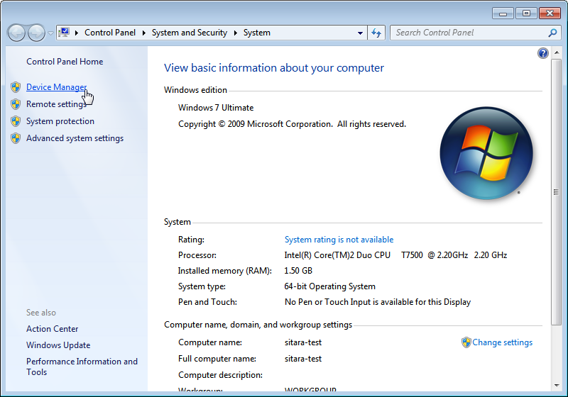
- Find the AM43xx1.2 Device listed in “Other Devices” per below. It will have a little yellow exclamation point on it indicating there is currently a problem with the device. Right click on it and select Update Driver Software….
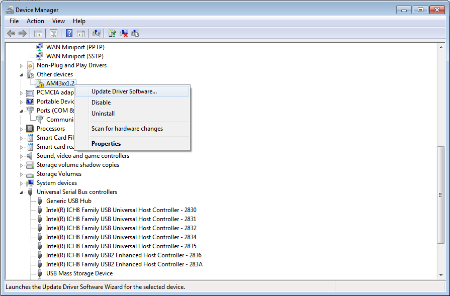
Note
If the device is not listed, it is probably because the operation has already timed out. Simply power cycle the target board to restart the process.
- In the Update Driver Software dialog, choose Browse my computer for driver software.
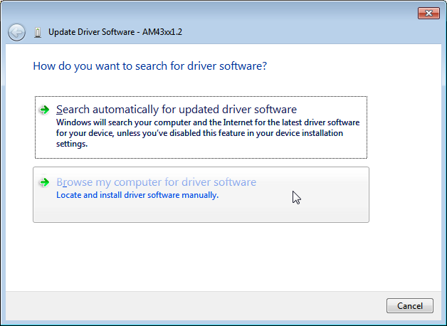
- Click Let me pick from a list in the next window:
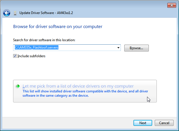
- Choose Network Adapter and click Next:
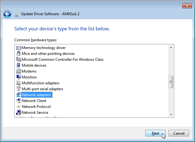
- Choose Microsoft Corporation as the Manufacturer and Remote NDIS6 based Device under adapter. Click Next:
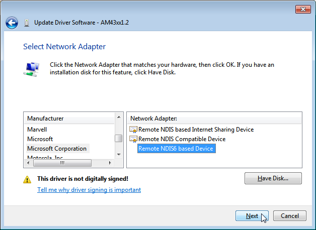
- If you see the following warning, click Yes:
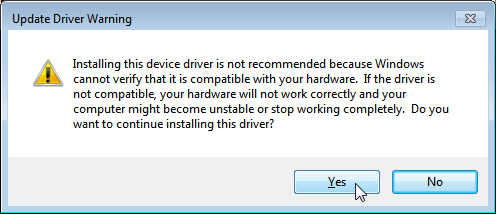
- You should receive a confirmation like below when the driver is successfully installed. Finally click Close.:
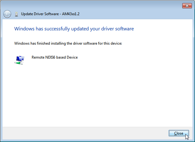
When the USB Driver for RNDIS is properly installed, it will create a new network interface. This can typically be seen in the lower right-hand corner of the toolbar:
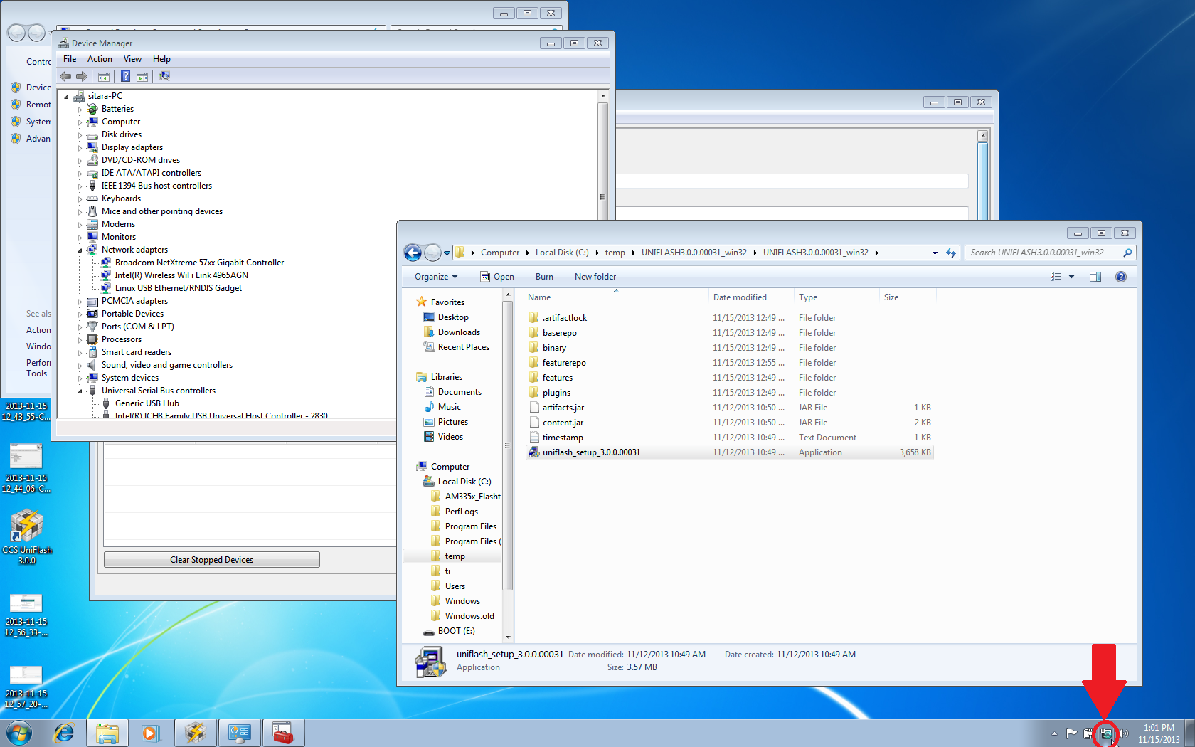
This new interface needs to be configured with a static IP address. Click on the Networking icon in the toolbar, and then click on the Open Network and Sharing Center link.
Inside the Network and Sharing Center, click on the new Internet Connection:
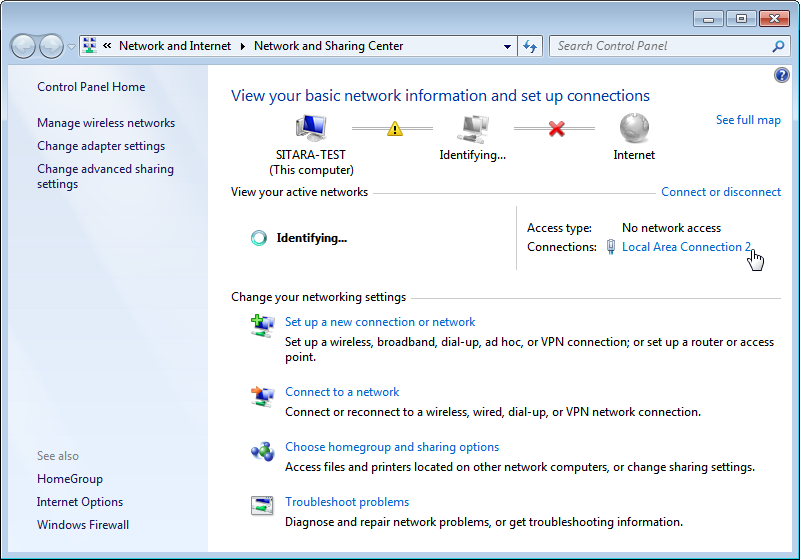
Note: The number next to the “Local Area Connection” will depend on the number of network connections the computer has. If this is the only network connection (i.e. the computer does not have an Ethernet or wireless networking connection), then this would be “1”. In most cases, computers have either a wired or wireless connection that will take up spot #1. Therefore, the new USB RNDIS Network Connection will be #2. However, if the computer has multiple connections already, then this number could be higher.
In the Connection Dialog, Click on Properties.

Select Internet Protocol Version 4 (TCP/IPv4) and choose Properties.
Set the port to use a Static IP Address by selecting Use the following IP Address: and changing the IP Address: to 192.168.2.1. This setting should correspond to the Network Interface IP setting in Uniflash. Verify that the Subnet Mask is set to 255.255.255.0 and click OK.
Note: It is possible to use other IP addresses. However, the IP address used needs to match the Uniflash configuration. If you prefer to use another address, you will need to change those configurations as well.
Click Close.
Click Close one more time to get back to the Network Manager. Let’s leave Network Manager open for now.
In Uniflash, enable the flashing capability by clicking on Start Flashing.
Depending on your Windows Firewall settings, you may get the below two warnings for the servers being used (opendhcp and opentftp). If so, please click Allow access.
Now that the IP connection has been configured, the target board should request the first file from the Uniflash via TFTP over USB/RNDIS. This is typically the SPL or MLO file for the first stage of the AM335x bootloader. If you do not see a new Flash process start in Uniflash, you may need to power cycle the target board. This restart is only necessary because the driver and network set up did not complete quickly enough. Now that it is configured, you should be able to progress to the next steps.
Once the first file is transferred from Host to Target, it will take over execution on the target board from the ROM on the Sitara device. This will cause another instance of the USB RNDIS driver to get created. Windows should use the previous steps to associate the driver to the device and create another instance. It is easy to watch this process in Device Manager by watching the Network Adapters section. If this does not happen, and the device driver fails to associate properly, you’ll need to use the steps above to install the USB driver for the new device.
When the second instance of the driver comes up, the new network interface will need to be configured like we did above. Open the Network Connection and Sharing Center, if it is not already open.
Inside the Network and Sharing Center, click on the new Internet Connection:
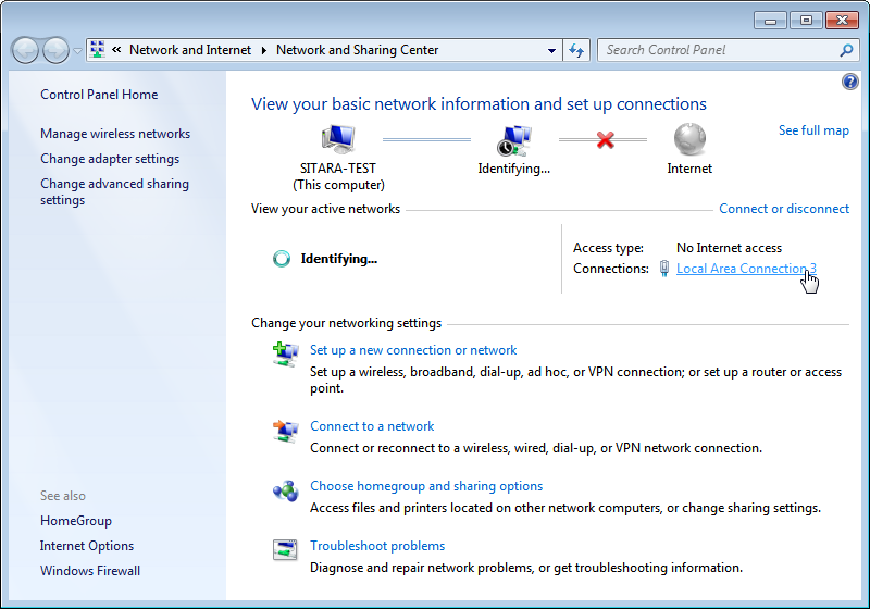
Note: The number next to the “Local Area Connection” will depend on the number of network connections the computer has. If this is the only network connection (i.e. the computer does not have an Ethernet or wireless networking connection), then this would be “1”. In most cases, computers have either a wired or wireless connection that will take up spot #1. Therefore, the new USB RNDIS Network Connection will be #3. However, if the computer has multiple connections already, then this number could be higher. Each new USB connection can increment this number.
In the Connection Dialog, Click on Properties.
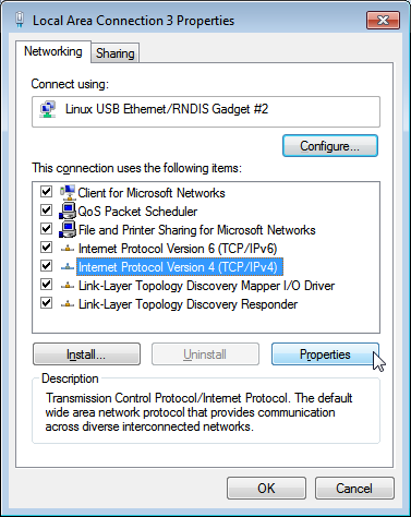
Select Internet Protocol Version 4 (TCP/IPv4) and choose Properties.
Set the port to use a Static IP Address by selecting Use the following IP Address: and changing the IP Address: to 192.168.2.1. This setting should correspond to the Network Interface IP setting in Uniflash. Verify that the Subnet Mask is set to 255.255.255.0 and click OK.
Note: It is possible to use other IP addresses. However, the IP address used needs to match the Uniflash configuration. If you prefer to use another address, you will need to change those configurations as well.
Click “No” if asked to remove other static configurations. Since we are using the same IP address for both RNDIS connections, Windows is trying to let us know that this is generally not a good idea. However, in this situation, the configuration ensures that both interfaces won’t be used at the same time.
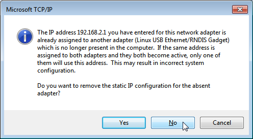
Click Close.
Click Close one more time to get back to the Network Manager.
Now that everything is configured, the process should be able to complete. Take a look at Uniflash and you should see the process progressing forward. If not, it might be necessary to start the process fresh by power cycling the Target Board. With everything set up correctly on the Host PC at this point, the process should be able to proceed without issue.
- When the flash process is complete, simply disconnect the target board. It should be flashed and ready for further testing.
- To flash another target board, simply make a connection between it and the Host PC by plugging a new powered target board into the USB cable. The board should start flashing automatically if powered and connected properly. Note: This process is tedious to set up the first time. However, once the Host PC is configured properly, programming new boards is as simple as plugging them in and flashing them.
USB Flash Programming Notes
- The USB/RNDIS set up is specific to each port on a given computer. If you follow the process above using one specific port, only that port is set up. If you plug a target board into a different port, the above process will need to be completed for that new port. Therefore, it is best to use the same USB port to avoid having to duplicate set ups.
- Uniflash v3.0 only supports programming one board at a time using USB.
- If you have trouble with RNDIS reporting problems in Device Manager, it mihgt be necessary to delete the RNDIS Driver and follow the above steps again to re-install it.
- For this entire process to work, there has to be two USB devices associated and each of them need to have their network addresses set up correctly. Essentially, at different steps in the process, the USB connected target board looks differently to Windows and it needs to have a driver and network set up for each. You can check this using Device Manager for USB and Network Manager for networking.
Useful Links
- Sitara Flash Programming Linux Development for AM335x/AM437x to learn more about developing images to be flashed using this process.
- Sitara Linux Program SPI Flash on AM335x EVM to see a specific example of how to program the SPI Flash an a AM335x EVM.
- More Uniflash information is available here.
3.5.2.2. AM335x Flash
Introduction
This document describes how to develop a flash imager for the Sitara AM335x/AM437x SoCs and how to prepare an image to be flashed. This information is focused on the Linux developer that is creating these images. The images, once created and tested, can be used to program Flash memory (NAND, NOR, SPI, QSPI or eMMC) attached to an AM335x/AM437x SoC on a target board. The flasher application and image to be flashed are transferred to what is expected to be a blank board (the flash has not been programmed before) via Ethernet or USB (using the Remote NDIS networking protocol). The flasher application and image can be hosted on either Linux or Windows. For Linux, we use standard tools that most developers are already familiar with for development, and this setup is further documented here. For Windows, we use CCS UniFlash. For more information on using CCS UniFlash with Sitara Devices, please see the Sitara Uniflash Quick Start Guide.
The overall process of programming the flash is broken into two parts:
- Developing the images to both be programmed and do the programming
from the AM335x/AM437x SoC. This is usually done by the Linux
developer responsible for creating the images. This process varies
somewhat depending on the desires of the Linux developer. There are 2
options defined below:
- Using U-Boot as the primary source of the flasher image. This works well for NAND, NOR, and (Q)SPI. It is the simplest process to use. Learn more about it here
- Using a Linux kernel and minimal filesystem. This is recommended for eMMC, but may have advantages in other situations as it makes the full power of Linux available to the flasher program. This is a bit more complex and may require a bit more porting. This process is documented here.
- Actually programming the images using Uniflash v3. This tool runs on a Windows PC and serves the images to the target board that is being programmed. This process is detailed in the Sitara Uniflash Quick Start Guide.
3.5.3. Pin Mux Tools
Introduction
The TI PinMux Tool is a Cloud, Windows, or Linux-based software tool for configuring pin multiplexing settings and I/O cell characteristics for TI Processors. Pin multiplexing controls the routing of internal signals to the external balls of the device while the I/O cell characteristics include enabling of internal pull-up / pull-down resistors. The Pin Mux Tool provides a graphical user interface for selecting the peripheral interfaces that will be used in the system design. Its intelligent solver atomatically selects pin combinations that help the designer make sure there are no multiplexing conflicts. All selections and settings can be saved as a pinmux design file which can be reloaded later.
Disclaimer
NOTE: Although these utilities are tested and intended to be accurate, they are provided ‘as is’ and are not guaranteed to provide accurate results. In the event of a conflict between the device data contained in this software tool and the device datasheet, the datasheet shall take precedence. Please check configuration results against the datasheet for your device to be assured your pinmux configuration is possible and accurate. It is up to the user to verify all of the bits in the registers based on the information in the device datasheet and that all IOSETs selected by the tool are valid and supported. Although we try to maintain backwards compatibility between PinMux Tool versions it isn’t guarunteed.
Software User’s Guide
A quick overview of the TI PinMux Tool’s UI and usage is available on the main PinMux Tool Wiki. The rest of this guide will focus on usage for the Sitara Processors.
Release Notes
Application Launch
At launch the tool will present the option to start a new design or to open an existing design. To start a new design use the drop-down menu indicating which devices are supported by this installation of the PinMux Tool. Select your device and click Start. Previously saved designs can be opened too. Although we try to maintain backwards compatibility between PinMux Tool versions it isn’t guarunteed.
IOSETs
Timing restrictions make the concept of IOSETs an important subject for Sitara Processors. The device datasheet timing specifications define the relationship between clock lines and data lines. A peripheral instance like McASP may be available on any number of pins but not all combinations of clock and data pins may be available. We only define IOSETs for combinations of pins that are guarunteed to meet the datasheet timing requirements. Pin conflict errors will be raised if the remaining available pins don’t come together to build an IOSET or if pins are manually selected that don’t match a defined IOSET. This is why it is important to start your system design with the PinMux Tool first before any schematic or board design is started.
Use Cases
Some peripherals may expose Use Cases to allow you to quickly eliminate the signals you won’t need.
AM57xx and MCASP
On the AM57xx series of devices there is a concept of IODELAY. It is a module in the IO of the SoC that makes it possible to ensure valid IO timings on data interfaces with a clock signal. On some peripherals the use case selected can change the IODELAY setting for an IO. MCASP is an advanced audio interface that allows each AXR pin to be an audio source or audio sink, it also allows the SoC to be the clock master or slave, and these configuration can be independently mixed and matched. This makes it important to select the correct use case and pin configurations since the IODELAY configuration changes depending on the options chosen. See the “Virtual Mode Case Details” tables in the datasheet for more information.
Power Domain Checking
Some devices support dual-voltage inputs on the IO pins (VDDSHVx). The PinMux Tool is capable of tracking the IO power supply domains of an SoC and allows you to select which voltage is applied on the dual-voltage IO rails. With this information the PinMux Tool can raise a voltage conflict warning if a peripheral’s IO requires a different voltage than is applied to the dual-voltage IO rail.
Example: On the AM57xx pin B14 is supplied by VDDSHV3. If gpio5_0 is used on this pin, the IO will be either 1.8V or 3.3V depending on the supply level applied to VDDSHV3. Damage may occur to the SoC pin if a 3.3V signal was driven into gpio5_0 while it is operating at 1.8V.
Changing Pad Configuration Parameters
Pad configuration parameters are used to set the values of other bit fields in each Pad Configuration Register. The parameters are typically for internal resistor pull and a check box for enabling receive functionality. These configuration parameters are SoC specific and may vary.
K2Gxx
The pins on this device have a “buffer class” feature that lets you fine tune the output driver characteristics. For most I/Os the options are “Class B - Up to 100MHz” or “Class D - Up to 200MHz”. The PinMux Tool gives you the option to select the buffer class for pins that support this feature (differential or SerDes I/Os for example don’t support it).
RX Enable / Input Enable
Most devices, K2G excluded, support the ability to disable the input buffer on a pin. When the RX buffer is disabled the pin can still be used as an output for clocks and GPIO but it cannot be used as an input for any function. Many peripherals require the input buffer to be enabled even if it is an output. Examples are I2C clock, MDIO clock, SPI chip select, MMC/SD clock & cmd lines, etc. For the most part, the PinMux Tool will not let you disable the input buffer on pins that require it.
Output File Formats
Code files generated by the PinMux Tool vary by each device and its requirements. They generally include C code for Processor SDK RTOS which should be drop-in compatibile with the PDK Board Library. Reference the Processor SDK RTOS Board Support page for more details. A partial devicetree format is generated for Processor SDK Linux and that should be manually patched into the reference devicetree file included with the Linux kernel.
Some devices will have a generic format that is intended for use with U-boot. These devices require pin multiplexing to be done once, in isolation, and while executing from SRAM. U-boot takes care of this by applying pin configurations while the MLO file (secondary bootloader) executes from OCMC RAM. This guide will include how to convert the generic format for U-boot.
Processor SDK RTOS
After updating the files in the directories below you will need to recompile the board_lib and sbl components of the Processor SDK Platform Development Kit (PDK). Follow this guide on Rebuilding The PDK.
AM3, AM4, AMIC
Replace files in this directory
${PDK_INSTALL_DIR}\packages\ti\starterware\board\${SOC}\ File names will need to be prefixed by “${SOC}_”. Pinmux header file is common for each SOC here, and may need to be updated manually.
Everything Else (AM5, K2G)
Replace files in this directory
${PDK_INSTALL_DIR}\packages\ti\board\src\${BOARD}\
Processor SDK Linux
Recompiling u-boot is required after making updates. Instructions are available in the Linux_Core_U-Boot_User’s_Guide. Compiling the devicetree dts to dtb is also required after making updates. Instructions are available in the Linux Kernel Users Guide
devicetree
Edit the appropriate file in this directory/
${SDK_INSTALL_DIR}\board_support\linux-*\arch\arm\boot\dts\${BOARD}.dts
AM57xx u-boot
The PinMux tool will provide two files: genericFileFormatIOdelay.txt and genericFileFormatPadConf.txt. A perl script is provided to convert the generic formats and provide a format that can be used in u-boot. The script and the instructions to run the script are on git.ti.com. The output from the script is used to edit the file in this directory.
${SDK_INSTALL_DIR}\board_support\u-boot-*\board\ti\am57xx\mux_data.h
K2G u-boot
Replace the file in this directory.
${SDK_INSTALL_DIR}\board_support\u-boot-*\board\ti\ks2_evm\mux-k2g.h
AM3 and AM4 u-boot
The PinMux Tool does not export any u-boot files for these devices. But the file below may still need to be modified.
${SDK_INSTALL_DIR}\board_support\u-boot-*\board\ti\am335x\mux.c
${SDK_INSTALL_DIR}\board_support\u-boot-*\board\ti\am43xx\mux.c
3.5.4. Code Composer Studio
3.5.4.1. CCS Installation
Overview
Code Composer Studio (CCS) is the IDE integrated with the Processor Linux SDK and resides on your host Ubuntu machine. This wiki article covers the CCS basics including installation, importing/creating projects and building projects. It also provides links to other CCS wiki pages including debugging through GDB and JTAG and accessing your target device remotely through Remote System Explorer.
CCS is an optional tool for the SDK, and may be downloaded and installed at the same time that the SDK is installed or at a later date. For instructions on how to download the Processor Linux SDK, please see Processor SDK Linux Installer.
CCS uses the Eclipse backend and includes the following plugins:
- Remote System Explorer - provides tools which allow easy access to the remote target board
- Cross-compile for GCC- allows easy access to the Linaro GCC-based compiler included in the Processor Linux SDK
NOTE You should download CCS from the Processor Linux SDK Download page because it comes with the above plug-ins already installed. Otherwise, you will have to install the plug-ins yourself in order to take advantage of all the features covered in the wiki help pages and wiki training pages.
Prerequisites
If you wish to use CCS along with the Processor Linux SDK, there are requirements to consider before you attempt to install and run CCS. To be prepared for development, you should have already setup your host Linux machine and you should already have your target board up and running. Additionally, you should be able to communicate from the host to the target with serial and Ethernet communication.
For more information on setting up your development environment, see the Processor SDK Linux Getting Started Guide.
Toolchain
The Processor Linux SDK comes with an integrated Linaro GCC toolchain located on your Ubuntu host. CCS is integated with the SDK allowing you to build, load, run and debug code on the target device. In more recent SDK versions (v06.00, v08.00, v01.00.00.00, v02.00.00.00, etc) for non-ARM 9 devices, a new Linaro based toolchain is used and the location of the toolchain has changed. For more information on the GCC toolchain, please see Processor Linux SDK GCC Toolchain.
Latest SDK toolchains use a prefix of arm-linux-gnueabihf-. Versions older than Processor Linux SDK 06.00 and AM18x users may still use the prefix arm-arago-linux-gnueabi-.
Locating the CCS Installer
Using the SD Card Provided with the EVM
When the SD card provided in the box with the EVM is inserted into an SD card reader attached to a Linux system three partitions will be mounted. The third partition, labeled START_HERE, will contain the CCS installer along with the Processor Linux SDK installer. The CCS installer is located inside of the CCS directory and there is a helper script called ccs_install.sh available to help call the installer.
Downloading from the Web
The CCS installer is available for download for Linux as a compressed tarball (tar.gz) file. It is also available for Windows. The installer can be located by browsing to SDK for Sitara Processors and selecting the device being used. The CCS installer can be found on the device’s SDK installer page under the Optional Addons or directly from the Download CCS wiki page.
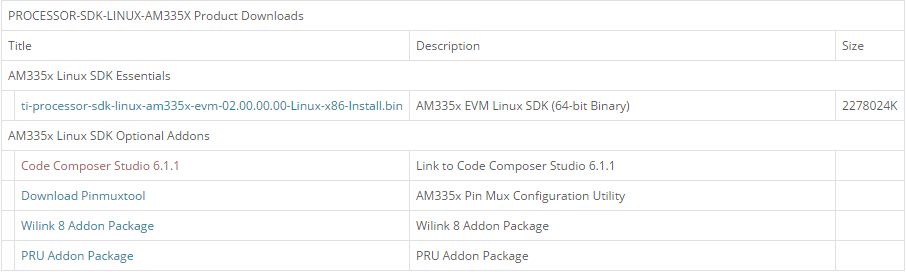
Clicking this link will prompt you to fill out an export restriction form. After filling out the form, you will be given a download button to download the file and you will receive an e-mail with the download link. Download the tarball and save it to your Linux host development system.
Starting the CCS Installer
Installing CCS from the Linux Command Line
If you want to install CCS apart from the Processor Linux SDK installer, or if you decided not to install it as part of the SDK install and want to install it now, you can install CCS using the following commands:
- Open a Linux terminal and change directory to the location where the CCS tarball is located. This may be the START_HERE partition of the SD card or the location where you downloaded the file from ti.com or the wiki page.
- If the CCS files are still in a compressed tarball, extract them. <version> is the version string of the CCS installer. tar -xzf CCS<version>_web_linux.tar.gz
- Begin the installer by executing the binary (.bin) file extracted. ./ccs_setup_<version>.bin
CCS Installation Steps
NOTE The “Limited 90-day period” language in the CCS installer license agreement applies only for the case of using high-speed JTAG emulators (does not apply to use of the XDS100v2 JTAG emulator or an on-board emulator). If a debug configuration is used that requires a high-speed JTAG emulator, you will be prompted to register your software for a fee. All use of CCS (excluding use of high-speed JTAG emulators) is free and has no 90-day time limit.
When the CCS installer runs, you can greatly reduced the install time and installed disk space usage by taking the defaults as they appear in this CCS installer. The screen captures below show the default installation options and the recommended settings when installing CCS.
- The License Agreement screen will prompt you to accept the terms of the license agreement. Please read these terms and if you agree, select I accept the terms of the license agreement. If not, then please exit the installation.
- At the Choose Installation Location just hit “Next” to install at the default location. If you want the SDK installed at a different location then select “Browse” and pick another location.
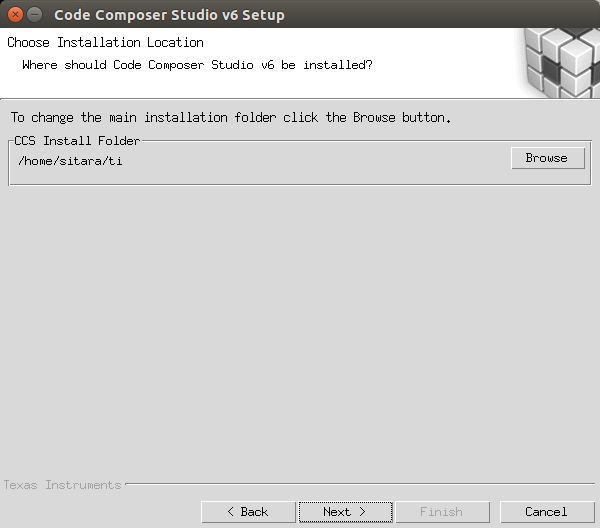
- At the Processor Support screen make sure to select the Sitara ARM 32-bit processors option. You should not select “GCC ARM Compiler” or “TI ARM Compiler”, because you will be using the Linaro toolchain that comes with the Processor Linux SDK installation.
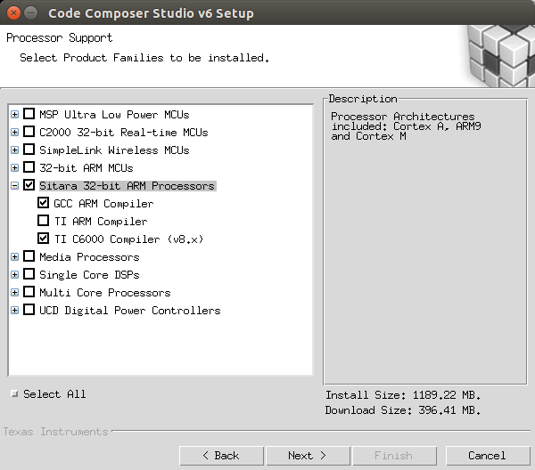
- At the Select Emulators screen, select any emulators that you have and want to use. This is an optional feature you can use for debugging via JTAG.
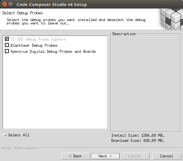
- At the APP Center screen none of the options should be selected, click Finish to begin installation.
- Now the installation process starts and this can take some time.
- After installation is complete, you should see the following screen, hit finish and installation is complete.
Installing Emulator Support
If during the CCS installation you selected to install drivers for the Blackhawk or Spectrum Digital JTAG emulators, a script must be run with administrator privileges to allow the Linux Host PC to recognize the JTAG emulator. The script must be run as “sudo” with the following command:
sudo <CCS_INSTALL_PATH>/ccsv6/install_scripts/install_drivers.sh where <CCS_INSTALL_PATH> is the path that was chosen when the CCS installer was run.
Launching CCS
- Double-Click the Code Composer Studio v6 icon on the desktop. You will see a splash screen appear while CCS loads.

- The next window will be the Workspace Launcher window which will ask you where you want to locate your CCSv6 workspace. Use the default value.
- CCS will load the workspace and then launch to the default TI Resource Explorer screen.
- Close the TI Resource Explorer screen. This screen is useful when making TI CCS projects which use TI tools. The Processor Linux SDK uses open source tools with the standard Eclipse features and therefore does not use the TI Resource Explorer. You will be left in the Project Explorer default view.
Enabling CCS Capabilities
Each time CCS is started using a new workspace, perspectives for additional capabilities will need to be enabled. These are selectable in the Window -> Open Perspectives list.
After opening CCS with a new workspace:
- Open the Window -> Preferences menu.
- Go to the General -> Capabilities menu.
- Select the RSE Project Capability.
- Click Apply and then OK. This enables the perspectives in the Window -> Open Perspective -> Other menu, as shown below, and is needed to make the Remote System Explorer plug-ins selectable.
Importing C/C++ Projects
Importing the Projects
- Launch CCSv6 and load the default workspace.
- From the main CCSv6 window, select File -> Import... menu item to open the import dialog.
- Select the General -> Existing Projects into Workspace option.
- Click Next.
- On the Import Projects page click Browse.
- In the file browser window that is opened navigate to the <SDK INSTALL DIR>/example-applications directory and click OK.
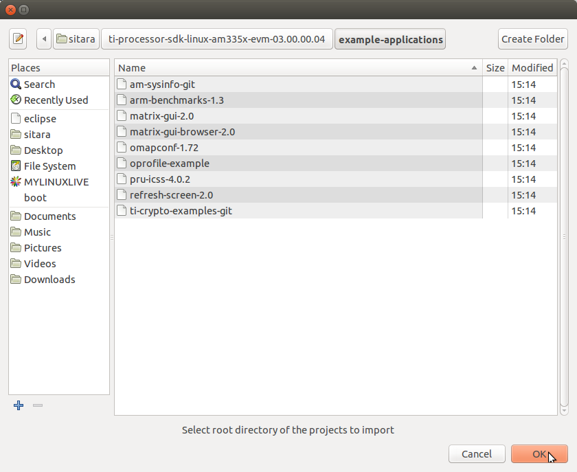
- The Projects: list will now be populated with the projects found.
- Uncheck the following projects. They are Qt projects and are imported
using a different method. For more information, see the Hands on
with QT
training.
- matrix_browser
- refresh_screen
- Select the projects you want to import. The following screen capture shows importing all of the example projects for an ARM-Cortex device, excluding the matrix_browser project.
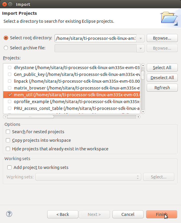
- Click Finish to import all of the selected projects.
- You can now see all of the projects listed in the Project Explorer tab.
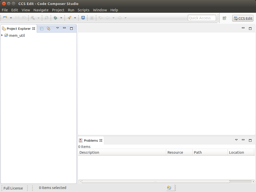
Building the C/C++ Projects
In order to build one of the projects, use the following steps. For this example we will use the mem-util project.
Right-Click on the mem-util project in the Project Explorer.
Select the build configuration you want to use.
- For Release builds: Build Configurations -> Set Active -> Release
- For Debug builds: Build Configurations -> Set Active -> Debug
Select Project -> Build Project to build the highlighted project.
Expand the mem-util project and look at the mem_util.elf file in the Debug or Release directory (depending on which build configuration you used). You should see the file marked as an [arm/le] file which means it was compiled for the ARM.
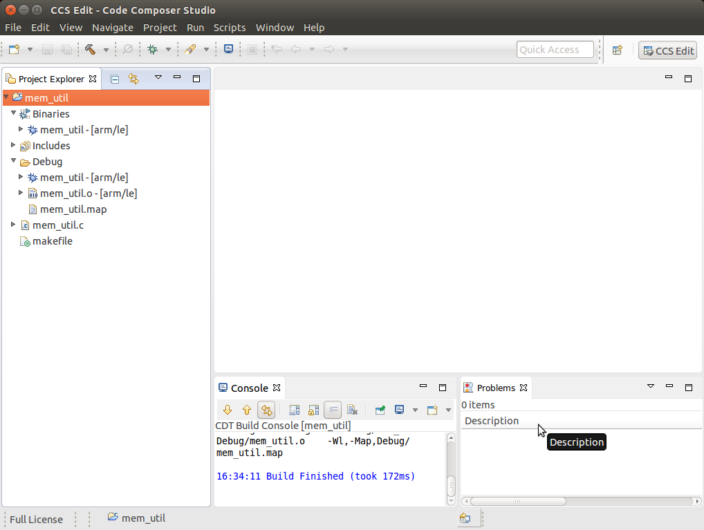
NOTE You can use Project -> Build All to build all of the projects in the Project Explorer.
Installing C/C++ Projects
There are several methods for copying the executable files to the target file system:
Use the top-level Makefile in the SDK install directory. See Processor Linux SDK Top-Level Makefile for details of using the top-level Makefile to install files to a target file system. This target file system can be moved via an SD card connected to the host machine and then to the target board, transferred via TFTP, or some other method. For more information on setting up a target filesystem, see Processor SDK Linux Setup Script.
NOTE The top-level Makefile uses the install commands in the component Makefiles and can be used as a reference for how to invoke the install commands.
For all file system types, you can also transfer the file using the drag-and-drop method of Remote System Explorer. See the Remote System Explorer section below for more details.
Files can also be moved from the Linux command line. Typically, executable files are stored in the project’s Debug folder in the workspace.
Creating a New Project
This section will cover how to create a new cross-compile project to build a simple Hello World application for the target.
Configuring the Project
From the main CCSv6 window, select File -> New -> Project... menu item.
In the Select a wizard window, select the C/C++ -> C Project wizard.

Click Next.
In the C Project dialog set the following values: Project Name: helloworld Project type: Executable -> Empty Project Toolchains: Cross GCC
Click Next.
In the Select Configurations dialog, you can take the default Debug and Release configurations or add/remove more if you want.
Click Next.
In the Command dialog, set the following values: Tool command prefix: arm-linux-gnueabihf-.
NOTE The prefix ends with a “-”. This is the prefix of the cross-compiler tools as will be seen when setting the Tool command path.
Tool command path: /home/sitara/ti-sdk-<machine>-<version>/linux-devkit/sysroots/<Arago Linux>/usr/bin
Use the Browse.. button to browse to the Sitra Linux SDK installation directory and then to the linux-devkit/sysroots/<Arago Linux>/usr/bin directory. You should see a list of tools such as gcc with the prefix you entered above.
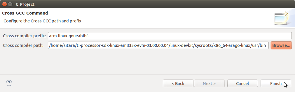
Click Finish.
After completing the steps above you should now have a helloworld project in your CCS Project Explorer window, but the project has no sources.
Adding Sources to the Project
From the main CCS window select File -> New> Source File menu item.
In the Source File dialog set the Source file: setting to helloworld.c
Click Finish.
After completing the steps above you will have a template helloworld.c file. Add your code to this file like the image below:
Compile the helloworld project by selecting Project -> Build Project
The resulting executable can be found in the Debug directory.
Remote System Explorer
CCS as installed with this SDK includes the Remote System Explorer (RSE) plugin. RSE provides drag-and-drop access to the target file system as well as remote shell and remote terminal views within CCS. Refer to Processor Linux SDK CCS Remote System Explorer Setup to establish a connection to your target EVM and start using RSE. There is also a more detailed training using RSE with the SDK at Processor SDK Linux Training: Hands on with the Linux SDK.
Using GDB Server in CCS for Linux Debugging
In order to debug Linux code using Code Composer Studio, you first need to configure the GDB server on both the host and target EVM side.
Please refer to Processor Linux SDK CCS GDB Setup for more information.
3.5.4.2. CCS Compiling
Overview
Code Composer Studio (CCS) v6.0 is the IDE integrated with the Sitara SDK and resides on your host Ubuntu machine. This wiki article covers the CCS basics including installation, importing/creating projects and building projects. It also provides links to other CCS wiki pages including debugging through both GDB and JTAG and accessing your target device remotely through remote system explorer.
Prerequisites
If you wish to use CCS along with the Sitara Linux SDK, there are some setup steps required before you attempt to install and run CCS.
- You need to be prepared for development. This means you should have
already setup your host linux machine and you should already have
your target up and running. Additionally you should be able to
communicate from host to target with both the following:
- Serial communication for linux boot and linux debug
- Ethernet communication for utilizing some of the CCS debug file sharing capabilities
See this link to meet the above requirements: Sitara_Linux_SDK_Getting_Started_Guide#Start_your_Linux_Development
Building Qt Applications
Although the Processor Linux SDK includes several Qt example applications using Code Composer Studio to build or debug these applications isn’t recommended. QT Creator is the official IDE designed to be used when developing or debugging Qt applications.Please reference to the following link for further information on all the basic to download, install, run, and debug QT applications: Hands on with Qt
Importing Existing C/C++ Projects
The Processor Linux SDK includes several example applications that already includes the appropriate CCS Project files. The following instructions will help you to import the example C/C++ application projects into CCS.
Importing the Project
From the main CCS window, select File -> Import... menu item to open the import dialog
Select the General -> Existing Projects into Workspace option

Click Next
On the Import Projects page click Browse
In the file browser window that is opened navigate to the <SDK INSTALL DIR>/example-applications directory and click OK
Select the projects you want to import. The following screen capture shows importing all of the example projects for an ARM-Cortex device, excluding the Qt projects.
- Click Finish to import all of the selected projects.
- You can now see all of the projects listed in the Project Explorer tab.
Creating a New Project
This section will cover how to create a new cross-compile project to build a simple Hello World application for the target.
Configuring the Project
From the main CCS window, select File -> New -> Project... menu item
in the Select a wizard window select the C/C++ -> C Project wizard
Click Next
In the C Project dialog set the following values: Project Name: helloworld Project type: Cross-Compile Project
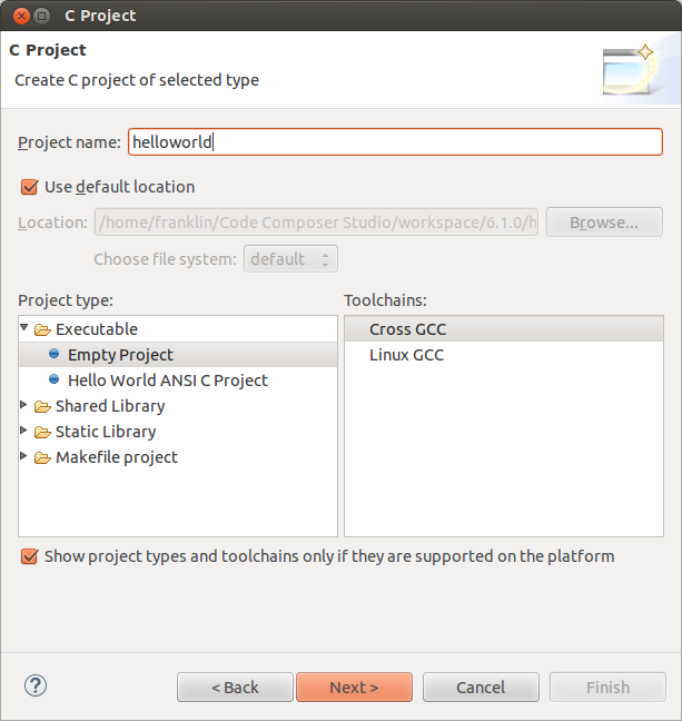
Click Next
In the Command dialog set the following values: Tool command prefix: arm-linux-gnueabihf-. Note the the prefix ends with a “-”. This is the prefix of the cross-compiler tools as will be seen when setting the Tool command path Tool command path: <SDK INSTALL DIR>/linux-devkit/sysroot/i686-arago-linux/usr/bin. Use the Browse.. button to browse to the Sitra Linux SDK installation directory and then to the linux-devkit/bin directory. You should see a list of tools such as gcc with the prefix you entered above.
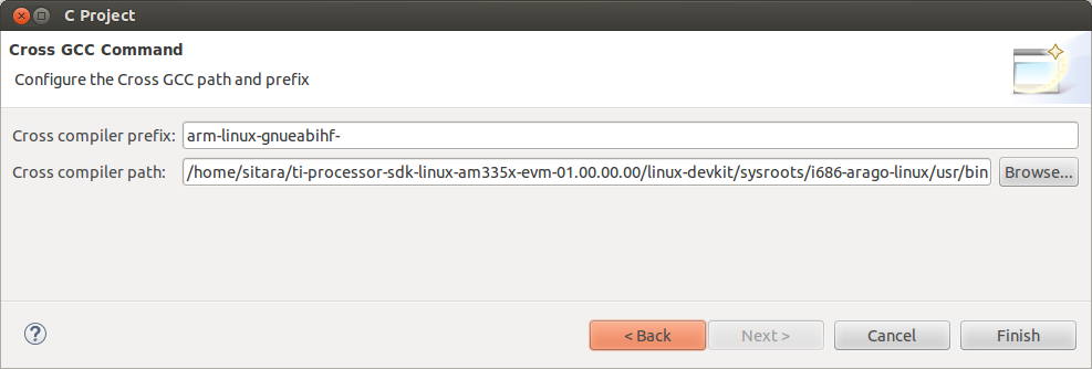
Click Next
In the Select Configurations dialog you can take the default Debug and Release configurations or add/remove more if you want.
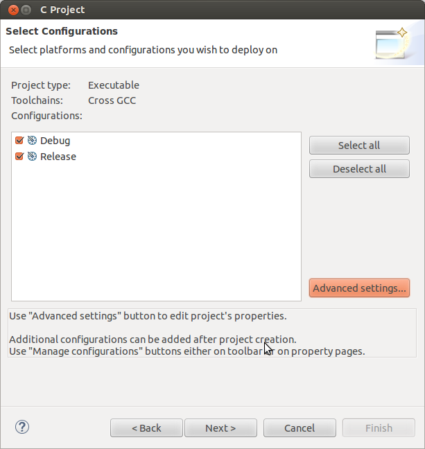
Click Finish
Adding Sources to the Project
After completing the steps above you should now have a helloworld project in your CCS Project Explorer window, but the project has no sources.
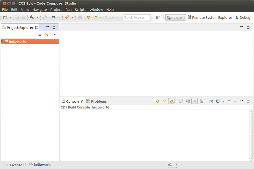
From the main CCS window select File -> New -> Source File menu item
In the Source File dialog set the Source file: setting to helloworld.c
Click Finish
After completing the steps above you will have a template helloworld.c file. Add your code to this file like the image below:
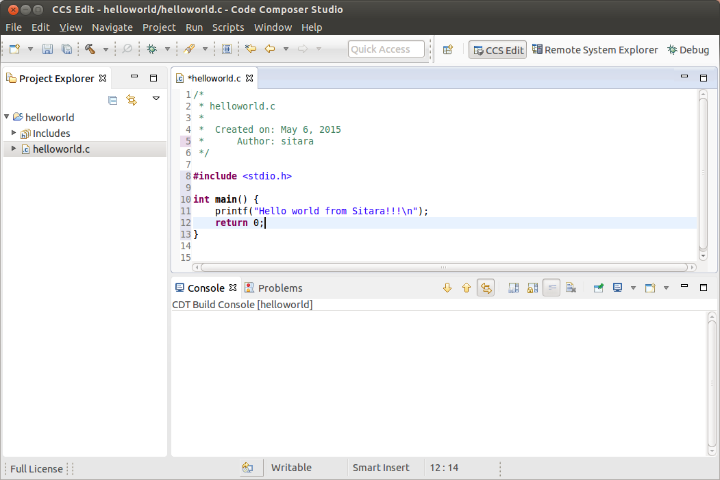
Compiling C/C++ Projects
Right-Click on the project in the Project Explorer
Select the build configuration you want to use
- For Release builds: Build Configurations -> Set Active -> Release
- For Debug builds: Build Configurations -> Set Active -> Debug
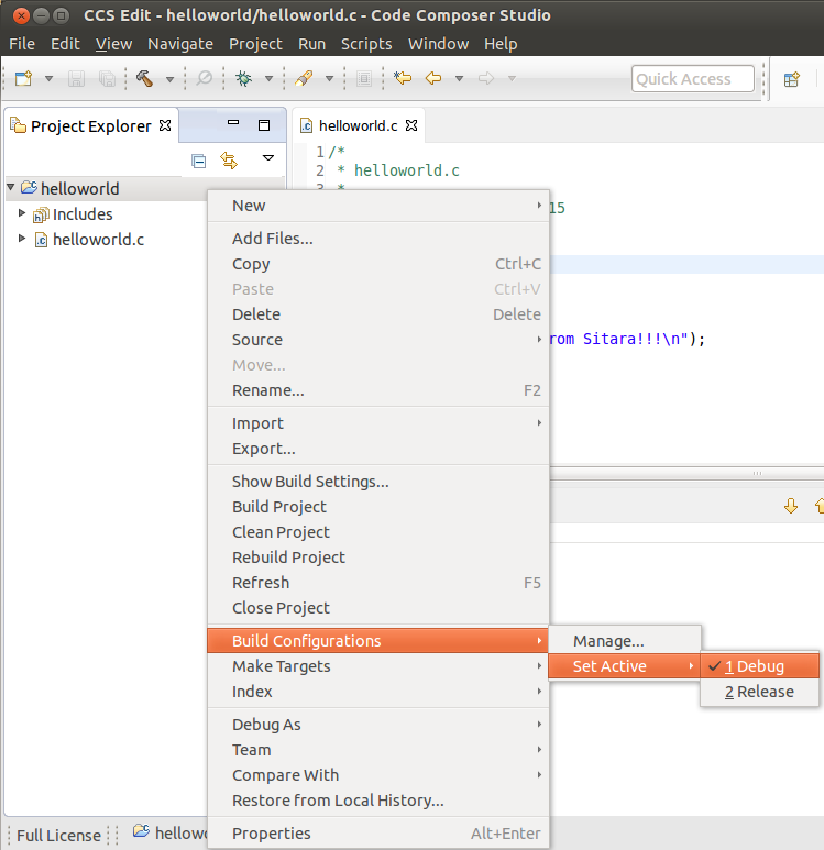
Select Project -> Build Project to build the highlighted project
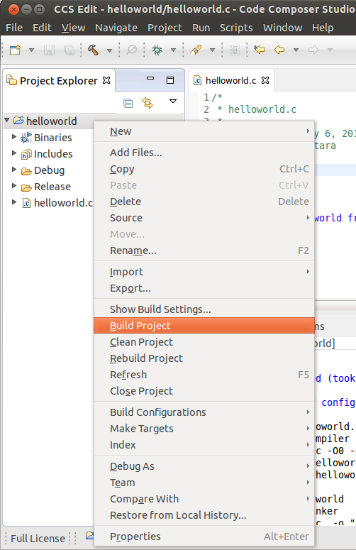
- NOTE: You can use Project -> Build All to build all of the projects in the Project Explorer
Next Steps
Copying Binaries to the File system
There are several methods for copying the executable files to the target file system:
- Copying files manually to the SD card root file system
- If NFS is being used, copying the files manually to the NFS file system
- Using Code Composer Studio to automatically copy the executable to the target evm using Remote System Explorer
Remote System Explorer
CCS v6 by default includes the Remote System Explorer (RSE) plug-in. RSE provides drag-and-drop access to the target file system as well as remote shell and remote terminal views within CCS. It also provides a way for Code Composer Studio to automatically copy and run or debug an executable using a single button. Refer to How to Setup and Use Remote System Explorer to learn how to use this feature.
Debugging Source Code using Code Composer Studio
In order to debug user-space Linux code using Code Composer Studio v6, you first need to configure your project to use gdb and gdbserver included within the SDK.
Please refer to Debugging using GDB with Code Composer Studio for more information.
3.5.4.3. Remote Explorer Setup with CCS
Overview
Remote System Explorer (RSE) is an Eclipse plug-in that provides:
- Drag-and-drop access to the remote file system
- Remote shell execution
- Remote terminal
- Remote process monitor
Prerequisites
Before you configure RSE you should make sure the following prerequisites are met:
- Installed the Processor Linux SDK
- Installed Code Composer Studio
- Created or imported a C/C++ Project. This project should be already open.
- Connected your host PC and evm to the same network. Your PC and EVM should be on the same subnet.
- Know the IP of your evm.
- You can obtain the IP address of the EVM using matrix and selecting Settings -> Network Settings or by connecting over the serial console and using the ifconfig command.
Opening the Remote System Explorer Perspective
- Go to Window -> Open Perspective -> Other...
- In the menu window select Remote System Explorer to open this perspective.
- Click OK
- You will now have the RSE view opened
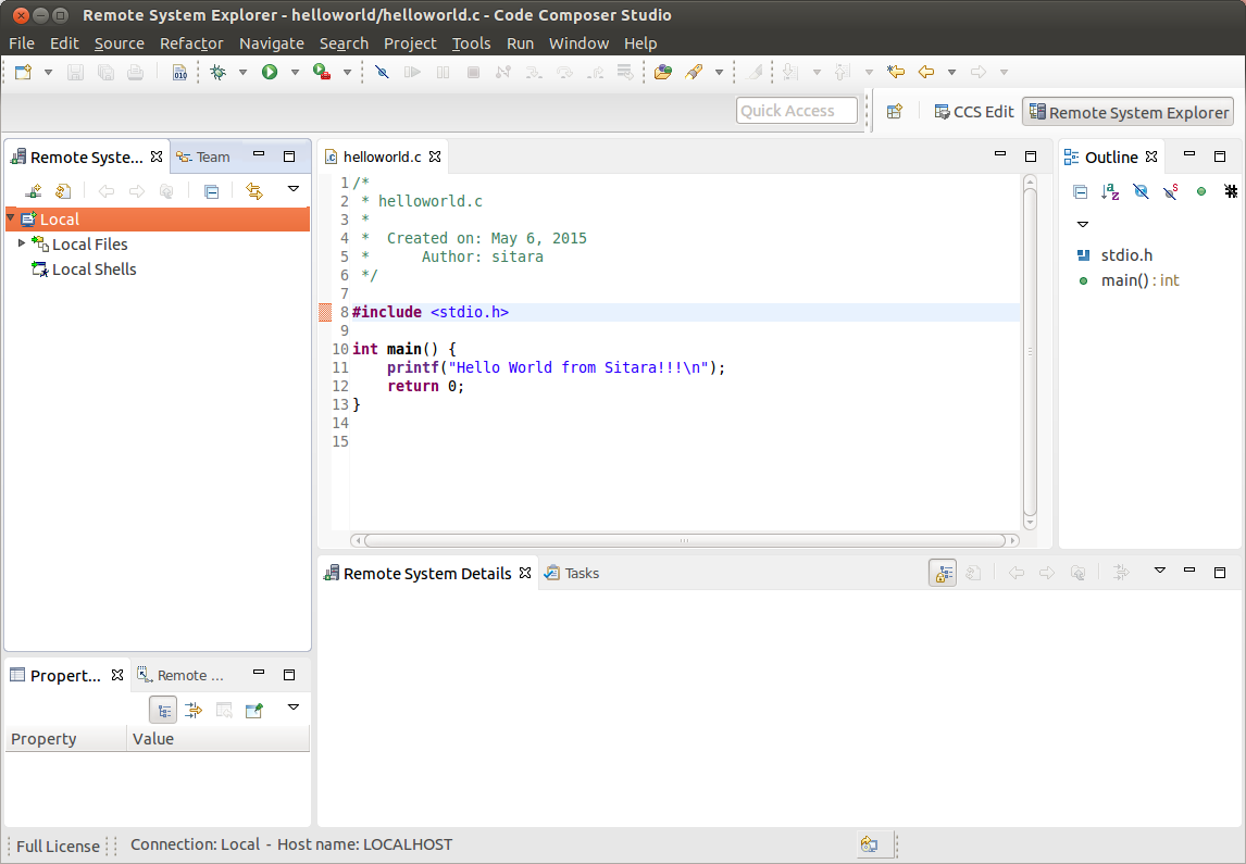
Creating a New Connection
To establish a new connection with the target EVM you must run the New Connection Wizard.
- Click File -> New -> Other...
- In the Select a wizard window select Remote System Explorer -> Connection
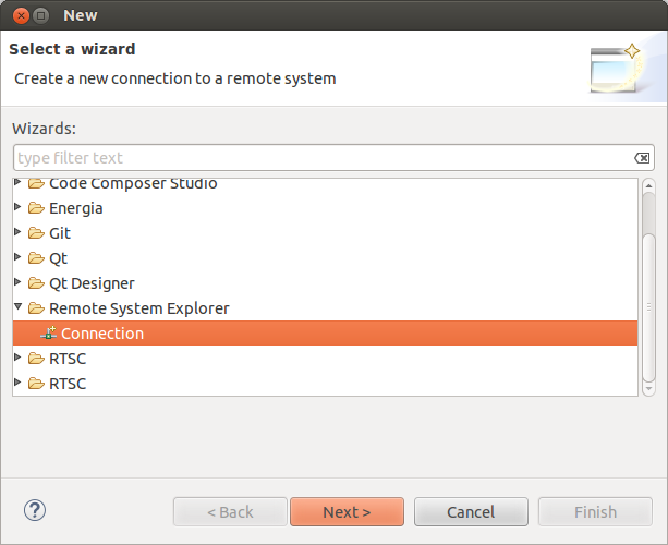
- Click Next
- In the Select Remote System Type window select the Linux system type
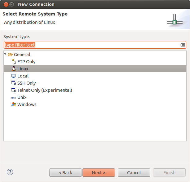
- Click Next
- In the Remote Linux System Connection window enter Host name: Enter the IP address of your target EVM. This can be determined as detailed in the **Prerequisites** section above Connection name: The default value is the same as the host name, but this can be changed to a more human readable value like Target EVM You can un-check Verify host name or leave it checked depending on whether you want to verify the IP address you entered for the Host name field.
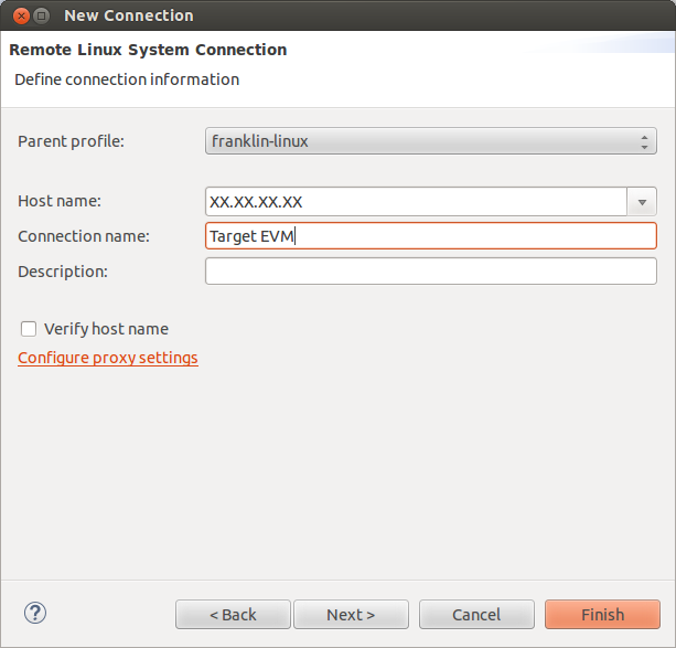
- Do NOT click the Finish button. Click Next
- Check ssh.files to use the Secure Shell protocol for communication
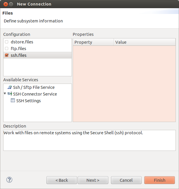
- Do NOT click the Finish button. Click Next
- Check processes.shell.linux to use a shell to work with processes on the remote system
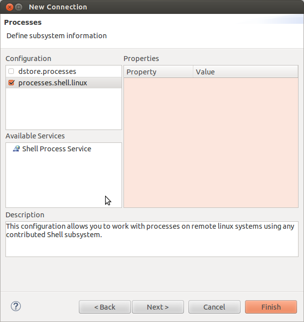
- Do NOT click the Finish button. Click Next
- Check ssh.shells to use Secure Shell to work will shell commands
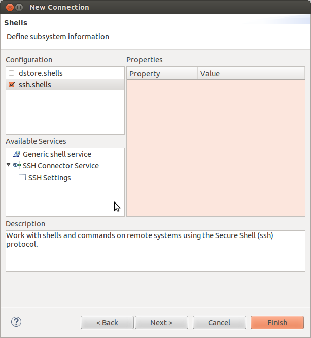
- Do NOT click the Finish button. Click Next
- Check ssh.terminals to use Secure Shell to work with terminals
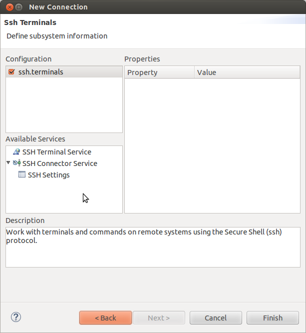
- Click Finish
- You will now see your EVM configuration in the RSE view
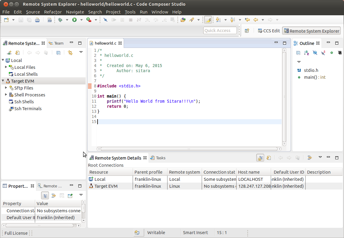
Re-Opening the C/C++ View
If when you enabled RSE and opened the RSE perspective your C/C++ view disappeared you can re-open it using the following commands. This is useful to get back to your projects list to enable copying and pasting files to transfer to the remote system.
- Select Window -> Show View -> Other...
- In the Show View dialog select C/C++ -> C/C++ Projects
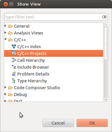
- Click OK
- NOTE: If you do not like the location of the C/C++ Projects view you can drag it to another location in CCS my dragging and dropping the Tab.
Re-Opening the Remote System Explorer View
If you have closed the RSE view and wish to re-open it you can use these steps:
- Select Window -> Show View -> Other...
- In the Show View dialog select Remote Systems -> Remote Systems
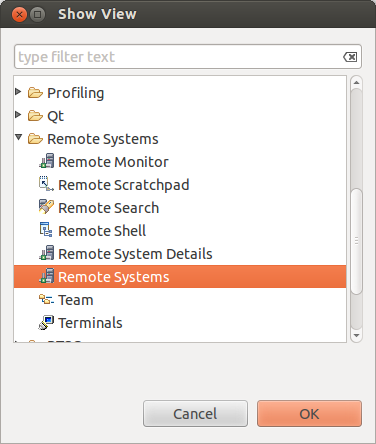
- Click OK
- NOTE: If you do not like the location of the Remote Systems view you can drag it to another location in CCS my dragging and dropping the Tab.
- A Remote Systems tab appears in the CCS perspective. The target connection named Target EVM is shown in a tree structure with branches for the various Remote System functions which communicate with the target EVM using a secure SSH connection. Sftp Files - Provides a drag and drop GUI interface to the target file system. Shell Processes - Provides a listing of processes running on the remote system and allows processes to be remotely killed. Ssh Shells - Provides a Linux shell window for the remote system within CCS. Ssh Terminals - Provides a terminal window for the remote system within CCS.
Configuring with a Proxy
In the case that you are behind a proxy (most corporate networks) you may need to configure CCS to bypass all proxies. You want to make sure you also bypass the proxy for your target devices so that your connection does not attempt to go out the proxy and then come back in through the proxy.
To bypass your proxy follow the below steps:
- Click the Window -> Preferences menu item
- Go to General -> Network Connections
- Change the Active Provider from Native to Manual
- Highlight the HTTP item and click the Edit button
- enter your company’s host proxy URL and port number
- Do the same for the HTTPS item. Both items should be checked as shown below.
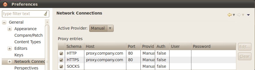
- In the Proxy Bypass section click Add Host...
- Add the IP address of target board (in place of xx.xx.xx.xx)
- Click OK.
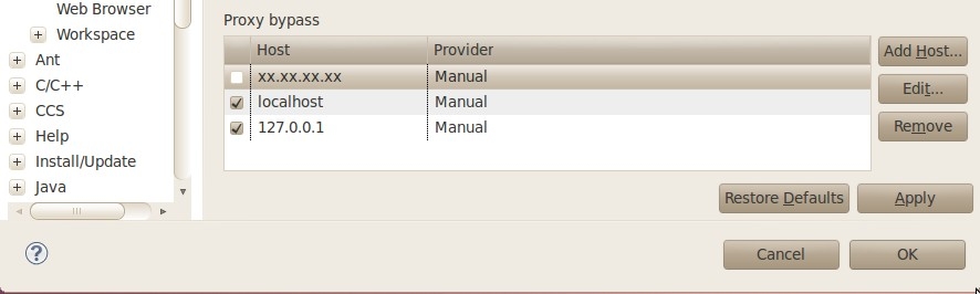
Connecting to the Target
After the New Connection Wizard has been completed and the Remote System Explorer view has been opened, the new connection must be configured to communicate with the target EVM.
- Right-Click the Target EVM node and select Connect
- A dialog like the one shown below will appear
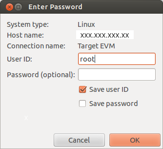
The Arago distribution that is used for our SDK is configured to use root as the usernamr and no password.
When prompted for a login use root for the user ID and leave the password blank. NOTE: you can save the user ID and password values to bypass this prompt in the future
The first time the target EVM file system is booted a private key and a public key is created in the target file system. Before connecting to the target EVM the first time, the public key must be exported from the target EVM to the Linux host system. To configure the key do
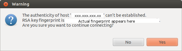
Click Yes to accept the key
Under certain circumstances a warning message can appear when the initial SSH connection is made as shown below. This could happen if the user deletes the target file system and replaces it with another target file system that has a different private RSA SSH key established (and the target board IP address remains the same). This is normal. In this case, click Yes and the public key from the target board will be exported to the Ubuntu host overwriting the existing public key.
At this point, all Remote System Explorer functions will be functional.
Target File System Access
Expand the Sftp Files -> Root node. The remote system file tree should now show the root directory. You can navigate anywhere in the remote file system down to the file level. Files can be dragged and dropped into the remote file tree. A context menu allows you to create, rename or delete files and folders.
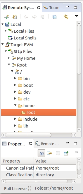
SSH Terminals
To open an SSH Terminal view
- Right-Click the Ssh Terminals node under the target EVM connection
- Select Launch Terminal from the context menu
- Type shell commands at the prompt in the terminal window. Below is a sample command to list the contents of the remote /usr folder.
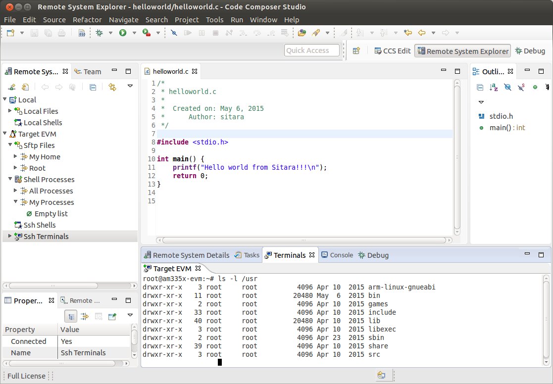
Next Steps
Debugging Source Code using Code Composer Studio
In order to debug user-space Linux code using Code Composer Studio v6, you first need to configure your project to use gdb and gdbserver included within the SDK.
Please refer to Debugging using GDB with Code Composer Studio for more information.
3.5.4.4. GDB Setup with CCS
Prerequisites
Before you configure RSE you should make sure the following prerequisites are met:
- Installed the Processor Linux SDK
- You have ran the SDK’s Setup Scripts
- Installed Code Composer Studio
- Created or imported a C/C++ Project. This project should be already open. For this guide a helloworld project will be used as an example.
- Connected your host PC and evm to the same network. Your PC and EVM should be on the same subnet.
- Remote System Explorer has already been setup and your connected to the board.
- The project you want to debug is already opened. Its important that the debug version of the executable is built.
Debugging using GDB and GDB Server
Creating the Debug Configuration for the Project
In CCS, select the project you wish to work with by clicking on it and highlighting it.
Select the Run -> Debug Configurations menu item. This opens a dialog box as shown below.
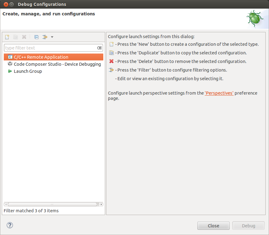
Double click C/C++ Remote Application. You should then see a new debug configuration named “helloworld Debug” as shown below.
Select your target connection from the Connection drop-down box. In the example the target connection is called My Target EVM.
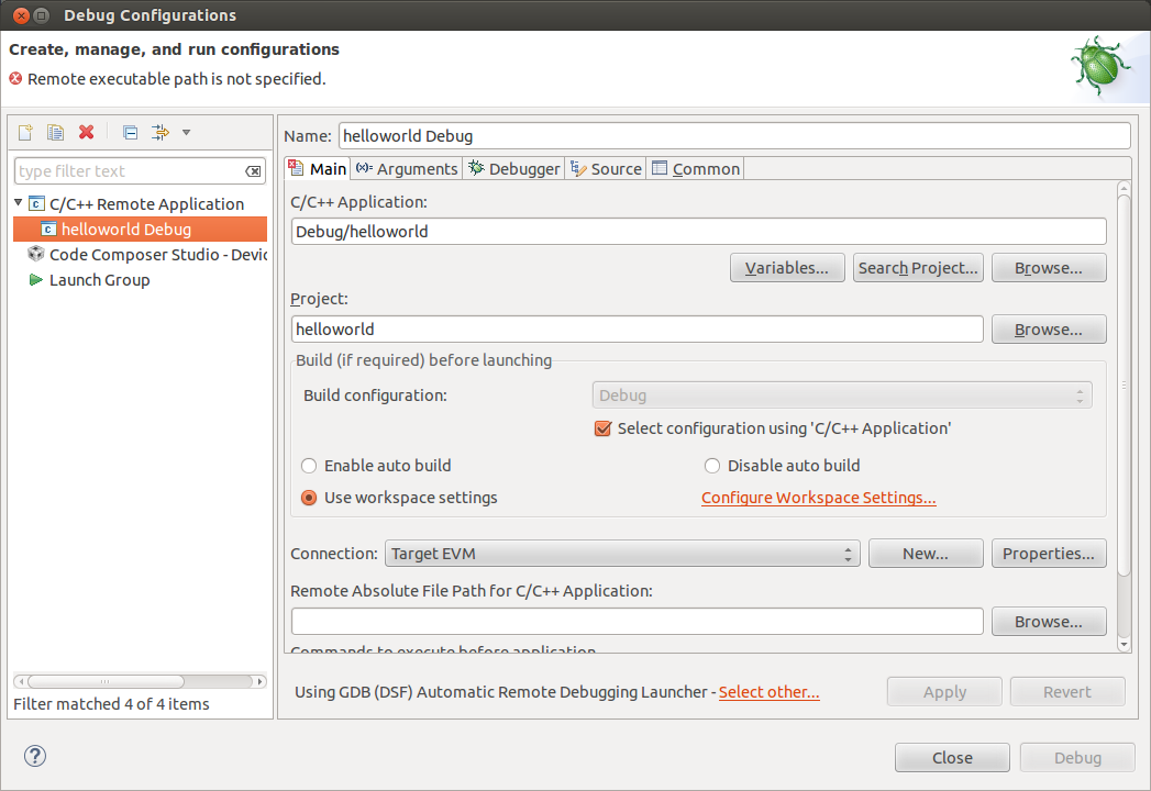
Click the Search Project button to open the Program Selection dialog box below. Click on the “armle - /helloworld/Debug/helloworld” item and click OK.
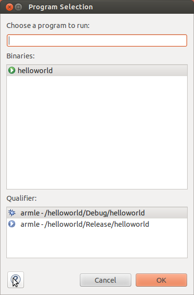
Click the “Browse...” button for “Remote Absolute File Path for C/C++ Application”. Navgate to the executable file on the remote file system. For this example, the executable file is found at ”/usr/bin/helloworld”.
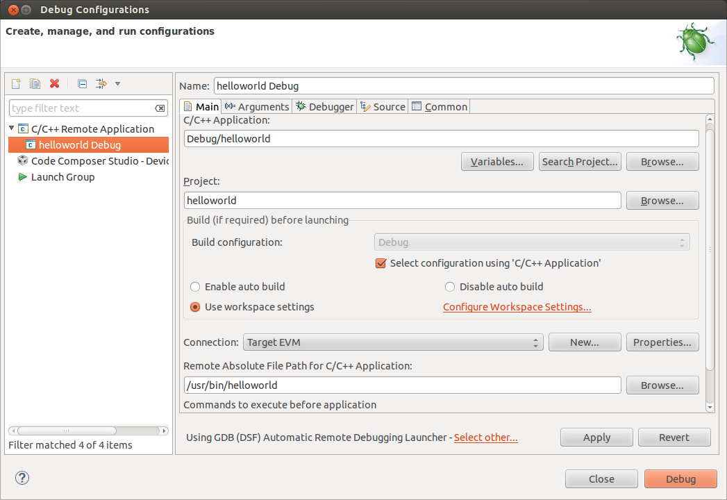
Click the Debugger tab. On the Debugger page, the Main tab should be selected.
Click Browse next to “GDB debugger” and browse to the GDB executable. GDB should be located at: <sdk-path>/linux-devkit/sysroot/i686-arago-linux/usr/bin/arm-linux-gnueabihf-gdb
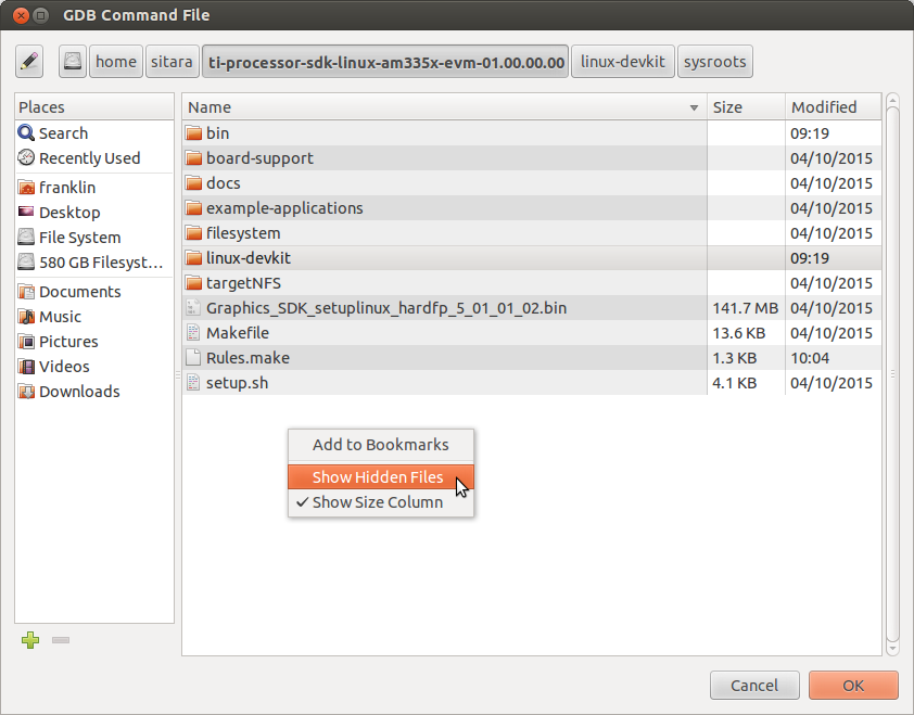
The .gdbinit file is used by GDB to locate source files and library files on the target. The .gdbinit file is created when the SDK environment script runs. Here is an example of a .gdbinit file.
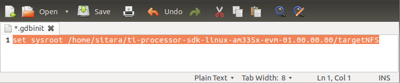
Click Ok button in the browse window and then click the Close button in the Debug Configuration window.
You are now ready to debug the application!
Running the Debug Session
- Make sure that you are setup for the debug build configuration which contains symbol information. In the C/C++ perspective, click on the helloworld project to select it and
Project -> Build Configurations -> Set Active -> Debug.
- 2. Click the green “bug” icon to build the executable, transfer the
- executable to the target, start gdbserver and and start debugging.
- CCS will change to the CCS Debug perspective. The debug tab will
show the running threads and their status. The source code window will show the program halted at the first executable source code line in the main() function. The Variables window will show the local variables and their current values.
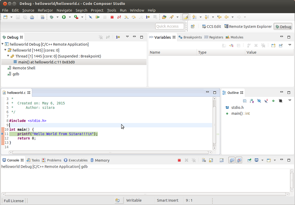
- To toggle a breakpoint, highlight the line of code in the source code window. Then click the Run -> Toggle Breakpoint menu item.
- Use the debugger “Step Over” and “Step Into” icons to step through the source code.
- To resume program execution, click the Run -> Resume menu item.
- NOTE: Do not click the Run -> Debug menu item, as that will attempt
- to start a new debug session.
- From here, you can make changes to the C source files, save the
- changes and then just click the green “Bug” icon again and you will be debugging the new executable on the target.
- (Each time you start the debugger the executable is built,
- automatically transferred to the target board and the gdbserver program is started for you.)
Stopping the Debug Session
When finished debugging the helloworld application, click the Run -> Resume menu item. To terminate the program, click the Terminate icon in CCS (this icon is a red square).
Manually Terminating Gdbserver
If the program being debugged ends abnormally or crashes CCS may be unable to automatically stop the application and or kill gdbserver. If this happens you may need to manually terminate gdbserver.
Note: These steps should only be followed if stop the application and gdbserver has failed when hitting the stop button discussed above.
Once setup, you can follow these steps to terminate gdbserver:
Change to the Remote System Explorer perspective. Right click on Shell Processes in the target connection tree and select Show in Table to open a Remote System Details window.
Double-click on “All Processes” in the table to display the list of processes runnning on the target system.
Click on “Executable Name” in the table headers to sort the list by executable name.
Find the gdbserver process. Right click on it and select Kill. This will open a “Send a Kill Signal” dialog box. Click the Kill button.
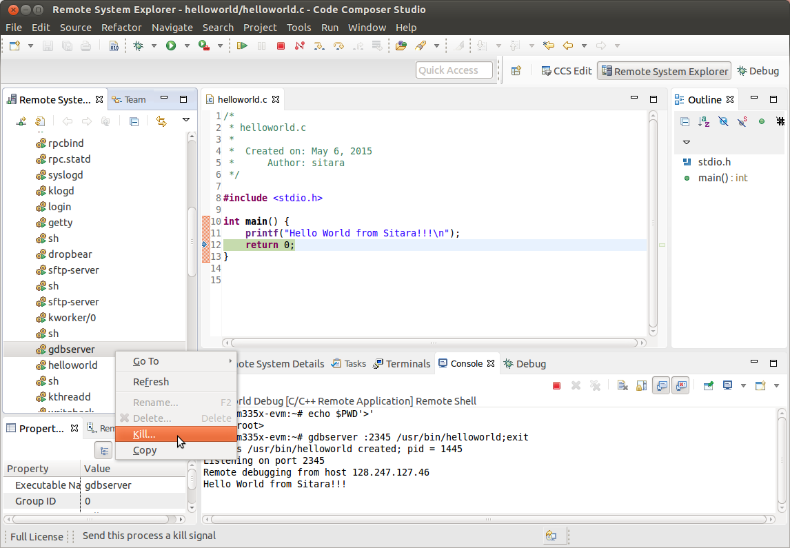
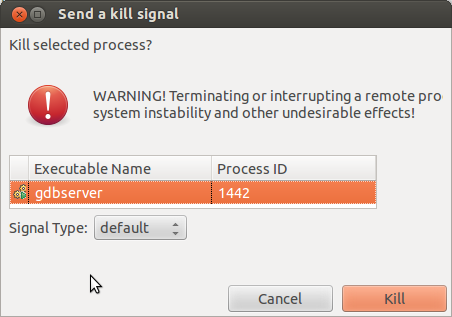
3.5.4.5. Kernel Debugging with CCS
Updated Toolchain
Starting with Sitara Linux SDK 6.0 the location of the toolchain has changed and for non ARM 9 devices a new Linaro based toolchain will be used. Details about the change in toolchain location can be found here. Also details about the switch to Linaro can be found here.
AM18x users are not affected by the switch to Linaro. Therefore, any references to the Linaro toolchain prefix “arm-linux-gnueabihf-” should be replaced with “arm-arago-linux-gnueabi-”.
Background
Linux Debug Overview
CCSv5 supports run mode debug (a.k.a. remote GDB debug, agent-based debug, application debug)and stop mode debug (a.k.a. JTAG debug, low-level debug). For Linux aware debug support (an extension of the stop mode debug), please read the section Linux Aware Debug below.
- In run mode debug, the user can debug one or more Linux processes. On the host side, CCSv5 launches a cross platform GDB debugger to control the target side agent (a GDB server process). The GDB server launches or attaches to the process to be debugged and accepts instructions from the host side over a serial or TCP/IP connection. The Linux kernel remains active during the debug session. The user can only examine the state of the processes being debugged.
- In the stop mode debug, CCSv5 halts the target using a JTAG emulator. The Linux kernel and all processes are suspended completely. The user can examine the state of the target and the execution state of the current process.
IMPORTANT! This page refers to CCS version 6.0.0 and newer.
Run Mode Debug
Dependencies
The following dependencies apply to Run Mode Debug:
CCS versions: CCSv5.3 or greater
Devices: any core that is capable of running Linux: Cortex-A, ARM9, C66x.
Host requirement: a cross platform GDB debugger (typically part of a GCC package like CodeSourcery or Arago)
Target requirement: a GDB server that is compatible with the GDB debugger located on the host (typically part of a SDK package like EZSDK, DVSDK, etc.)
A GCC project (see How to create GCC projects in CCSv5).
The run mode debug requires two connections to the target system: 1. One connection to the target console is used to execute Linux commands.
If using a serial port (common in all TI’s EVMs and low-cost boards like Beagleboard and Pandaboard), this connection can be done using a simple terminal program like Hyperterminal, Putty, TeraTerm or even a CCSv5 terminal plug-in.
If using Ethernet, this connection must be done using one of the programs above and configuring it for telnet or SSH. Keep in mind that the linux running on the target board requires a telnet or SSH server running on it.
2. The other connection is used by the gdb debugger to communicate with the gdb server running on the target.
This connection can be done either via Ethernet or serial port. Keep in mind the speed of a serial connection can be a lot slower and timeouts may occur.
Procedure
IMPORTANT! In certain versions CCSv5 does not enable “CDT GDB Debugging” configurations. You need to enable them from the Capabilities tab in the Preference dialog (select Window –> Preferences –> General –> Capabilities).
Bring up the Debug Configurations dialog by selecting menu Run –> Debug Configurations
Select C/C++ Remote Application
Click on the icon New launch configuration (Top left of the pane)
Set the fields C/C++ Application: andProject: respectively to the existing project in the workspace and the binary executable file
Note: If the project is already in focus (Active or highlighted) in the Project Explorer view, these fields will be already populated.
In tab Main, click on the link Select Other at the bottom where it says Using GDB (ASF) Automatic Remote Debugging Launcher. Check Use configuration specific settings and select GDB (DSF) Manual Remote Degugging Launcher. Click OK.
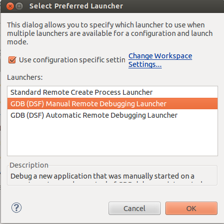
Note: It is possible to set up CCSv5 to automatically connect and launch the debugger in the target by leaving the settings above untouched. Check section 8 of the Eclipse CDT FAQ.
Note: Other options like Enable auto build, arguments and others can be modified at this time.
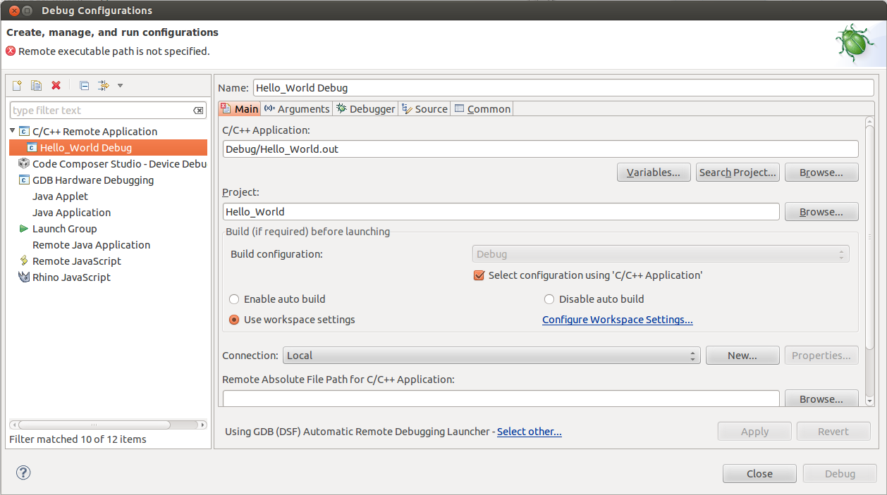
Select the Debugger tab and specify the GDB debugger as well as the GDB command file. In this case the GDB debugger from Arago is being used, but it is possible to use also CodeSourcery or other toolchain.
- Click browse next to “GDB command file” and browse to the .gdbinit
- file in the SDK install directory. When you try to browse to the .gdbinit file, you will need
- to R-Click -> Show Hidden Files to see the file. Click the Close
button and you are now ready to debug the application!
- In this example of the 06.00.00.00 SDK, the path is: /home/user/AM335X/SDK/ti-sdk-am335x-evm-06.00.00.00/linux-devkit/sysroot/i686-arago-linux/usr/bin/arm-linux-gnueabihf-gdb
- The GDB init file is located: /home/user/AM335X/SDK/ti-sdk-am335x-evm-06.00.00.00/.gdbinit
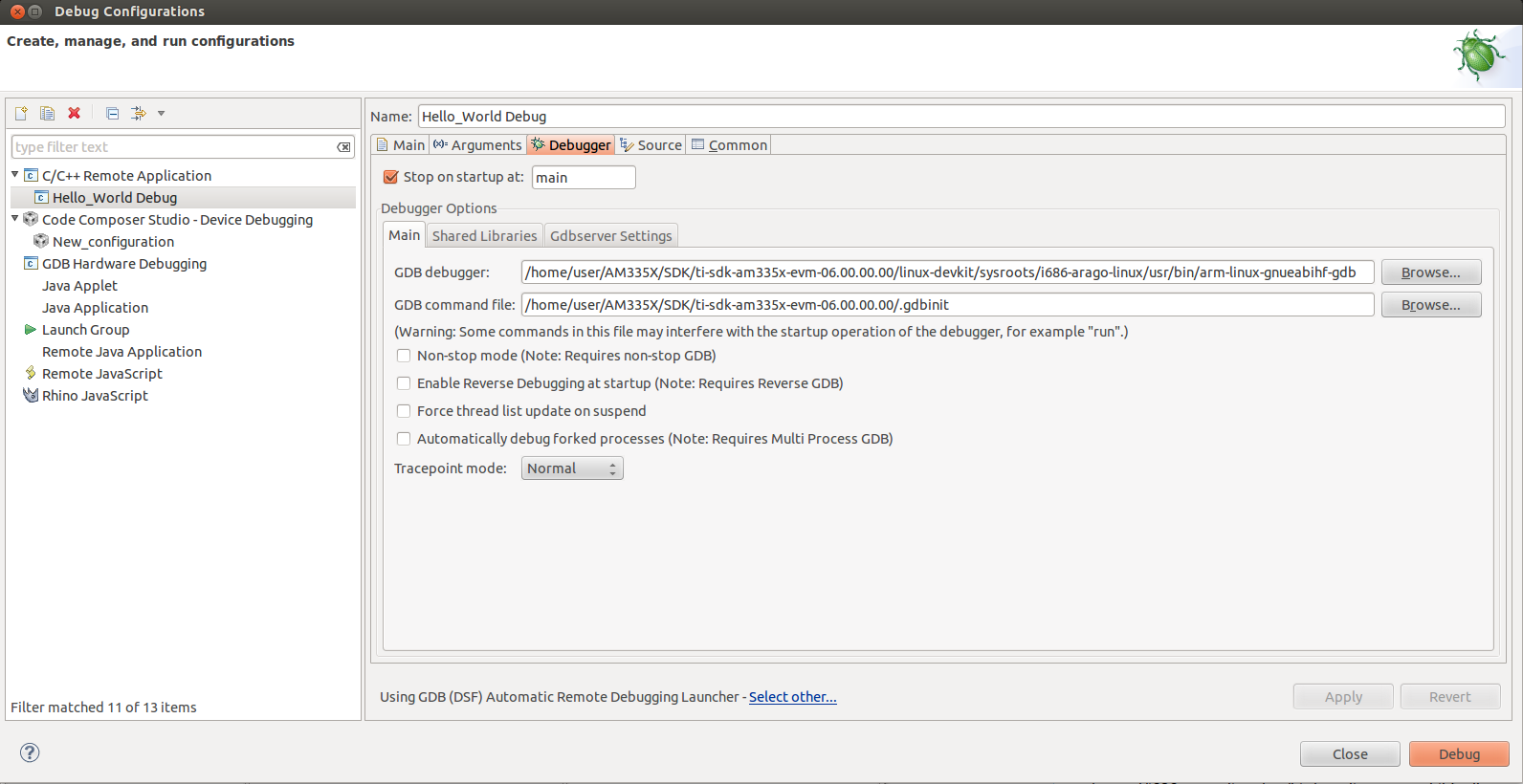
On the Debugger Connection tab, specify the IP address and port of the GDB server running on the target.
Note: the port number is arbitrary and is specified when the gdbserver is launched - unless you have a strong reason to change it, the value of 10000 is just fine.
Note: the IP address of the target can be determined from the target linux console.
IMPORTANT! Some SDKs do not have gdbserver installed by default in the supplied filesystem. Check the SDK documentation for details on how to install it.
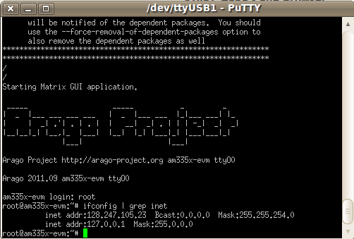
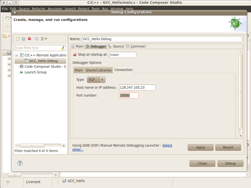
On the target console, start the GDB server specifying the application file and the port number.
Note: make sure the port number matches the one specified in the Debugger Connection tab (10000 by default).
Note: the application under debug must be located on the target filesystem. This can be done in multiple ways: either copying it to the shared NFS directory, to the SD card being used to boot linux, etc.
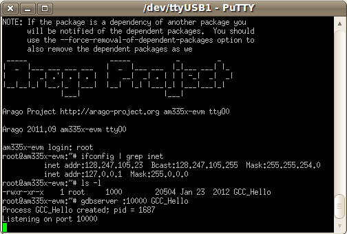
Launch the debug configuration by clicking the Debug button.
- CCSv5 will launch the GDB debugger to connect to the GDB server.
- After the connection is established, you can step, set breakpoints and view the memory, registers and variables of the application process running on the target.
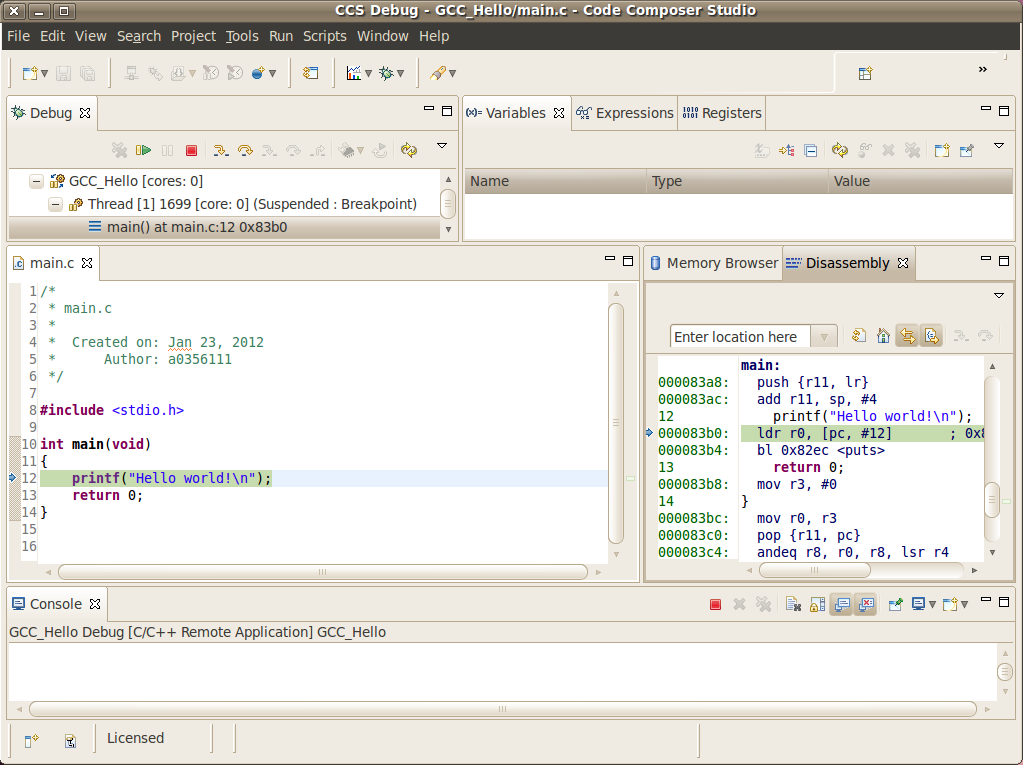
You may need to set the shared library (object) search path in a cross compile debug enviroment.
- Under Debug Configuration -> Debugger tab -> Shared Libraries tab enter the path to the target filesystem lib directory
- You may need a copy of the target filesystem on the local debug host
Stop Mode Debug
Dependencies
- CCS version 5.3.0 or greater. This facilitates working on either a Windows host, or a Linux host.
In addition to the procedure below, a short video clip is located here.
- Devices: any core that is capable of running Linux: Cortex-A, ARM9, C66x.
- Host system requirements:
- Target system requirements: a Linux distribution running on the target. Kernel releases 2.6.x and 3.1.x were tested.
Procedure
Compiling the Linux kernel with debug information
- Enable Kernel hacking –> Compile the kernel with debug info
Also, if the kernel is in experimental mode, you should enable the option below:
- Kernel hacking —> Enable stack unwinding support
To check if the kernel is in this mode, check if the option below is enabled.
- General Setup —> Prompt for development and/or incomplete code/drivers
Note: for kernel 3.1.0 and above, there is an additional option that must be set:
- Kernel Hacking —> Enable JTAG clock for debugger connectivity
Note: for kernel 3.2.0, the option Enable stack unwinding support shown above is only available if the kernel is built with ARM EABI support. To enable it, go to:
- Kernel Features —> Use the ARM EABI to compile the kernel
Note: for kernel 3.2.0, the option Compile the kernel with debug info shown above is only available if the option Kernel Debugging is enabled. To do it, go to:
- Kernel hacking —> Kernel Debugging
Creating a source code project for the kernel
Create a new C/C++ project by selecting File –> New –> Project and select Makefile Project with Existing Code. Click Next.
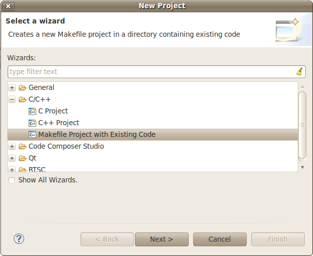
In the section Existing Code Location, click on Browse... and point to the root directory of the Linux kernel source tree. Leave the toolchain as <none> and click Finish.
To prevent CCS from building the Linux kernel automatically before launching the debugger, this option must be disabled. Highlight the Linux kernel project in the Project Explorer view, right click and select Build Options..., then select C/C++ Build in the left tree and the tab Behaviour. Uncheck all the build rules boxes and click OK.
Note: it is possible the C-syntax error checker built into Eclipse is also activated, which may throw errors while launching the debugger. It can be configured by right-clicking on the project –> Build Options... –> click on Show Advanced Settings –> C/C++ General –> Code Analysis. It can also be completely disabled by going to the submenu Launching and then unchecking the box Run as you type (selected checkers). |
Associating the Kernel Project with the Target
At this point, a target configuration file (.ccxml) that corresponds to your emulator and board must be ready.
In this example a Beaglebone (AM3359) was used, together with the Sitara support package available at the CCS download page. Note: check the Getting Started Guide to learn how to create one. Important! When debugging a target running any High-level OS (Linux, WinCE, Android, etc.) or its support/initialization routines (u-boot, WinCE bootloader, etc.) you should not rely on GEL files in the target configuration (.ccxml) for device and peripheral initializations that will disrupt your environment. Details on how to add/remove GEL files are shown in the section Advanced target configurations –> Adding GEL files to a target configuration of the CCSv5 Getting Started Guide.
Select menu Run –> Debug Configurations
Select Code Composer Studio - Device Debugging and click on the button New Launch configuration at the top left.
Click on the button File System... near the box Target Configuration to select the target configuration file (.ccxml) for your hardware.
Optional: give a meaningful name for the Debug Configuration at the box Name:
Optional: depending on the target configuration, at this point a list of cores will be shown and can be disabled to improve the debugger performance.
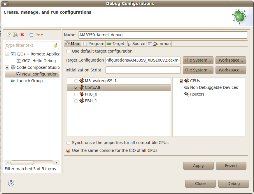
Select the tab Program to assign the Linux kernel source code to the Debug configuration.
On the drop-down menu Device select the core where the Linux is running. In this example the core Texas Instruments XDS100v2 USB Emulator_0/CortxA8 was selected
Click on the button Workspace... near the box Project to select the Linux kernel project
- In this example it was used the project linux-3.1.0-psp04.06.00.03.sdk
- For the latest version, use /home/user/AM335X/SDK/ti-sdk-am335x-evm-06.00.00.00/board-support/linux-3.2.0-psp04.06.00.11
Click on the button File System... near the box Program to select the EABI executable vmlinux that contains the debug symbols
Note:If the Linux kernel was rebuilt, the location of this file is usually in the main directory of the Linux kernel source tree. /home/nick/AM335X/SDK/ti-sdk-am335x-evm-06.00.00.00/board-support/linux-3.2.0-psp04.06.00.11
Important! It is common that a file vmlinux is also provided in the boot partition of the SD card shipped with the development board (where the file uImage is also located). However, check its size; if it is relatively small when compared to uImage (3, 4 times larger) it is possible it does not carry debug information. A typical size for the vmlinux file usually starts at 30~40MB.
At last, check the box Load symbols only. Click Apply.
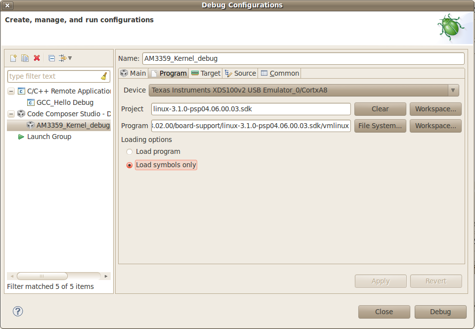
Now the debug session is ready to be launched. At this point, the emulator must be connected, the target board powered up and Linux running (typically in the command prompt). Click on the Debug button.
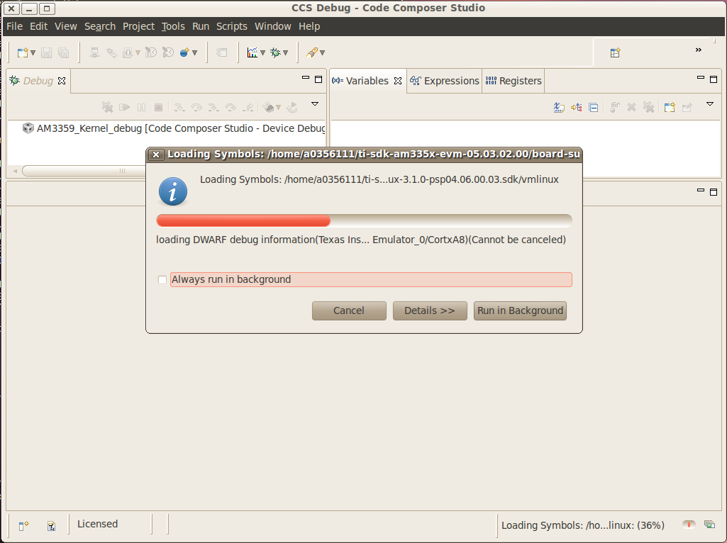
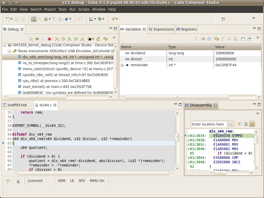
Mixed Mode Debug
The stop mode debug can be used concurrently with the run mode debug. The user can set breakpoints in the user process using the run mode debug and breakpoints in the kernel using the stop mode debug. To demonstrate this, a call to the function sleep() is added to the Linux application used earlier in the Run mode debug and a breakpoint is added to the function sys_nanosleep() (file <kernel/hrtimer.c>). This will provoke a halt on the breakpoint set in the Stop Mode debug caused by a function call from the Linux application in the Run mode. 1. Search for the function call hrtimer_nanosleep() on the file <kernel/hrtimer.c> that belongs to the Linux kernel project. 2. With the Stop mode debug session still running, halt the target. Right-click on the line of the call, select Breakpoint (Code Composer Studio) then Hardware Breakpoint. Resume the target execution. 3. Start a Run mode debug session with the application that has the sleep() function call. After launching, the Debug view should show two debug sessions as in the screen below:
4. Put the target to run. When the application calls sleep() the Stop mode debug session should halt at the breakpoint, as shown in the screen below:
Important! Keep in mind that halting the Linux kernel while GDB/GDBserver are running may cause communication timeouts, clock skews or other glitches inherent from the fact that the host system and other peripherals are still running. |
Linux Aware Debug
Limitations and Known Issues
1. When performing Run Mode debug, by default Eclipse looks in the host PC root directory for runtime shared libraries, thus failing to load these when debugging the application in the target hardware. The error messages are something like:
warning: .dynamic section for “/usr/lib/libstdc++.so.6” is not at the expected address (wrong library or version mismatch?) warning: .dynamic section for “/lib/libm.so.6” is not at the expected address (wrong library or version mismatch?) warning: .dynamic section for “/lib/libgcc_s.so.1” is not at the expected address (wrong library or version mismatch?) warning: .dynamic section for “/lib/libc.so.6” is not at the expected address (wrong library or version mismatch?) When SDKs setup.sh script, it should automatically generate a .gdbinit file for you in the base directory of the SDK.
The file will contain the line: set sysroot <SDK-PATH>/targetNFS.
An example would be
I
3.6. IPC
3.6.1. Overview
Overview
Getting Started
| Links | Description |
|---|---|
| Multiple Ways of ARM/DSP Communication | Provides brief overview of each method and pros and cons |
| IPC Quick Start Guide | Building and setting up examples for IPC with Processor SDK |
Technical Documents
| Links | Description |
|---|---|
| IPC User’s Guide | TI IPC User’s Guide |
Starting IPC project
| Links | Description |
|---|---|
| Linux IPC on AM57xx | General info on IPC under Linux environment for AM57xx |
| Running IPC example on DRA7xx/AM572x | Info on running RTOS IPC examples on DRA7xx/AM572x |
| Training video on how to Run IPC example on AM572x | Step-by-step Video on running the IPC examples under Linux environment on AM572x |
| AM57x Customizing Multicore Application | Info and guide to customize memory usage for custom design based on AM57x |
| Modifying Memory Usage For IPUMM using DRA7xx | Info on modifying memory usage of IPU for DRA7xx |
3.6.2. IPC Quick Start Guide
Overview
This wiki page is meant to be a Quick Start Guide for applications using IPC (Inter Processor Communication) in Processor SDK.
It begins with details about the out-of-box demo provided in the Processor SDK Linux filesystem, followed by rebuilding the demo code and running the built images. ( This covers the use case with the Host running linux OS and the slave cores running RTOS).
Also details about building and running the IPC examples are covered.
The goal is to provides information for users to get familiar with IPC and its build environment, in turn, to help users in developing their projects quickly.
Linux out of box demos
The out of box demo is only available on Keystone-2 EVMs.
Note
This assumes the release images are loaded in the flash/SD Card. If needed to update to latest release follow the https://processors.wiki.ti.com/index.php/Processor_SDK_Linux_Getting_Started_Guide to update the release images on flash memory/SD card on the EVM using Program-evm or using the procedures for SD Card.
Connect the EVM Ethernet port 0 to a corporate or local network with DHCP server running, when the Linux kernel boots up, the rootfs start up scripts will get an IP address from the DHCP server and print the IP address to the EVM on-board LCD.
Open an Internet browser (e.g. Mozilla Firefox) on a remote computer that connects with the same network as the EVM.
Type the IP address displayed on EVM LCD to the browser and click cancel button to launch the Matrix launcher in the remote access mode instead of on the on-board display device.
Click the Multi-core Demonstrations, then Multi-core IPC Demo to start the IPC demonstration.
The result from running IPC Demo
Note
To view the out-of-box demo source code, please install Linux and RTOS Processor SDKs from SDK download page
The source code are located in:
Linux side application: <RTOS_SDK_INSTALL_DIR>/ipc_x_xx_xx_xx/linux/src/tests/MessageQBench.c
DSP side application: <RTOS_SDK_INSTALL_DIR>/ipc_x_xx_xx_xx/packages/ti/ipc/tests/messageq_single.c
Rebuilding the demo:
1. Install Linux Proc SDK at the default location
2. Include cross-compiler directory in the $PATH
export PATH=<sdk path>/linux-devkit/sysroots/x86_64-arago-linux/usr/bin:$PATH
3. Setup TI RTOS PATH using
export TI_RTOS_PATH=<RTOS_SDK_INSTALL_DIR>
export IPC_INSTALL_PATH=<RTOS_SDK_IPC_DIR>
4. In Linux Proc SDK, start the top level build:
$ make ti-ipc-linux
- 5. The ARM binary will be located under the directory where the
- source code is <RTOS_SDK_INSTALL_DIR>/ipc_x_xx_xx_xx/linux/src/tests/
Note
Please follow the build instruction in Linux Kernel User Guide to set up the build environment.
1. Install RTOS Proc SDK at the default location
- 2. If RTOS Proc SDK and tools are not installed at its default
- location, then the environment variables, SDK_INSTALL_PATH and TOOLS_INSTALL_PATH need to be exported with their installed locations.
export SDK_INSTALL_PATH=<RTOS_SDK_INSTALL_DIR>
export TOOLS_INSTALL_PATH=<RTOS_SDK_INSTALL_DIR>
Note
For ProcSDK 3.2 or older releases, tools are not included in RTOS SDK, so point to CCS:
export TOOLS_INSTALL_PATH=<TI_CCS_INSTALL_DIR>
- 3. Configure the build environment in
- <RTOS_SDK_INSTALL_DIR>/processor_sdk_rtos_<platform>_x_xx_xx_xx directory
$ cd <RTOS_SDK_INSTALL_DIR>/processor_sdk_rtos_<platform>_x_xx_xx_xx
$ source ./setupenv.sh
4. Start the top level build:
$ make ipc_bios
- 5. The DSP binary will be located under the directory where the
- source code is
<RTOS_SDK_INSTALL_DIR>/ipc_x_xx_xx_xx/packages/ti/ipc/tests
Build IPC Linux examples
IPC package and its examples are delivered in RTOS Processor SDK, but can be built from Linux Proc SDK. To build IPC examples, both Linux and RTOS processor SDKs need to be installed. They can be downloaded from SDK download page
To install Linux Proc SDK, please follow the instruction in Linux SDK Getting Started Guide
To Install RTOS Proc SDK, please follow the instructions in RTOS SDK Getting Started Guide
Once the Linux and RTOS Processor SDKs are installed at their default locations, the IPC Linux library, not included in the Linux Proc SDK, can be built on Linux host machine with the following commands:
$ cd <TI_LINUX_PROC_SDK_INSTALL_DIR>
$ make ti-ipc-linux
The IPC examples in RTOS Proc SDK including out-of-box demo can be built with the following commands:
$ cd <TI_LINUX_PROC_SDK_INSTALL_DIR>
$ make ti-ipc-linux-examples
Note
Please follow the build instruction in Linux Kernel User Guide to set up the build environment.
Note
If RTOS Proc SDK is not installed at its default location, then the environment variables, TI_RTOS_PATH needs to be exported with their installed locations.
export TI_RTOS_PATH=<TI_RTOS_PROC_SDK_INSTALL_DIR>
Also if using Processor SDK 3.2 or older release, need to also set TI_CCS_PATH to CCSV6 location
export TI_CCS_PATH=<TI_CCS_INSTALL_DIR>/ccsv6
Run IPC Linux examples
- The executables are in RTOS Proc SDK under the ipc_xx_xx_xx_xx/examples directory.
<device>_<OS>_elf/ex<xx_yyyy>/host/bin/debug/app_host
<device>_<OS>_elf/ex<xx_yyyyyy/<processor_or_component>/bin/debug/<ServerCore_or_component.xe66 for DSP
<device>_<OS>_elf/ex<xx_yyyyyy/<processor_or_component>/bin/debug/<sServerCore_or_component.xem4 for IPU
- Copy the executables to the target filesystem. It can also be done by running “make ti-ipc-linux-examples_install” to install the binaries to DESTDIR if using NFS filesystem. ( See Moving_Files_to_the_Target_System for details of moving files to filesystem)
- Load and start the executable on the target DSP/IPU.
For AM57x platforms, Modify the symbolic links in /lib/firmware of the default image names to the built binaries. The images pointed by the symbolic links will be downloaded to and started execution on the corresponding processors by remoteproc during Linux Kernel boots.
DSP image files: dra7-dsp1-fw.xe66 dra7-dsp2-fw.xe66
IPU image files: dra7-ipu1-fw.xem4 dra7-ipu2-fw.xem4
For OMAP-L138 platform, Modify the symblic link in /lib/firmware of the default image names to the build binary
DSP image files: rproc-dsp-fw
For Keystone-2 platforms, use the Multi-Processor Manager (MPM) Command Line utilities to download and start the DSP executibles. Please refer to /usr/bin/mc_demo_ipc.sh for examples
The available commands are:
mpmcl reset <dsp core>
mpmcl status <dsp core>
mpmcl load <dsp core>
mpmcl run <dsp core>
- Run the example From the Linux kernel prompt, run the host executable, app_host. An example from running ex02_messageq:
root@am57xx-evm:~# ./app_host DSP1
The console output:
--> main:
--> Main_main:
--> App_create:
App_create: Host is ready
<-- App_create:
--> App_exec:
App_exec: sending message 1
App_exec: sending message 2
App_exec: sending message 3
App_exec: message received, sending message 4
App_exec: message received, sending message 5
App_exec: message received, sending message 6
App_exec: message received, sending message 7
App_exec: message received, sending message 8
App_exec: message received, sending message 9
App_exec: message received, sending message 10
App_exec: message received, sending message 11
App_exec: message received, sending message 12
App_exec: message received, sending message 13
App_exec: message received, sending message 14
App_exec: message received, sending message 15
App_exec : message received
App_exec: message received
App_exec: message received
<-- App_exec: 0
--> App_delete:
<-- App_delete:
<-- Main_main:
<-- main:
root@am57xx-evm:~#
Build IPC RTOS examples
The IPC package also includes examples for the use case with Host and the slave cores running RTOS/BIOS. They can be built from the Processor SDK RTOS package.
Note
To Install RTOS Proc SDK, please follow the instructions in RTOS SDK Getting Started Guide In the RTOS Processor SDK, the ipc examples are located under <RTOS_SDK_INSTALL_DIR>/processor_sdk_rtos_<platform>_x_xx_xx_xx/ipc_<version>/examples/<platform>_bios_elf.
NOTE: The platform in the directory name may be slightly different from the top level platform name. For example, platform name DRA7XX refer to common examples for DRA7XX & AM57x family of processors.
Once the RTOS Processor SDKs is installed at the default location, the IPC examples can be built with the following commands:
1. Configure the build environment in
<RTOS_SDK_INSTALL_DIR>/processor_sdk_rtos_<platform>_x_xx_xx_xx directory
$ cd <RTOS_SDK_INSTALL_DIR>/processor_sdk_rtos_<platform>_x_xx_xx_xx
$ source ./setupenv.sh
2. Start the top level build:
$ make ipc_examples
Note
If RTOS Proc SDK and tools are not installed at its default location, then the environment variables, SDK_INSTALL_PATH and TOOLS_INSTALL_PATH need to be exported with their installed locations.
Run IPC RTOS examples
The binary images for the examples are located in the corresponding directories for host and the individual cores. The examples can be run by loading and running the binaries using CCS through JTAG.
Build your own project
After exercising the IPC build and running examples, users can take further look at the source code of the examples as references for their own project.
The sources for examples are under ipc_xx_xx_xx_xx/examples/<device>_<OS>_elf directories. Once modified the same build process described above can be used to rebuild the examples.
3.6.3. IPC for AM57xx
Introduction
This article is geared toward AM57xx users that are running Linux on the Cortex A15. The goal is to help users understand how to gain entitlement to the DSP (c66x) and IPU (Cortex M4) subsystems of the AM57xx.
AM572x device has two IPU subsystems (IPUSS), each of which has 2 cores. IPU2 is used as a controller in multi-media applications, so if you have Processor SDK Linux running, chances are that IPU2 already has firmware loaded. However, IPU1 is open for general purpose programming to offload the ARM tasks.
There are many facets to this task: building, loading, debugging, MMUs, memory sharing, etc. This article intends to take incremental steps toward understanding all of those pieces.
Software Dependencies to Get Started
Prerequisites
- Processor SDK Linux for AM57xx (Version 3.01 or newer needed)
- Processor SDK RTOS for AM57xx
- Code Composer Studio (choose version as specified on Proc SDK download page)
Note
Please be sure that you have the same version number for both Processor SDK RTOS and Linux.
For reference within the context of this wiki page, the Linux SDK is installed at the following location:
/mnt/data/user/ti-processor-sdk-linux-am57xx-evm-xx.xx.xx.xx
├── bin
├── board-support
├── docs
├── example-applications
├── filesystem
├── ipc-build.txt
├── linux-devkit
├── Makefile
├── Rules.make
└── setup.sh
The RTOS SDK is installed at:
/mnt/data/user/my_custom_install_sdk_rtos_am57xx_xx.xx
├── bios_6_xx_xx_xx
├── cg_xml
├── ctoolslib_x_x_x_x
├── dsplib_c66x_x_x_x_x
├── edma3_lld_2_xx_xx_xx
├── framework_components_x_xx_xx_xx
├── imglib_c66x_x_x_x_x
├── ipc_3_xx_xx_xx
├── mathlib_c66x_3_x_x_x
├── ndk_2_xx_xx_xx
├── opencl_rtos_am57xx_01_01_xx_xx
├── openmp_dsp_am57xx_2_04_xx_xx
├── pdk_am57xx_x_x_x
├── processor_sdk_rtos_am57xx_x_xx_xx_xx
├── uia_2_xx_xx_xx
├── xdais_7_xx_xx_xx
CCS is installed at:
/mnt/data/user/ti/my_custom_ccs_x.x.x_install
├── ccsvX
│ ├── ccs_base
│ ├── doc
│ ├── eclipse
│ ├── install_info
│ ├── install_logs
│ ├── install_scripts
│ ├── tools
│ ├── uninstall_ccs
│ ├── uninstall_ccs.dat
│ ├── uninstallers
│ └── utils
├── Code Composer Studio x.x.x.desktop
└── xdctools_x_xx_xx_xx_core
├── bin
├── config.jar
├── docs
├── eclipse
├── etc
├── gmake
├── include
├── package
├── packages
├── package.xdc
├── tconfini.tcf
├── xdc
├── xdctools_3_xx_xx_xx_manifest.html
├── xdctools_3_xx_xx_xx_release_notes.html
├── xs
└── xs.x86U
Typical Boot Flow on AM572x for ARM Linux users
AM57xx SOC’s have multiple processor cores - Cortex A15, C66x DSP’s and ARM M4 cores. The A15 typically runs a HLOS like Linux/QNX/Android and the remotecores(DSP’s and M4’s) run a RTOS. In the normal operation, boot loader(U-Boot/SPL) boots and loads the A15 with the HLOS. The A15 boots the DSP and the M4 cores.
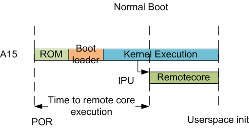
In this sequence, the interval between the Power on Reset and the remotecores (i.e. the DSP’s and the M4’s) executing is dependent on the HLOS initialization time.
Getting Started with IPC Linux Examples
The figure below illustrates how remoteproc/rpmsg driver from ARM Linux kernel communicates with IPC driver on slave processor (e.g. DSP, IPU, etc) running RTOS.
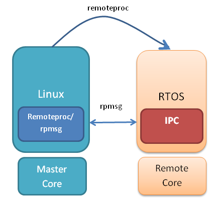
In order to setup IPC on slave cores, we provide some pre-built examples in IPC package that can be run from ARM Linux. The subsequent sections describe how to build and run this examples and use that as a starting point for this effort.
Building the Bundled IPC Examples
The instructions to build IPC examples found under ipc_3_xx_xx_xx/examples/DRA7XX_linux_elf have been provided in the `Processor_SDK IPC Quick Start Guide <https://processors.wiki.ti.com/index.php/Processor_SDK_IPC_Quick_Start_Guide#Build_IPC_Linux_examples>`__.
Let’s focus on one example in particular, ex02_messageq, which is located at <rtos-sdk-install-dir>/ipc_3_xx_xx_xx/examples/DRA7XX_linux_elf/ex02_messageq. Here are the key files that you should see after a successful build:
├── dsp1
│ └── bin
│ ├── debug
│ │ └── server_dsp1.xe66
│ └── release
│ └── server_dsp1.xe66
├── dsp2
│ └── bin
│ ├── debug
│ │ └── server_dsp2.xe66
│ └── release
│ └── server_dsp2.xe66
├── host
│ ├── debug
│ │ └── app_host
│ └── release
│ └── app_host
├── ipu1
│ └── bin
│ ├── debug
│ │ └── server_ipu1.xem4
│ └── release
│ └── server_ipu1.xem4
└── ipu2
└── bin
├── debug
│ └── server_ipu2.xem4
└── release
└── server_ipu2.xem4
Running the Bundled IPC Examples
On the target, let’s create a directory called ipc-starter:
root@am57xx-evm:~# mkdir -p /home/root/ipc-starter
root@am57xx-evm:~# cd /home/root/ipc-starter/
You will need to copy the ex02_messageq directory of your host PC to that directory on the target (through SD card, NFS export, SCP, etc.). You can copy the entire directory, though we’re primarily interested in these files:
- dsp1/bin/debug/server_dsp1.xe66
- dsp2/bin/debug/server_dsp2.xe66
- host/bin/debug/app_host
- ipu1/bin/debug/server_ipu1.xem4
- ipu2/bin/debug/server_ipu2.xem4
The remoteproc driver is hard-coded to look for specific files when loading the DSP/M4. Here are the files it looks for:
- /lib/firmware/dra7-dsp1-fw.xe66
- /lib/firmware/dra7-dsp2-fw.xe66
- /lib/firmware/dra7-ipu1-fw.xem4
- /lib/firmware/dra7-ipu2-fw.xem4
These are generally a soft link to the intended executable. So for example, let’s update the DSP1 executable on the target:
root@am57xx-evm:~# cd /lib/firmware/
root@am57xx-evm:/lib/firmware# rm dra7-dsp1-fw.xe66
root@am57xx-evm:/lib/firmware# ln -s /home/root/ipc-starter/ex02_messageq/dsp1/bin/debug/server_dsp1.xe66 dra7-dsp1-fw.xe66
To reload DSP1 with this new executable, we perform the following steps:
root@am57xx-evm:/lib/firmware# cd /sys/bus/platform/drivers/omap-rproc/
root@am57xx-evm:/sys/bus/platform/drivers/omap-rproc# echo 40800000.dsp > unbind
[27639.985631] omap_hwmod: mmu0_dsp1: _wait_target_disable failed
[27639.991534] omap-iommu 40d01000.mmu: 40d01000.mmu: version 3.0
[27639.997610] omap-iommu 40d02000.mmu: 40d02000.mmu: version 3.0
[27640.017557] omap_hwmod: mmu1_dsp1: _wait_target_disable failed
[27640.030571] omap_hwmod: mmu0_dsp1: _wait_target_disable failed
[27640.036605] remoteproc2: stopped remote processor 40800000.dsp
[27640.042805] remoteproc2: releasing 40800000.dsp
root@am57xx-evm:/sys/bus/platform/drivers/omap-rproc# echo 40800000.dsp > bind
[27645.958613] omap-rproc 40800000.dsp: assigned reserved memory node dsp1_cma@99000000
[27645.966452] remoteproc2: 40800000.dsp is available
[27645.971410] remoteproc2: Note: remoteproc is still under development and considered experimental.
[27645.980536] remoteproc2: THE BINARY FORMAT IS NOT YET FINALIZED, and backward compatibility isn't yet guaranteed.
root@am57xx-evm:/sys/bus/platform/drivers/omap-rproc# [27646.008171] remoteproc2: powering up 40800000.dsp
[27646.013038] remoteproc2: Booting fw image dra7-dsp1-fw.xe66, size 4706800
[27646.028920] omap_hwmod: mmu0_dsp1: _wait_target_disable failed
[27646.034819] omap-iommu 40d01000.mmu: 40d01000.mmu: version 3.0
[27646.040772] omap-iommu 40d02000.mmu: 40d02000.mmu: version 3.0
[27646.058323] remoteproc2: remote processor 40800000.dsp is now up
[27646.064772] virtio_rpmsg_bus virtio2: rpmsg host is online
[27646.072271] remoteproc2: registered virtio2 (type 7)
[27646.078026] virtio_rpmsg_bus virtio2: creating channel rpmsg-proto addr 0x3d
More info related to loading firmware to the various cores can be found here.
Finally, we can run the example on DSP1:
root@am57xx-evm:/sys/bus/platform/drivers/omap-rproc# cd /home/root/ipc-starter/ex02_messageq/host/bin/debug
root@am57xx-evm:~/ipc-starter/ex02_messageq/host/bin/debug# ./app_host DSP1
--> main:
[33590.700700] omap_hwmod: mmu0_dsp2: _wait_target_disable failed
[33590.706609] omap-iommu 41501000.mmu: 41501000.mmu: version 3.0
[33590.718798] omap-iommu 41502000.mmu: 41502000.mmu: version 3.0
--> Main_main:
--> App_create:
App_create: Host is ready
<-- App_create:
--> App_exec:
App_exec: sending message 1
App_exec: sending message 2
App_exec: sending message 3
App_exec: message received, sending message 4
App_exec: message received, sending message 5
App_exec: message received, sending message 6
App_exec: message received, sending message 7
App_exec: message received, sending message 8
App_exec: message received, sending message 9
App_exec: message received, sending message 10
App_exec: message received, sending message 11
App_exec: message received, sending message 12
App_exec: message received, sending message 13
App_exec: message received, sending message 14
App_exec: message received, sending message 15
App_exec: message received
App_exec: message received
App_exec: message received
<-- App_exec: 0
--> App_delete:
<-- App_delete:
<-- Main_main:
<-- main:
Understanding the Memory Map
Overall Linux Memory Map
root@am57xx-evm:~# cat /proc/iomem
[snip...]
58060000-58078fff : core
58820000-5882ffff : l2ram
58882000-588820ff : /ocp/mmu@58882000
80000000-9fffffff : System RAM
80008000-808d204b : Kernel code
80926000-809c96bf : Kernel data
a0000000-abffffff : CMEM
ac000000-ffcfffff : System RAM
CMA Carveouts
root@am57xx-evm:~# dmesg | grep -i cma
[ 0.000000] Reserved memory: created CMA memory pool at 0x0000000095800000, size 56 MiB
[ 0.000000] Reserved memory: initialized node ipu2_cma@95800000, compatible id shared-dma-pool
[ 0.000000] Reserved memory: created CMA memory pool at 0x0000000099000000, size 64 MiB
[ 0.000000] Reserved memory: initialized node dsp1_cma@99000000, compatible id shared-dma-pool
[ 0.000000] Reserved memory: created CMA memory pool at 0x000000009d000000, size 32 MiB
[ 0.000000] Reserved memory: initialized node ipu1_cma@9d000000, compatible id shared-dma-pool
[ 0.000000] Reserved memory: created CMA memory pool at 0x000000009f000000, size 8 MiB
[ 0.000000] Reserved memory: initialized node dsp2_cma@9f000000, compatible id shared-dma-pool
[ 0.000000] cma: Reserved 24 MiB at 0x00000000fe400000
[ 0.000000] Memory: 1713468K/1897472K available (6535K kernel code, 358K rwdata, 2464K rodata, 332K init, 289K bss, 28356K reserved, 155648K cma-reserved, 1283072K highmem)
[ 5.492945] omap-rproc 58820000.ipu: assigned reserved memory node ipu1_cma@9d000000
[ 5.603289] omap-rproc 55020000.ipu: assigned reserved memory node ipu2_cma@95800000
[ 5.713411] omap-rproc 40800000.dsp: assigned reserved memory node dsp1_cma@9b000000
[ 5.771990] omap-rproc 41000000.dsp: assigned reserved memory node dsp2_cma@9f000000
From the output above, we can derive the location and size of each CMA carveout:
| Memory Section | Physical Address | Size |
|---|---|---|
| IPU2 CMA | 0x95800000 | 56 MB |
| DSP1 CMA | 0x99000000 | 64 MB |
| IPU1 CMA | 0x9d000000 | 32 MB |
| DSP2 CMA | 0x9f000000 | 8 MB |
| Default CMA | 0xfe400000 | 24 MB |
For details on how to adjust the sizes and locations of the DSP/IPU CMA carveouts, please see the corresponding section for changing the DSP or IPU memory map.
To adjust the size of the “Default CMA” section, this is done as part of the Linux config:
linux/arch/arm/configs/tisdk_am57xx-evm_defconfig
#
# Default contiguous memory area size:
#
CONFIG_CMA_SIZE_MBYTES=24
CONFIG_CMA_SIZE_SEL_MBYTES=y
CMEM
To view the allocation at run-time:
root@am57xx-evm:~# cat /proc/cmem
Block 0: Pool 0: 1 bufs size 0xc000000 (0xc000000 requested)
Pool 0 busy bufs:
Pool 0 free bufs:
id 0: phys addr 0xa0000000
This shows that we have defined a CMEM block at physical base address of 0xA0000000 with total size 0xc000000 (192 MB). This block contains a buffer pool consisting of 1 buffer. Each buffer in the pool (only one in this case) is defined to have a size of 0xc000000 (192 MB).
Here is where those sizes/addresses were defined for the AM57xx EVM:
linux/arch/arm/boot/dts/am57xx-evm-cmem.dtsi
/ {
reserved-memory {
#address-cells = <2>;
#size-cells = <2>;
ranges;
cmem_block_mem_0: cmem_block_mem@a0000000 {
reg = <0x0 0xa0000000 0x0 0x0c000000>;
no-map;
status = "okay";
};
cmem_block_mem_1_ocmc3: cmem_block_mem@40500000 {
reg = <0x0 0x40500000 0x0 0x100000>;
no-map;
status = "okay";
};
};
cmem {
compatible = "ti,cmem";
#address-cells = <1>;
#size-cells = <0>;
#pool-size-cells = <2>;
status = "okay";
cmem_block_0: cmem_block@0 {
reg = <0>;
memory-region = <&cmem_block_mem_0>;
cmem-buf-pools = <1 0x0 0x0c000000>;
};
cmem_block_1: cmem_block@1 {
reg = <1>;
memory-region = <&cmem_block_mem_1_ocmc3>;
};
};
};
Changing the DSP Memory Map
First, it is important to understand that there are a pair of Memory Management Units (MMUs) that sit between the DSP subsystems and the L3 interconnect. One of these MMUs is for the DSP core and the other is for its local EDMA. They both serve the same purpose of translating virtual addresses (i.e. the addresses as viewed by the DSP subsystem) into physical addresses (i.e. addresses as viewed from the L3 interconnect).
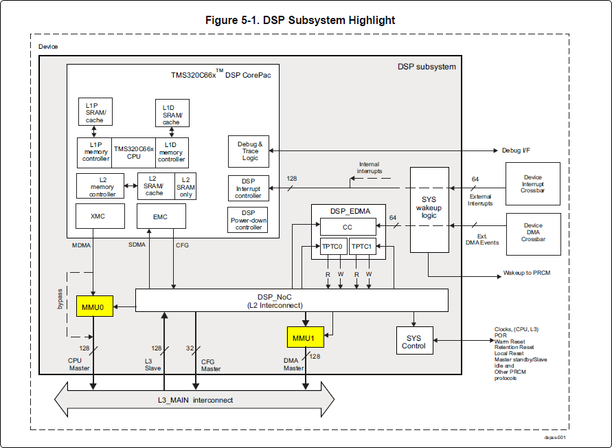
DSP Physical Addresses
The physical location where the DSP code/data will actually reside is defined by the CMA carveout. To change this location, you must change the definition of the carveout. The DSP carveouts are defined in the Linux dts file. For example for the AM57xx EVM:
dsp1_cma_pool: dsp1_cma@99000000 {
compatible = "shared-dma-pool";
reg = <0x0 0x99000000 0x0 0x4000000>;
reusable;
status = "okay";
};
dsp2_cma_pool: dsp2_cma@9f000000 {
compatible = "shared-dma-pool";
reg = <0x0 0x9f000000 0x0 0x800000>;
reusable;
status = "okay";
};
};
You are able to change both the size and location. Be careful not to overlap any other carveouts!
Note
The two location entries for a given DSP must be identical!
Additionally, when you change the carveout location, there is a corresponding change that must be made to the resource table. For starters, if you’re making a memory change you will need a custom resource table. The resource table is a large structure that is the “bridge” between physical memory and virtual memory. This structure is utilized for configuring the MMUs that sit in front of the DSP subsystem. There is detailed information available in the article IPC Resource customTable.
Once you’ve created your custom resource table, you must update the address of PHYS_MEM_IPC_VRING to be the same base address as your corresponding CMA.
#if defined (VAYU_DSP_1)
#define PHYS_MEM_IPC_VRING 0x99000000
#elif defined (VAYU_DSP_2)
#define PHYS_MEM_IPC_VRING 0x9F000000
#endif
Note
The PHYS_MEM_IPC_VRING definition from the resource table must match the address of the associated CMA carveout!
DSP Virtual Addresses
These addresses are the ones seen by the DSP subsystem, i.e. these will be the addresses in your linker command files, etc.
You must ensure that the sizes of your sections are consistent with the corresponding definitions in the resource table. You should create your own resource table in order to modify the memory map. This is describe in the wiki page IPC Resource customTable. You can look at an existing resource table inside IPC:
ipc/packages/ti/ipc/remoteproc/rsc_table_vayu_dsp.h
{
TYPE_CARVEOUT,
DSP_MEM_TEXT, 0,
DSP_MEM_TEXT_SIZE, 0, 0, "DSP_MEM_TEXT",
},
{
TYPE_CARVEOUT,
DSP_MEM_DATA, 0,
DSP_MEM_DATA_SIZE, 0, 0, "DSP_MEM_DATA",
},
{
TYPE_CARVEOUT,
DSP_MEM_HEAP, 0,
DSP_MEM_HEAP_SIZE, 0, 0, "DSP_MEM_HEAP",
},
{
TYPE_CARVEOUT,
DSP_MEM_IPC_DATA, 0,
DSP_MEM_IPC_DATA_SIZE, 0, 0, "DSP_MEM_IPC_DATA",
},
{
TYPE_TRACE, TRACEBUFADDR, 0x8000, 0, "trace:dsp",
},
{
TYPE_DEVMEM,
DSP_MEM_IPC_VRING, PHYS_MEM_IPC_VRING,
DSP_MEM_IPC_VRING_SIZE, 0, 0, "DSP_MEM_IPC_VRING",
},
Let’s have a look at some of these to understand them better. For example:
{
TYPE_CARVEOUT,
DSP_MEM_TEXT, 0,
DSP_MEM_TEXT_SIZE, 0, 0, "DSP_MEM_TEXT",
},
Key points to note are:
- The “TYPE_CARVEOUT” indicates that the physical memory backing this entry will come from the associated CMA pool.
- DSP_MEM_TEXT is a #define earlier in the code providing the address for the code section. It is 0x95000000 by default. This must correspond to a section from your DSP linker command file, i.e. EXT_CODE (or whatever name you choose to give it) must be linked to the same address.
- DSP_MEM_TEXT_SIZE is the size of the MMU pagetable entry being created (1MB in this particular instance). The actual amount of linked code in the corresponding section of your executable must be less than or equal to this size.
Let’s take another:
{
TYPE_TRACE, TRACEBUFADDR, 0x8000, 0, "trace:dsp",
},
Key points are:
- The “TYPE_TRACE” indicates this is for trace info.
- The TRACEBUFADDR is defined earlier in the file as &ti_trace_SysMin_Module_State_0_outbuf__A. That corresponds to the symbol used in TI-RTOS for the trace buffer.
- The “0x8000” is the size of the MMU mapping. The corresponding size in the cfg file should be the same (or less). It looks like this: SysMin.bufSize = 0x8000;
Finally, let’s look at a TYPE_DEVMEM example:
{
TYPE_DEVMEM,
DSP_PERIPHERAL_L4CFG, L4_PERIPHERAL_L4CFG,
SZ_16M, 0, 0, "DSP_PERIPHERAL_L4CFG",
},
Key points:
- The “TYPE_DEVMEM” indicates that we are making an MMU mapping, but this does not come from the CMA pool. This is intended for mapping peripherals, etc. that already exist in the device memory map.
- DSP_PERIPHERAL_L4CFG (0x4A000000) is the virtual address while L4_PERIPHERAL_L4CFG (0x4A000000) is the physical address. This is an identity mapping, meaning that peripherals can be referenced by the DSP using their physical address.
DSP Access to Peripherals
The default resource table creates the following mappings:
| Virtual Address | Physical Address | Size | Comment |
|---|---|---|---|
| 0x4A000000 | 0x4A000000 | 16 MB | L4CFG + L4WKUP |
| 0x48000000 | 0x48000000 | 2 MB | L4PER1 |
| 0x48400000 | 0x48400000 | 4 MB | L4PER2 |
| 0x48800000 | 0x48800000 | 8 MB | L4PER3 |
| 0x54000000 | 0x54000000 | 16 MB | L3_INSTR + CT_TBR |
| 0x4E000000 | 0x4E000000 | 1 MB | DMM config |
In other words, the peripherals can be accessed at their physical addresses since we use an identity mapping.
Inspecting the DSP IOMMU Page Tables at Run-Time
You can dump the DSP IOMMU page tables with the following commands:
| DSP | MMU | Command |
|---|---|---|
| DSP1 | MMU0 | cat /sys/kernel/debug/omap_iommu/40d01000.mmu/pagetable |
| DSP1 | MMU1 | cat /sys/kernel/debug/omap_iommu/40d02000.mmu/pagetable |
| DSP2 | MMU0 | cat /sys/kernel/debug/omap_iommu/41501000.mmu/pagetable |
| DSP2 | MMU1 | cat /sys/kernel/debug/omap_iommu/41502000.mmu/pagetable |
In general, MMU0 and MMU1 are being programmed identically so you really only need to take a look at one or the other to understand the mapping for a given DSP.
For example:
root@am57xx-evm:~# cat /sys/kernel/debug/omap_iommu/40d01000.mmu/pagetable
L: da: pte:
--------------------------
1: 0x48000000 0x48000002
1: 0x48100000 0x48100002
1: 0x48400000 0x48400002
1: 0x48500000 0x48500002
1: 0x48600000 0x48600002
1: 0x48700000 0x48700002
1: 0x48800000 0x48800002
1: 0x48900000 0x48900002
1: 0x48a00000 0x48a00002
1: 0x48b00000 0x48b00002
1: 0x48c00000 0x48c00002
1: 0x48d00000 0x48d00002
1: 0x48e00000 0x48e00002
1: 0x48f00000 0x48f00002
1: 0x4a000000 0x4a040002
1: 0x4a100000 0x4a040002
1: 0x4a200000 0x4a040002
1: 0x4a300000 0x4a040002
1: 0x4a400000 0x4a040002
1: 0x4a500000 0x4a040002
1: 0x4a600000 0x4a040002
1: 0x4a700000 0x4a040002
1: 0x4a800000 0x4a040002
1: 0x4a900000 0x4a040002
1: 0x4aa00000 0x4a040002
1: 0x4ab00000 0x4a040002
1: 0x4ac00000 0x4a040002
1: 0x4ad00000 0x4a040002
1: 0x4ae00000 0x4a040002
1: 0x4af00000 0x4a040002
The first column tells us whether the mapping is a Level 1 or Level 2 descriptor. All the lines above are a first level descriptor, so we look at the associated format from the TRM:
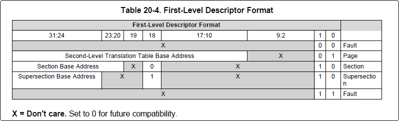
The “da” (“device address”) column reflects the virtual address. It is derived from the index into the table, i.e. there does not exist a “da” register or field in the page table. Each MB of the address space maps to an entry in the table. The “da” column is displayed to make it easy to find the virtual address of interest.
The “pte” (“page table entry”) column can be decoded according to Table 20-4 shown above. For example:
1: 0x4a000000 0x4a040002
The 0x4a040002 shows us that it is a Supersection with base address 0x4A000000. This gives us a 16 MB memory page. Note the repeated entries afterward. That’s a requirement of the MMU. Here’s an excerpt from the TRM:
Note
Supersection descriptors must be repeated 16 times, because each descriptor in the first level translation table describes 1 MiB of memory. If an access points to a descriptor that is not initialized, the MMU will behave in an unpredictable way.
Changing Cortex M4 IPU Memory Map
In order to fully understand the memory mapping of the Cortex M4 IPU Subsystems, it’s helpful to recognize that there are two distinct/independent levels of memory translation. Here’s a snippet from the TRM to illustrate:
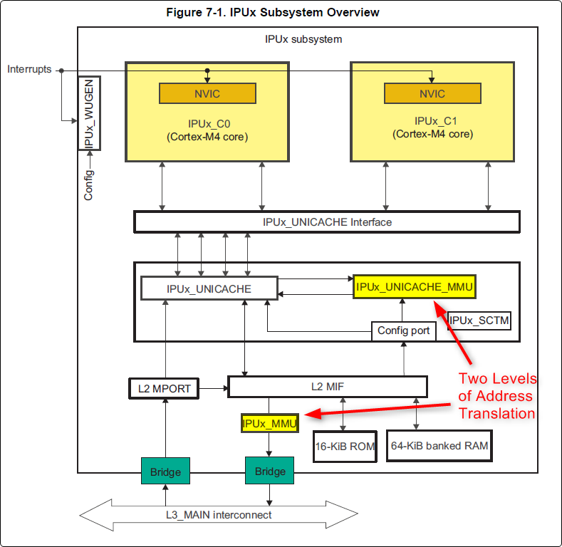
Cortex M4 IPU Physical Addresses
The physical location where the M4 code/data will actually reside is defined by the CMA carveout. To change this location, you must change the definition of the carveout. The M4 carveouts are defined in the Linux dts file. For example for the AM57xx EVM:
ipu2_cma_pool: ipu2_cma@95800000 {
compatible = "shared-dma-pool";
reg = <0x0 95800000 0x0 0x3800000>;
reusable;
status = "okay";
};
ipu1_cma_pool: ipu1_cma@9d000000 {
compatible = "shared-dma-pool";
reg = <0x0 9d000000 0x0 0x2000000>;
reusable;
status = "okay";
};
};
Note
The two location entries for a given carveout must be identical!
Once you’ve created your custom resource table, you must update the address of PHYS_MEM_IPC_VRING to be the same base address as your corresponding CMA.
#if defined(VAYU_IPU_1)
#define PHYS_MEM_IPC_VRING 0x9D000000
#elif defined (VAYU_IPU_2)
#define PHYS_MEM_IPC_VRING 0x95800000
#endif
Note
The PHYS_MEM_IPC_VRING definition from the resource table must match the address of the associated CMA carveout!
Cortex M4 IPU Virtual Addresses
Unicache MMU
The Unicache MMU sits closest to the Cortex M4. It provides the first level of address translation. The Unicache MMU is actually “self programmed” by the Cortex M4. The Unicache MMU is also referred to as the Attribute MMU (AMMU). There are a fixed number of small, medium and large pages. Here’s a snippet showing some of the key mappings:
ipc_3_43_02_04/examples/DRA7XX_linux_elf/ex02_messageq/ipu1/IpuAmmu.cfg
/*********************** Large Pages *************************/
/* Instruction Code: Large page (512M); cacheable */
/* config large page[0] to map 512MB VA 0x0 to L3 0x0 */
AMMU.largePages[0].pageEnabled = AMMU.Enable_YES;
AMMU.largePages[0].logicalAddress = 0x0;
AMMU.largePages[0].translationEnabled = AMMU.Enable_NO;
AMMU.largePages[0].size = AMMU.Large_512M;
AMMU.largePages[0].L1_cacheable = AMMU.CachePolicy_CACHEABLE;
AMMU.largePages[0].L1_posted = AMMU.PostedPolicy_POSTED;
/* Peripheral regions: Large Page (512M); non-cacheable */
/* config large page[1] to map 512MB VA 0x60000000 to L3 0x60000000 */
AMMU.largePages[1].pageEnabled = AMMU.Enable_YES;
AMMU.largePages[1].logicalAddress = 0x60000000;
AMMU.largePages[1].translationEnabled = AMMU.Enable_NO;
AMMU.largePages[1].size = AMMU.Large_512M;
AMMU.largePages[1].L1_cacheable = AMMU.CachePolicy_NON_CACHEABLE;
AMMU.largePages[1].L1_posted = AMMU.PostedPolicy_POSTED;
/* Private, Shared and IPC Data regions: Large page (512M); cacheable */
/* config large page[2] to map 512MB VA 0x80000000 to L3 0x80000000 */
AMMU.largePages[2].pageEnabled = AMMU.Enable_YES;
AMMU.largePages[2].logicalAddress = 0x80000000;
AMMU.largePages[2].translationEnabled = AMMU.Enable_NO;
AMMU.largePages[2].size = AMMU.Large_512M;
AMMU.largePages[2].L1_cacheable = AMMU.CachePolicy_CACHEABLE;
AMMU.largePages[2].L1_posted = AMMU.PostedPolicy_POSTED;
| Page | Cortex M4 Address | Intermediate Address | Size | Comment |
|---|---|---|---|---|
| Large Page 0 | 0x00000000-0x1fffffff | 0x00000000-0x1fffffff | 512 MB | Code |
| Large Page 1 | 0x60000000-0x7fffffff | 0x60000000-0x7fffffff | 512 MB | Peripherals |
| Large Page 2 | 0x80000000-0x9fffffff | 0x80000000-0x9fffffff | 512 MB | Data |
These 3 pages are “identity” mappings, performing a passthrough of requests to the associated address ranges. These intermediate addresses get mapped to their physical addresses in the next level of translation (IOMMU).
The AMMU ranges for code and data need to be identity mappings because otherwise the remoteproc loader wouldn’t be able to match up the sections from the ELF file with the associated IOMMU mapping. These mappings should suffice for any application, i.e. no need to adjust these. The more likely area for modification is the resource table in the next section. The AMMU mappings are needed mainly to understand the full picture with respect to the Cortex M4 memory map.
IOMMU
The IOMMU sits closest to the L3 interconnect. It takes the intermediate address output from the AMMU and translates it to the physical address used by the L3 interconnect. The IOMMU is programmed by the ARM based on the associated resource table. If you’re planning any memory changes then you’ll want to make a custom resource table as described in the wiki page IPC Resource customTable.
The default resource table (which can be adapted to make a custom table) can be found at this location:
ipc/packages/ti/ipc/remoteproc/rsc_table_vayu_ipu.h
#define IPU_MEM_TEXT 0x0
#define IPU_MEM_DATA 0x80000000
#define IPU_MEM_IOBUFS 0x90000000
#define IPU_MEM_IPC_DATA 0x9F000000
#define IPU_MEM_IPC_VRING 0x60000000
#define IPU_MEM_RPMSG_VRING0 0x60000000
#define IPU_MEM_RPMSG_VRING1 0x60004000
#define IPU_MEM_VRING_BUFS0 0x60040000
#define IPU_MEM_VRING_BUFS1 0x60080000
#define IPU_MEM_IPC_VRING_SIZE SZ_1M
#define IPU_MEM_IPC_DATA_SIZE SZ_1M
#if defined(VAYU_IPU_1)
#define IPU_MEM_TEXT_SIZE (SZ_1M)
#elif defined(VAYU_IPU_2)
#define IPU_MEM_TEXT_SIZE (SZ_1M * 6)
#endif
#if defined(VAYU_IPU_1)
#define IPU_MEM_DATA_SIZE (SZ_1M * 5)
#elif defined(VAYU_IPU_2)
#define IPU_MEM_DATA_SIZE (SZ_1M * 48)
#endif
<snip...>
{
TYPE_CARVEOUT,
IPU_MEM_TEXT, 0,
IPU_MEM_TEXT_SIZE, 0, 0, "IPU_MEM_TEXT",
},
{
TYPE_CARVEOUT,
IPU_MEM_DATA, 0,
IPU_MEM_DATA_SIZE, 0, 0, "IPU_MEM_DATA",
},
{
TYPE_CARVEOUT,
IPU_MEM_IPC_DATA, 0,
IPU_MEM_IPC_DATA_SIZE, 0, 0, "IPU_MEM_IPC_DATA",
},
The 3 entries above from the resource table all come from the associated IPU CMA pool (i.e. as dictated by the TYPE_CARVEOUT). The second parameter represents the virtual address (i.e. input address to the IOMMU). These addresses must be consistent with both the AMMU mapping as well as the linker command file. The ex02_messageq example from ipc defines these memory sections in the file examples/DRA7XX_linux_elf/ex02_messageq/shared/config.bld.
You can dump the IPU IOMMU page tables with the following commands:
| IPU | Command |
|---|---|
| IPU1 | cat /sys/kernel/debug/omap_iommu/58882000.mmu/pagetable |
| IPU2 | cat /sys/kernel/debug/omap_iommu/55082000.mmu/pagetable |
Please see the corresponding DSP documentation for more details on interpreting the output.
Cortex M4 IPU Access to Peripherals
The default resource table creates the following mappings:
| Virtual Address used by Cortex M4 | Address at output of Unicache MMU | Address at output of IOMMU | Size | Comment |
|---|---|---|---|---|
| 0x6A000000 | 0x6A000000 | 0x4A000000 | 16 MB | L4CFG + L4WKUP |
| 0x68000000 | 0x68000000 | 0x48000000 | 2 MB | L4PER1 |
| 0x68400000 | 0x68400000 | 0x48400000 | 4 MB | L4PER2 |
| 0x68800000 | 0x68800000 | 0x48800000 | 8 MB | L4PER3 |
| 0x74000000 | 0x74000000 | 0x54000000 | 16 MB | L3_INSTR + CT_TBR |
Example: Accessing UART5 from IPU
- For this example, it’s assumed the pin-muxing was already setup in the bootloader. If that’s not the case, you would need to do that here.
- The UART5 module needs to be enabled via the CM_L4PER_UART5_CLKCTRL register. This is located at physical address 0x4A009870. So from the M4 we would program this register at virtual address 0x6A009870. Writing a value of 2 to this register will enable the peripheral.
- After completing the previous step, the UART5 registers will become accessible. Normally UART5 is accessible at physical base address 0x48066000. This would correspondingly be accessed from the IPU at 0x68066000.
Power Management
The IPUs and DSPs auto-idle by default. This can prevent you from being able to connect to the device using JTAG or from accessing local memory via devmem2. There are some options sprinkled throughout sysfs that are needed in order to force these subsystems on, as is sometimes needed for development and debug purposes.
There are some hard-coded device names that originate in the device tree (dra7.dtsi) that are needed for these operations:
| Remote Core | Definition in dra7.dtsi | System FS Name |
|---|---|---|
| IPU1 | ipu@58820000 | 58820000.ipu |
| IPU2 | ipu@55020000 | 55020000.ipu |
| DSP1 | dsp@40800000 | 40800000.dsp |
| DSP2 | dsp@41000000 | 41000000.dsp |
| ICSS1-PRU0 | pru@4b234000 | 4b234000.pru0 |
| ICSS1-PRU1 | pru@4b238000 | 4b238000.pru1 |
| ICSS2-PRU0 | pru@4b2b4000 | 4b2b4000.pru0 |
| ICSS2-PRU1 | pru@4b2b8000 | 4b2b8000.pru1 |
To map these System FS names to the associated remoteproc entry, you can run the following commands:
root@am57xx-evm:~# ls -l /sys/kernel/debug/remoteproc/
root@am57xx-evm:~# cat /sys/kernel/debug/remoteproc/remoteproc*/name
The results of the commands will be a one-to-one mapping. For example, 58820000.ipu corresponds with remoteproc0.
Similarly, to see the power state of each of the cores:
root@am57xx-evm:~# cat /sys/class/remoteproc/remoteproc*/state
The state can be suspended, running, offline, etc. You can only attach JTAG if the state is “running”. If it shows as “suspended” then you must force it to run. For example, let’s say DSP0 is “suspended”. You can run the following command to force it on:
root@am57xx-evm:~# echo on > /sys/bus/platform/devices/40800000.dsp/power/control
The same is true for any of the cores, but replace 40800000.dsp with the associated System FS name from the chart above.
Adding IPC to an Existing TI-RTOS Application on slave cores
Adding IPC to an existing TI RTOS application on the DSP
A common thing people want to do is take an existing DSP application and add IPC to it. This is common when migrating from a DSP only solution to a heterogeneous SoC with an Arm plus a DSP. This is the focus of this section.
In order to describe this process, we need an example test case to work with. For this purpose, we’ll be using the GPIO_LedBlink_evmAM572x_c66xExampleProject example that’s part of the PDK (installed as part of the Processor SDK RTOS). You can find it at c:\ti\pdk_am57xx_1_0_4\packages\MyExampleProjects\GPIO_LedBlink_evmAM572x_c66xExampleProject. This example uses SYS/BIOS and blinks the USER0 LED on the AM572x GP EVM, it’s labeled D4 on the EVM silkscreen just to the right of the blue reset button.
There were several steps taken to make this whole process work, each of which will be described in following sections
- Build and run the out-of-box LED blink example on the EVM using Code Composer Studio (CCS)
- Take the ex02_message example from the IPC software bundle and turn it into a CCS project. Build it and modify the Linux startup code to use this new image. This is just a sanity check step to make sure we can build the IPC examples in CCS and have them run at boot up on the EVM.
- In CCS, make a clone of the out-of-box LED example and rename it to denote it’s the IPC version of the example. Then using the ex02_messageq example as a reference, add in the IPC pieces to the LED example. Build from CCS then add it to the Linux firmware folder.
Running LED Blink PDK Example from CCS
TODO - Fill this section in with instructions on how to run the LED blink example using JTAG and CCS after the board has booted Linux.
Note
Some edits were made to the LED blink example to allow it to run in a Linux environment, specifically, removed the GPIO interrupts and then added a Clock object to call the LED GPIO toggle function on a periodic bases.
Make CCS project out of ex02_messageq IPC example
TODO - fill this section in with instructions on how to make a CCS project out of the IPC example source files.
Add IPC to the LED Blink Example
The first step is to clone our out-of-box LED blink CCS project and rename it to denote it’s using IPC. The easiest way to do this is using CCS. Here are the steps...
- In the Edit perspective, go into your Project Explorer window and right click on your GPIO_LedBlink_evmAM572x+c66xExampleProject project and select copy from the pop-up menu. Maske sure the project is not is a closed state.
- Rick click in and empty area of the project explorer window and select past.
- A dialog box pops up, modify the name to denote it’s using IPC. A good name is GPIO_LedBlink_evmAM572x+c66xExampleProjec_with_ipc.
This is the project we’ll be working with from here on. The next thing we want to do is select the proper RTSC platform and other components. To do this, follow these steps.
- Right click on the GPIO_LedBlink_evmAM572x+c66xExampleProjec_with_ipc project and select Properties
- In the left hand pane, click on CCS General.
- On the right hand side, click on the RTSC tab
- For XDCtools version: select 3.32.0.06_core
- In the list of Products and Repositories, check the following...
- IPC 3.43.2.04
- SYS/BIOS 6.45.1.29
- am57xx PDK 1.0.4
- For Target, select ti.targets.elf.C66
- For Platform, select ti.platforms.evmDRA7XX
- Once the platform is selected, edit its name buy hand and append :dsp1 to the end. After this it should be ti.platforms.evmDRA7XX:dsp1
- Go ahead and leave the Build-profile set to debug.
- Hit the OK button.
Now we want to copy configuration and source files from the ex02_messageq IPC example into our project. The IPC example is located at C:\ti\ipc_3_43_02_04\examples\DRA7XX_linux_elf\ex02_messageq. To copy files into your CCS project, you can simply select the files you want in Windows explorer then drag and drop them into your project in CCS.
Copy these files into your CCS project...
- C:\ti\ipc_3_43_02_04\examples\DRA7XX_linux_elf\ex02_messageq\shared\AppCommon.h
- C:\ti\ipc_3_43_02_04\examples\DRA7XX_linux_elf\ex02_messageq\shared\config.bld
- C:\ti\ipc_3_43_02_04\examples\DRA7XX_linux_elf\ex02_messageq\shared\ipc.cfg.xs
Now copy these files into your CCS project...
- C:\ti\ipc_3_43_02_04\examples\DRA7XX_linux_elf\ex02_messageq\dsp1\Dsp1.cfg
- C:\ti\ipc_3_43_02_04\examples\DRA7XX_linux_elf\ex02_messageq\dsp1\MainDsp1.c
- C:\ti\ipc_3_43_02_04\examples\DRA7XX_linux_elf\ex02_messageq\dsp1\Server.c
- C:\ti\ipc_3_43_02_04\examples\DRA7XX_linux_elf\ex02_messageq\dsp1\Server.h
Note
When you copy Dsp1.cfg into your CCS project, it should show up greyed out. This is because the LED blink example already has a cfg file (gpio_test_evmAM572x.cfg). The Dsp1.cfg will be used for copying and pasting. When it’s all done, you can delete it from your project.
Finally, you will likely want to use a custom resource table so copy these files into your CCS project...
- C:\ti\ipc_3_43_02_04\packages\ti\ipc\remoteproc\rsc_table_vayu_dsp.h
- C:\ti\ipc_3_43_02_04\packages\ti\ipc\remoteproc\rsc_types.h
The rsc_table_vayu_dsp.h file defines an initialized structure so let’s make a .c source file.
- In your CCS project, rename rsc_table_vayu_dsp.h to rsc_table_vayu_dsp.c
Now we want to merge the IPC example configuration file with the LED blink example configuration file. Follow these steps...
- Open up Dsp1.cfg using a text editor (don’t open it using the GUI). Right click on it and select Open With -> XDCscript Editor
- We want to copy the entire contents into the clipboard. Select all and copy.
- Now just like above, open the gpio_test_evmAM572x.cfg config file in the text editor. Go to the very bottom and paste in the contents from the Dsp1.cfg file. Basically we’ve appended the contents of Dsp1.cfg into gpio_test_evmAM572x.cfg.
We’ve now added in all the necessary configuration and source files into our project. Don’t expect it to build at this point, we have to make edits first. These edits are listed below.
NOTE, you can download the full CCS project with source files to use as a reference.
See link towards the end of this section.
- Edit gpio_test_evmAM572x.cfg
Add the following to the beginning of your configuration file
var Program = xdc.useModule('xdc.cfg.Program');
Comment out the Memory sections configuration as shown below
/* ================ Memory sections configuration ================ */
//Program.sectMap[".text"] = "EXT_RAM";
//Program.sectMap[".const"] = "EXT_RAM";
//Program.sectMap[".plt"] = "EXT_RAM";
/* Program.sectMap["BOARD_IO_DELAY_DATA"] = "OCMC_RAM1"; */
/* Program.sectMap["BOARD_IO_DELAY_CODE"] = "OCMC_RAM1"; */
Since we are no longer using a shared folder, make the following change
//var ipc_cfg = xdc.loadCapsule("../shared/ipc.cfg.xs");
var ipc_cfg = xdc.loadCapsule("../ipc.cfg.xs");
Comment out the following. We’ll be calling this function directly from main.
//BIOS.addUserStartupFunction('&IpcMgr_ipcStartup');
Increase the system stack size
//Program.stack = 0x1000;
Program.stack = 0x8000;
Comment out the entire TICK section
/* --------------------------- TICK --------------------------------------*/
// var Clock = xdc.useModule('ti.sysbios.knl.Clock');
// Clock.tickSource = Clock.TickSource_NULL;
// //Clock.tickSource = Clock.TickSource_USER;
// /* Configure BIOS clock source as GPTimer5 */
// //Clock.timerId = 0;
//
// var Timer = xdc.useModule('ti.sysbios.timers.dmtimer.Timer');
//
// /* Skip the Timer frequency verification check. Need to remove this later */
// Timer.checkFrequency = false;
//
// /* Match this to the SYS_CLK frequency sourcing the dmTimers.
// * Not needed once the SYS/BIOS family settings is updated. */
// Timer.intFreq.hi = 0;
// Timer.intFreq.lo = 19200000;
//
// //var timerParams = new Timer.Params();
// //timerParams.period = Clock.tickPeriod;
// //timerParams.periodType = Timer.PeriodType_MICROSECS;
// /* Switch off Software Reset to make the below settings effective */
// //timerParams.tiocpCfg.softreset = 0x0;
// /* Smart-idle wake-up-capable mode */
// //timerParams.tiocpCfg.idlemode = 0x3;
// /* Wake-up generation for Overflow */
// //timerParams.twer.ovf_wup_ena = 0x1;
// //Timer.create(Clock.timerId, Clock.doTick, timerParams);
//
// var Idle = xdc.useModule('ti.sysbios.knl.Idle');
// var Deh = xdc.useModule('ti.deh.Deh');
//
// /* Must be placed before pwr mgmt */
// Idle.addFunc('&ti_deh_Deh_idleBegin');
Make configuration change to use custom resource table. Add to the end of the file.
/* Override the default resource table with my own */
var Resource = xdc.useModule('ti.ipc.remoteproc.Resource');
Resource.customTable = true;
- Edit main_led_blink.c
Add the following external declarations
extern Int ipc_main();
extern Void IpcMgr_ipcStartup(Void);
In main(), add a call to ipc_main() and IpcMgr_ipcStartup() just before BIOS_start()
ipc_main();
if (callIpcStartup) {
IpcMgr_ipcStartup();
}
/* Start BIOS */
BIOS_start();
return (0);
Comment out the line that calls Board_init(boardCfg). This call is in the original example because it assumes TI-RTOS is running on the Arm but in our case here, we are running Linux and this call is destructive so we comment it out.
#if defined(EVM_K2E) || defined(EVM_C6678)
boardCfg = BOARD_INIT_MODULE_CLOCK |
BOARD_INIT_UART_STDIO;
#else
boardCfg = BOARD_INIT_PINMUX_CONFIG |
BOARD_INIT_MODULE_CLOCK |
BOARD_INIT_UART_STDIO;
#endif
//Board_init(boardCfg);
- Edit MainDsp1.c
The app now has it’s own main(), so rename this one and get rid of args
//Int main(Int argc, Char* argv[])
Int ipc_main()
{
No longer using args so comment these lines
//taskParams.arg0 = (UArg)argc;
//taskParams.arg1 = (UArg)argv;
BIOS_start() is done in the app main() so comment it out here
/* start scheduler, this never returns */
//BIOS_start();
Comment this out
//Log_print0(Diags_EXIT, "<-- main:");
- Edit rsc_table_vayu_dsp.c
Set this #define before it’s used to select PHYS_MEM_IPC_VRING value
#define VAYU_DSP_1
Add this extern declaration prior to the symbol being used
extern char ti_trace_SysMin_Module_State_0_outbuf__A;
- Edit Server.c
No longer have shared folder so change include path
/* local header files */
//#include "../shared/AppCommon.h"
#include "../AppCommon.h"
Download the Full CCS Project
GPIO_LedBlink_evmAM572x_c66xExampleProject_with_ipc.zip
Adding IPC to an existing TI RTOS application on the IPU
A common thing people want to do is take an existing IPU application that may be controlling serial or control interfaces and add IPC to it so that the firmware can be loaded from the ARM. This is common when migrating from a IPU only solution to a heterogeneous SoC with an MPUSS (ARM) and IPUSS. This is the focus of this section.
In order to describe this process, we need an example TI RTOS test case to work with. For this purpose, we’ll be using the UART_BasicExample_evmAM572x_m4ExampleProject example that’s part of the PDK (installed as part of the Processor SDK RTOS). This example uses TI RTOS and does serial IO using UART3 port on the AM572x GP EVM, it’s labeled Serial Debug on the EVM silkscreen.
There were several steps taken to make this whole process work, each of which will be described in following sections
- Build and run the out-of-box UART M4 example on the EVM using Code Composer Studio (CCS)
- Build and run the ex02_messageQ example from the IPC software bundle and turn it into a CCS project. Build it and modify the Linux startup code to use this new image. This is just a sanity check step to make sure we can build the IPC examples in CCS and have them run at boot up on the EVM.
- In CCS, make a clone of the out-of-box UART M4 example and rename it to denote it’s the IPC version of the example. Then using the ex02_messageq example as a reference, add in the IPC pieces to the UART example code. Build from CCS then add it to the Linux firmware folder.
Running UART Read/Write PDK Example from CCS
Developers are required to run pdkProjectCreate script to generate this example as described in the Processor SDK RTOS wiki article.
For the UART M4 example run the script with the following arguments:
pdkProjectCreate.bat AM572x evmAM572x little uart m4
After you run the script, you can find the UART M4 example project at <SDK_INSTALL_PATH>\pdk_am57xx_1_0_4\packages\MyExampleProjects\UART_BasicExample_evmAM572x_m4ExampleProject.
Import the project in CCS and build the example. You can now connect to the EVM using an emulator and CCS using the instructions provided here: https://processors.wiki.ti.com/index.php/AM572x_GP_EVM_Hardware_Setup
Connect to the ARM core and make sure GEL runs multicore initialization and brings the IPUSS out of reset. Connect to IPU2 core0 and load and run the M4 UART example. When you run the code you should see the following log on the serial IO console:
uart driver and utils example test cases :
Enter 16 characters or press Esc
1234567890123456 <- user input
Data received is
1234567890123456 <- loopback from user input
uart driver and utils example test cases :
Enter 16 characters or press Esc
Build and Run ex02_messageq IPC example
Follow instructions described in Article Run IPC Linux Examples
Update Linux Kernel device tree to remove UART that will be controlled by M4
Linux kernel enables all SOC HW modules which are required for its configuration. Appropriate drivers configure required clocks and initialize HW registers. For all unused IPs clocks are not configured.
The uart3 node is disabled in kernel using device tree. Also this restricts kernel to put those IPs to sleep mode.
&uart3 {
status = "disabled";
ti,no-idle;
};
Add IPC to the UART Example
The first step is to clone our out-of-box UART example CCS project and rename it to denote it’s using IPC. The easiest way to do this is using CCS. Here are the steps...
- In the Edit perspective, go into your Project Explorer window and right click on your UART_BasicExample_evmAM572x_m4ExampleProject project and select copy from the pop-up menu. Maske sure the project is not is a closed state.
- Rick click in and empty area of the project explorer window and select past.
- A dialog box pops up, modify the name to denote it’s using IPC. A good name is UART_BasicExample_evmAM572x_m4ExampleProject_with_ipc.
This is the project we’ll be working with from here on. The next thing we want to do is select the proper RTSC platform and other components. To do this, follow these steps.
- Right click on the UART_BasicExample_evmAM572x_m4ExampleProject_with_ipc project and select Properties
- In the left hand pane, click on CCS General.
- On the right hand side, click on the RTSC tab
- For XDCtools version: select 3.xx.x.xx_core
- In the list of Products and Repositories, check the following...
- IPC 3.xx.x.xx
- SYS/BIOS 6.4x.x.xx
- am57xx PDK x.x.x
- For Target, select ti.targets.arm.elf.M4
- For Platform, select ti.platforms.evmDRA7XX
- Once the platform is selected, edit its name buy hand and append :ipu2 to the end. After this it should be ti.platforms.evmDRA7XX:ipu2
- Go ahead and leave the Build-profile set to debug.
- Hit the OK button.
Now we want to copy configuration and source files from the ex02_messageq IPC example into our project. The IPC example is located at C:\ti\ipc_3_xx_xx_xx\examples\DRA7XX_linux_elf\ex02_messageq. To copy files into your CCS project, you can simply select the files you want in Windows explorer then drag and drop them into your project in CCS.
Copy these files into your CCS project...
- C:\ti\ipc_3_xx_xx_xx\examples\DRA7XX_linux_elf\ex02_messageq\shared\AppCommon.h
- C:\ti\ipc_3_xx_xx_xx\examples\DRA7XX_linux_elf\ex02_messageq\shared\config.bld
- C:\ti\ipc_3_xx_xx_xx\examples\DRA7XX_linux_elf\ex02_messageq\shared\ipc.cfg.xs
Now copy these files into your CCS project...
- C:\ti\ipc_3_xx_xx_xx\examples\DRA7XX_linux_elf\ex02_messageq\ipu2\Ipu2.cfg
- C:\ti\ipc_3_xx_xx_xx\examples\DRA7XX_linux_elf\ex02_messageq\ipu2\MainIpu2.c
- C:\ti\ipc_3_xx_xx_xx\examples\DRA7XX_linux_elf\ex02_messageq\ipu2\Server.c
- C:\ti\ipc_3_xx_xx_xx\examples\DRA7XX_linux_elf\ex02_messageq\ipu2\Server.h
Note
When you copy Ipu2.cfg into your CCS project, it should show up greyed out. If not, right click and exclude it from build. This is because the UART example already has a cfg file (uart_m4_evmAM572x.cfg). The Ipu2.cfg will be used for copying and pasting. When it’s all done, you can delete it from your project.
Finally, you will likely want to use a custom resource table so copy these files into your CCS project...
- C:\ti\ipc_3_xx_xx_xx\packages\ti\ipc\remoteproc\rsc_table_vayu_ipu.h
- C:\ti\ipc_3_xx_xx_xx\packages\ti\ipc\remoteproc\rsc_types.h
The rsc_table_vayu_dsp.h file defines an initialized structure so let’s make a .c source file.
- In your CCS project, rename rsc_table_vayu_ipu.h to rsc_table_vayu_ipu.c
Now we want to merge the IPC example configuration file with the LED blink example configuration file. Follow these steps...
- Open up Ipu2.cfg using a text editor (don’t open it using the GUI). Right click on it and select Open With -> XDCscript Editor
- We want to copy the entire contents into the clipboard. Select all and copy.
- Now just like above, open the uart_m4_evmAM572x.cfg config file in the text editor. Go to the very bottom and paste in the contents from the Ipu2.cfg file. Basically we’ve appended the contents of Ipu2.cfg into uart_m4_evmAM572x.cfg.
We’ve now added in all the necessary configuration and source files into our project. Don’t expect it to build at this point, we have to make edits first. These edits are listed below.
NOTE, you can download the full CCS project with source files to use as a reference.
See link towards the end of this section.
- Edit uart_m4_evmAM572x.cfg
Add the following to the beginning(at the top) of your configuration file
var Program = xdc.useModule('xdc.cfg.Program');
Since we are no longer using a shared folder, make the following change
//var ipc_cfg = xdc.loadCapsule("../shared/ipc.cfg.xs");
var ipc_cfg = xdc.loadCapsule("../ipc.cfg.xs");
Comment out the following. We’ll be calling this function directly from main.
//BIOS.addUserStartupFunction('&IpcMgr_ipcStartup');
Increase the system stack size
//Program.stack = 0x1000;
Program.stack = 0x8000;
Comment out the entire TICK section
/* --------------------------- TICK --------------------------------------*/
// var Clock = xdc.useModule('ti.sysbios.knl.Clock');
// Clock.tickSource = Clock.TickSource_NULL;
// //Clock.tickSource = Clock.TickSource_USER;
// /* Configure BIOS clock source as GPTimer5 */
// //Clock.timerId = 0;
//
// var Timer = xdc.useModule('ti.sysbios.timers.dmtimer.Timer');
//
// /* Skip the Timer frequency verification check. Need to remove this later */
// Timer.checkFrequency = false;
//
// /* Match this to the SYS_CLK frequency sourcing the dmTimers.
// * Not needed once the SYS/BIOS family settings is updated. */
// Timer.intFreq.hi = 0;
// Timer.intFreq.lo = 19200000;
//
// //var timerParams = new Timer.Params();
// //timerParams.period = Clock.tickPeriod;
// //timerParams.periodType = Timer.PeriodType_MICROSECS;
// /* Switch off Software Reset to make the below settings effective */
// //timerParams.tiocpCfg.softreset = 0x0;
// /* Smart-idle wake-up-capable mode */
// //timerParams.tiocpCfg.idlemode = 0x3;
// /* Wake-up generation for Overflow */
// //timerParams.twer.ovf_wup_ena = 0x1;
// //Timer.create(Clock.timerId, Clock.doTick, timerParams);
//
// var Idle = xdc.useModule('ti.sysbios.knl.Idle');
// var Deh = xdc.useModule('ti.deh.Deh');
//
// /* Must be placed before pwr mgmt */
// Idle.addFunc('&ti_deh_Deh_idleBegin');
Make configuration change to use custom resource table. Add to the end of the file.
/* Override the default resource table with my own */
var Resource = xdc.useModule('ti.ipc.remoteproc.Resource');
Resource.customTable = true;
- Edit main_uart_example.c
Add the following external declarations
extern Int ipc_main();
extern Void IpcMgr_ipcStartup(Void);
In main(), add a call to ipc_main() and IpcMgr_ipcStartup() just before BIOS_start()
ipc_main();
if (callIpcStartup) {
IpcMgr_ipcStartup();
}
/* Start BIOS */
BIOS_start();
return (0);
Comment out the line that calls Board_init(boardCfg). This call is in the original example because it assumes TI-RTOS is running on the Arm but in our case here, we are running Linux and this call is destructive so we comment it out. The board init call does all pinmux configuration, module clock and UART peripheral initialization.
In order to run the UART Example on M4, you need to disable the UART in the Linux DTB file and interact with the Linux kernel using Telnet (This will be described later in the article). Since Linux will be running uboot performs the pinmux configuration but clock and UART Stdio setup needs to be performed by the M4.
Original code
#if defined(EVM_K2E) || defined(EVM_C6678)
boardCfg = BOARD_INIT_MODULE_CLOCK | BOARD_INIT_UART_STDIO;
#else
boardCfg = BOARD_INIT_PINMUX_CONFIG | BOARD_INIT_MODULE_CLOCK | BOARD_INIT_UART_STDIO;
#endif
Board_init(boardCfg);
Modified Code :
boardCfg = BOARD_INIT_UART_STDIO;
Board_init(boardCfg);
We are not done yet as we still need to configure turn the clock control on for the UART without impacting the other clocks. We can do that by adding the following code before Board_init API call:
CSL_l4per_cm_core_componentRegs *l4PerCmReg =
(CSL_l4per_cm_core_componentRegs *)CSL_MPU_L4PER_CM_CORE_REGS;
CSL_FINST(l4PerCmReg->CM_L4PER_UART3_CLKCTRL_REG,
L4PER_CM_CORE_COMPONENT_CM_L4PER_UART3_CLKCTRL_REG_MODULEMODE, ENABLE);
while(CSL_L4PER_CM_CORE_COMPONENT_CM_L4PER_UART3_CLKCTRL_REG_IDLEST_FUNC !=
CSL_FEXT(l4PerCmReg->CM_L4PER_UART3_CLKCTRL_REG,
L4PER_CM_CORE_COMPONENT_CM_L4PER_UART3_CLKCTRL_REG_IDLEST));
- Edit MainIpu2.c
The app now has it’s own main(), so rename this one and get rid of args
//Int main(Int argc, Char* argv[])
Int ipc_main()
{
No longer using args so comment these lines
//taskParams.arg0 = (UArg)argc;
//taskParams.arg1 = (UArg)argv;
BIOS_start() is done in the app main() so comment it out here
/* start scheduler, this never returns */
//BIOS_start();
Comment this out
//Log_print0(Diags_EXIT, "<-- main:");
- Edit rsc_table_vayu_ipu.c
Set this #define before it’s used to select PHYS_MEM_IPC_VRING value
#define VAYU_IPU_2
Add this extern declaration prior to the symbol being used
extern char ti_trace_SysMin_Module_State_0_outbuf__A;
- Edit Server.c
No longer have shared folder so change include path
/* local header files */
//#include "../shared/AppCommon.h"
#include "../AppCommon.h"
Handling AMMU (L1 Unicache MMU) and L2 MMU
There are two MMUs inside each of the IPU1, and IPU2 subsystems. The L1 MMU is referred to as IPU_UNICACHE_MMU or AMMU and L2 MMU. The description of how this is configured in IPC-remoteproc has been described in section Changing_Cortex_M4_IPU_Memory_Map. IPC handling of L1 and L2 MMU is different from how the PDK driver examples setup the memory access using these MMUs which the users need to manage when integrating the components. This difference is highlighted below:
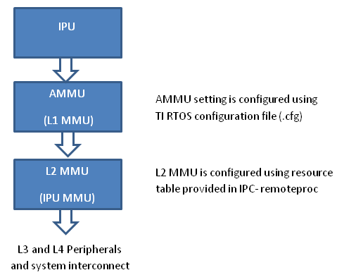
- PDK examples use addresses (0x4X000000) to peripheral registers and
use following MMU setting
- L2 MMU uses default 1:1 Mapping
- AMMU configuration translates physical 0x4X000000 access to logical 0x4X000000
- IPC+ Remote Proc ARM+M4 requires IPU to use logical address
(0x6X000000) and uses following MMU setting
- L2 MMU is configured such that MMU translates 0x6X000000 access to addresss 0x4X000000
- AMMU is configured for 1:1 mapping 0x6X000000 and 0x6X000000
Therefore after integrating IPC with PDK drivers, it is recommended that the alias addresses are used to access peripherals and PRCM registers. This requires changes to the addresses used by PDK drivers and in application code.
The following changes were then made to the IPU application source code:
Add UART_soc.c file to the project and modify the base addresses for all IPU UART register instance in the UART_HwAttrs to use alias addresses:
#ifdef _TMS320C6X
CSL_DSP_UART3_REGS,
OSAL_REGINT_INTVEC_EVENT_COMBINER,
#elif defined(__ARM_ARCH_7A__)
CSL_MPU_UART3_REGS,
106,
#else
(CSL_IPU_UART3_REGS + 0x20000000), //Base Addr = 0x48000000 + 0x20000000 = 0x68000000
45,
#endif
Adding custom SOC configuration also means that you should use the generic UART driver instead of driver with built in SOC setup. To do this comment the following line in .cfg:
var Uart = xdc.loadPackage('ti.drv.uart');
//Uart.Settings.socType = socType;
There is also an instance in the application code where we added pointer to PRCM registers that need to be changed as follows.
CSL_l4per_cm_core_componentRegs *l4PerCmReg =
(CSL_l4per_cm_core_componentRegs \*) 0x6a009700; //CSL_MPU_L4PER_CM_CORE_REGS;
Now, you are ready to build the firmware. After the .out is built, change the extension to .xem4 and copy it over to the location in the filesystem that is used to load M4 firmware.
Download the Full CCS Project
3.6.4. Multiple Ways of ARM-DSP Communication
OpenCL
OpenCL is a framework for writing programs that execute across heterogeneous systems, and for expressing programs where parallel computation is dispatched across heterogeneous devices. It is an open, royalty-free standard managed by Khronos consortium. On a heterogeneous SoC, OpenCL views one of the programmable cores as a host and the other cores as devices. The application running on the host (i.e. the host program) manages execution of code (kernels) on the device and is also responsible for making data available to the device. A device consists of one or more compute units. On the ARM and DSP SoCs, each C66x DSP is a compute unit. The OpenCL runtime consists of two components: (1) An API for the host program to create and submit kernels for execution and (2) A cross-platform language for expressing kernels – OpenCL C – which is based on C99 C with some additions and restrictions OpenCL supports both data parallel and task parallel programming paradigms. Data parallel execution parallelizes the execution across compute units on a device. Task parallel execution enables asynchronous dispatch of tasks to each compute unit. For more info, please refer to OpenCL User’s Guide
Use Cases
- Offload computation from ARM running Linux or RTOS to the DSPs
Examples
Please see OpenCL examples
Benefits
- Easy porting between devices
- No need to understand memory architecture
- No need to worry about MPAX and MMU
- No need to worry about coherency
- No need to build/configure/use IPC between ARM and DSP
- No need to be an expert in DSP code, architecture, or optimization
Drawbacks
- Don’t have control on system memory layout, etc. to handle optimize DSP code
DCE (Distributed Codec Engine)
DCE Framework provides an easy way for users to write applications on devices, such as AM57xx, having hardware accelerators for image and video. It eanbles and provides remote access to hardware acceleration for audio and video encoding and decoding on the slave cores. The ARM user space GStreamer based multimedia application uses GStreamer library to load and interface with TI GStreamer plugin which handles all the details specific to use of the hardware accelerator. The plugin interfaces libdce module that provides the ARM user space API. Libdce uses RPMSG framework on the ARM which communicates to the counterpart on the slave core. On the slave core, it uses Codec engine and Frame Component for the video/image codec processing on IVA.
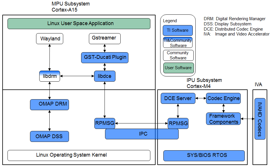
Overview of the Multimedia Software Stack using DCE AM57xx as an example has the following accelerators
- Image and Video Accelerator (IVA)
- Video Processing Engine (VPE)
- C66x DSP cores for offloading certain image/video and/or voice/audio processing
Users can leverate open source elements that provide functionality such as AVI stream demuxing, and audio codec, etc. These along with the ARM based GStreamer plugins in TI’s Processor Linux SDK provide the abstracts for the accelerator offload.
In AM57xx, the hardware accelerators are capable of the following
- IVA for multimedia enconding and decoding
- Video Decode: H264, MPEG4, MPEG2, and VC1
- video Encode: H264, and MPEG4
- Image Decode: MJPEG
- VGE for video operations such as scaling, color space conversion, and
deinterlacing of the following formats:
- Supported Input formats: NV12, YUYV, UYVY
- Supported Output formats: NV12, YUYV, UYVY, RGB24, ARGB24, and ABGR24
- DSP for offloading signal processing
- Sample Image Processing Kernels integrated in the DSP gstreamer plugin: Median2x2, Median3x3, Sobel3x3, Conv5x5, Canny
For more info, please refer to the DCE Developer’s Guide or DCE for Multimedia
Use Cases
- audio/video or proprietary codecs processing offload to slave core
Examples
- Please see sample application
Benefits
- Accelerated multimedia codec processing
- Simplifies the development of multimedia application when interfacing with Gstreamer and TI Gstreamer plugin
Drawbacks
- Not suitable for non-codec algorithm
- Need work to add new codec algorithm
- Need knowledge of DSP programming
Big Data IPC
Big Data is a special use case of TI IPC implementation for High Performance Computing applications and other Data intensive applications which often require passing of big data buffers between the multi-core processors in an SoC. The Big Data IPC provides a high level abstraction to take care of address translation and Cache sync on the big data buffers
Use Cases
- Message/Data exchange for size greater than 512 bytes between ARM and DSP
Examples
- Please see Big Data IPC example
Benefits
- Capable of handling data greater than 512 bytes
Drawbacks
- Need knowledge of DSP memory architecture
- Need knowledge of DSP configuration and programming
- TI proprietary API
IPC
Inter-Processor Communication (IPC) is a set of modules designed to faciliate inter-process communication. The communication includes message passing, streams, and linked lists. The modules provides services and functions which can be used for communication between ARM and DSP processors in a multi-processor environment.
- IPC Module initialized the various subsystems of IPC and synchronizes multiple processors.
- MessageQ Module supports the structured sending and receiving of variable length messages.
- ListMP Module is a linked-list based module designed to provide a mean of communication between different processors. It uses shared memory to provide a way for multiple processors to share, pass or store data buffers, messages,
or state information.
- HeapMP Module provides 3 types of memory management, fixed-size buffers, multiple different fixed-size buffers, and variable-size buffers.
- GateMP Module enforces both local and remote context protection through its instance.
- NOtify Module manages the multiplexing/demultiplexing of software interrupts over hardware interrupts.
- SharedRegion Module is designed to be used in a multi-processor environment where there are memory regions that are shared and accessed across different processors.
- List Module provides support for creating doubly-linked lists of objects
- MultiProc Module centralizes processor ID management into one module in a multi-processor environment.
- NameServer Module manages local name/value pairs which enables an application and other modules to sotre and retrieve values based on a name.
User Cases
- Message/Data exchange between ARM and DSP
Examples
- Please see IPC Examples
Benefits
- suitable for those who are familiar with DSP programming
- DSP code optimization
Drawbacks
- Need knowledge of DSP memory architecture
- Need knowledge of DSP configuration and programming
- message size is limited to 512 bytes
- TI proprietary API
Pros and Cons
| Pros | Cons | |
|---|---|---|
| OpenCL | Easy porting No DSP programming Standard OpenCL APIs | Customer don’t have control over memory layout etc. to handle optimize DSP code |
| DCE | Accelerated multimedia codec handling Simplifies development when interfacing with GStreamer | Not meant for non-codec algorithms Need work to add new codec algorithms Codec like APIs Require knowledge of DSP programming |
| Big Data | Full control of DSP configuration Capable of DSP code optimization Not limited to the 512 byte buffer size Same API supported on multiple TI platforms | Need to know memory architecture Need to know DSP configuration and programming TI proprietary API |
| IPC | Full control of DSP configuration Capable of DSP code optimization Same API supported on multiple TI platforms | Need to know memory architecture Need to know DSP configuration and programming Limited to small messages (less than 512 bytes) TI proprietary API |
Decision Making
The following simple flow chart is provided as a reference when making decision on which methods to use for ARM/DSP communication. Hardware capability also need to be considered in the decision making process, such as if Image and Video Accelerator exists when using DCE.
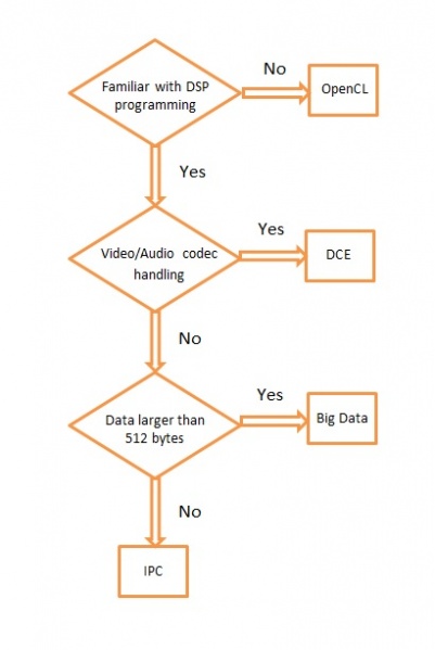
3.7. CMEM
Introduction
CMEM is an API (Reference Guide) and library for managing one or more blocks of physically contiguous memory. It also provides address translation services (e.g. virtual to physical translation) and user-mode cache management APIs. This physically contiguous memory is useful as data buffers that will be shared with another processor (e.g. for the DSP on an OMAP3) or a hardware accelerator/DMA (e.g. used by codecs on a DM365)
Using its pool-based configuration, CMEM enables users to avoid memory fragmentation, and ensures large physically contiguous memory blocks are available even after a system has been running for very long periods of time.
It was originally developed for the DM644x, and has been ported to several Operating Systems (e.g. Linux, WinCE, QNX, Nucleus, Green Hills Integrity, and others). Although generally associated with Codec Engine, it has no dependency on Codec Engine and can be used on its own.
It’s currently distributed as a component in the Linux Utils and WinCE Utils products, which may be included in various Linux and WinCE based SDKs.
Development
CMEM is a component of Linux Utils, and is actively being developed in the publicly maintained, TI-hosted ‘ludev’ git repository - https://git.ti.com/ipc/ludev. The Linux Utils development process is documented here, patches are welcome!
Configuration
Linux Configuration
CMEM configuration can be done in 2 ways either through device tree soruce file (DTS) or command line when installing cmemk.ko driver using insmod command.
DTS Configuration
The CMEM configuration can be defined in the DTS file. Take AM57xx CMEM configuration as an example which is defined in arch/arm/boot/dts/am57xx-evm-cmem.dtsi.
/ {
reserved-memory {
#address-cells = <2>;
#size-cells = <2>;
ranges;
cmem_block_mem_0: cmem_block_mem@a0000000 {
reg = <0x0 0xa0000000 0x0 0x0c000000>;
no-map;
status = "okay";
};
cmem_block_mem_1_ocmc3: cmem_block_mem@40500000 {
reg = <0x0 0x40500000 0x0 0x100000>;
no-map;
status = "okay";
};
};
cmem {
compatible = "ti,cmem";
#address-cells = <1>;
#size-cells = <0>;
#pool-size-cells = <2>;
status = "okay";
cmem_block_0: cmem_block@0 {
reg = <0>;
memory-region = <&cmem_block_mem_0>;
cmem-buf-pools = <1 0x0 0x0c000000>;
};
cmem_block_1: cmem_block@1 {
reg = <1>;
memory-region = <&cmem_block_mem_1_ocmc3>;
};
};
};
There are 2 memory blocks reserved, one in DDR starting at 0xa0000000 of size 0x0c000000. The other reserved memory block is in MSMC at 0x40500000 of size 0x100000. There are 2 CMEM blocks configuration. The first CMEM block is from DDR area and has 1 buffer in the pool of size 0x0c000000. The 2nd CMEM block is from OCMC area.
The CMEM buffer pool allocation can be viewed at run time
root@am57xx-evm:~# cat /proc/cmem
Block 0: Pool 0: 1 bufs size 0xc000000 (0xc000000 requested)
Pool 0 busy bufs:
Pool 0 free bufs:
id 0: phys addr 0xa0000000
Command Line Configuration
CMEM Linux configuration through command line is done when installing the cmemk.ko driver, typically done using the insmod command. The cmemk.ko driver accepts command line parameters for configuring the physical memory to reserve and how to carve it up.
The following is an example of installing the cmem kernel module:
/sbin/insmod cmemk.ko pools=4x30000,2x500000 phys_start=0x0 phys_end=0x3000000
- phys_start and phys_end must be specified in hexadecimal format
- pools must be specified using decimal format (for both number and size), since using hexadecimal format would visually clutter the specification due to the use of “x” as a token separator
This particular command creates 2 pools. The first pool is created with 4 buffers of size 30000 bytes and the second pool is created with 2 buffers of size 500000 bytes. The CMEM pool buffers start at 0x0 and end at 0x3000000 (max).
Pool buffers are aligned on a module-dependent boundary, and their sizes are rounded up to this same boundary. This applies to each buffer within a pool. The total space used by an individual pool will therefore be greater than (or equal to) the exact amount requested in the installation of the module.
The poolid used in the driver calls would be 0 for the first pool and 1 for the second pool.
Pool allocations can be requested explicitly by pool number, or more generally by just a size. For size-based allocations, the pool which best fits the requested size is automatically chosen.
For more details on CMEM configuration, please find info in [Linux ProcSDK]/board_support/extra-drivers/cmem-mod-(version+commit_ID)/include/ti/cmem.h which documents CMEM user interface, or refer to the device tree binding document in board-support/extra-drivers/cmem-mod-[version]+[git-commit-id]/src/cmem/module/kernel/Documentation/device-tree/bindings/cmem/ti,cmem.txt
WinCE Configuration
Configuration of CMEM in WinCE-based environments is typically done via the registry and/or statically built into the driver (for closed systems). Here is an example for a line to be added to the MEMORY section of ‘config.bib’ of your BSP:
CMEM_DSP 89000000 02800000 RESERVED ; 40 MB
That reserves 40MB of memory for CMEM, DSPLINK, DSP code as well as DSP heap usage starting at virtual address 0x89000000. There is no distinction here between the different modules memory usage. Obviously all of them need to be configured accordingly. Registry settings for CMEM use physical start and end addresses for any defined block of pools.
Here is an example CMEM configuration registry entry in platform.reg for TI EVM3530:
;-- CMEM --------------------------------------------------------------------
IF SYSGEN_CMEM
[HKEY_LOCAL_MACHINE\Drivers\BuiltIn\CMEMK]
"Prefix"="CMK"
"Dll"="cmemk.dll"
"Index"=dword:1
; Make 7 pools available for allocation for block 0
; Make 1 pool available for allocation for block 1
"NumPools0"=dword:7
"NumPools1"=dword:0
"Block0_NumBuffers_Pool0"=dword:20
"Block0_PoolSize_Pool0"=dword:1000 ; size in bytes (hex)
"Block0_NumBuffers_Pool1"=dword:8
"Block0_PoolSize_Pool1"=dword:20000 ; size in bytes (hex)
"Block0_NumBuffers_Pool2"=dword:5
"Block0_PoolSize_Pool2"=dword:100000 ; size in bytes (hex)
"Block0_NumBuffers_Pool3"=dword:1
"Block0_PoolSize_Pool3"=dword:15cfc0 ; size in bytes (hex)
"Block0_NumBuffers_Pool4"=dword:1
"Block0_PoolSize_Pool4"=dword:3e800 ; size in bytes (hex)
"Block0_NumBuffers_Pool5"=dword:1
"Block0_PoolSize_Pool5"=dword:36ee80 ; size in bytes (hex)
"Block0_NumBuffers_Pool6"=dword:3
"Block0_PoolSize_Pool6"=dword:96000 ; size in bytes (hex)
;; "Block1_NumBuffers_Pool1"=dword:2
;; "Block1_PoolSize_Pool1"=dword:4000 ; size in bytes (hex)
; Physical start + physical end can be use to ask CMEM to map a specific
; range of physical addresses.
; This is a potential security risk. If physical start == 0 then the code
; hits a special case.
; physical end - physical start == length of allocation. In the special
; case, memory is allocated via a call to AllocPhysMem() (as shown in
; this example). MmMapIoSpace() is used to map the normal case where
; physical start != 0.
;
; physical start and end for block 0
"PhysicalStart0"=dword:85000000
"PhysicalEnd0"=dword:86000000
; physical start and end for block 1
"PhysicalStart1"=dword:0
"PhysicalEnd1"=dword:0
ENDIF SYSGEN_CMEM
;------------------------------------------------------------------------------
The CMEM driver information must also be added to the platform.bib file (or some other .bib file that gets put into ce.bib). Here is an example of the CMEM driver entry in platform.bib:
;-- CMEM ----------------------------------------------------------------------
IF SYSGEN_CMEM
cmemk.dll $(_FLATRELEASEDIR)\cmemk.dll NK SHK
ENDIF BSP_CMEM
;------------------------------------------------------------------------------
Debugging Techniques
Linux users can execute “cat /proc/cmem” to get status on the buffers and pools managed by CMEM.
There is also a debug library provided that provides tracing diagnostics during execution. XDC Config users can link in this library by adding the following to their application’s config script:
var CMEM = xdc.useModule('ti.sdo.linuxutils.cmem.CMEM');
CMEM.debug = true;
General Purpose Heaps
In CMEM 2.00, CMEM added support for a general purpose heap. Using the example above, in addition to the 2 pools, a general purpose heap block is created from which allocations of any size can be requested. Internally, allocation sizes are rounded up to a module-dependent boundary and allocation addresses are aligned either to this same boundary or to the requested alignment (whichever is greater).
The size of the heap block is the amount of CMEM memory remaining after all pool allocations. If more heap space is needed than is available after pool allocations, you must reduce the amount of CMEM memory granted to the pools.
The main disadvantage to using heap(s) over pools is fragmentation. After several sequences of codec creation/deletion, in different orders, with possibly different create() params, you may end up fragmenting your heap and being unable to acquire a requested memory block - possibly resulting in a codec creation failure.
Typically, during development, users will use CMEM with heap-based memory, as heap usage requires very little configuration, and users don’t know how to configure pool memory(!). In a production system, however, it’s strongly recommended that pool configuration be used to avoid memory fragmentation and confusing end user errors.
Application Cleanup
CMEM 2.23 introduced a facility to clean up unfreed buffers when an application exits, either prematurely or in a normal fashion. This facility is achieved by maintaining an “ownership” list for each allocated buffer that is inspected upon closing a device driver instance. During this inspection all allocated buffers are checked, and when it is determined that the closing process is on the ownership list of an allocated buffer, the process is removed from the list. If this causes the list to become empty the associated buffer is actually freed, otherwise it is maintained in the allocated state on behalf of other owners. A side-effect of this model is that only a buffer “owner” is allowed to free the buffer.
In order to facilitate multiple owners of an allocated buffer, a new set of APIs was introduced:
void *CMEM_registerAlloc(unsigned long physp);
int CMEM_unregister(void *ptr, CMEM_AllocParams *params);
CMEM_registerAlloc() takes a buffer physical address as input (achieved through CMEM_getPhys()) and returns a fresh virtual address that is mapped to that buffer, while also adding the calling process to the ownership list. CMEM_unregister() is equivalent to CMEM_free() and releases ownership of the buffer (as well as freeing it if all owners have released the buffer).
In CMEM 2.24, ownership is established on a per-process (and per-thread) basis. This detail becomes important when using CMEM in multiple threads of a given process - if one thread allocates a CMEM buffer and a separate thread of the same process is responsible for freeing that buffer, the “freeing” thread will not be allowed to free the buffer since it is not on the ownership list.
CMEM 2.24.01 changes the ownership policy to be based on the calling process’ file descriptor instead of the calling process’ process descriptor. This facilitates thread-based sharing of buffers, allowing any thread within a process to free a buffer that was allocated by a different thread within the same process, since threads within a process all use the same file descriptor.
Linux CMA Support
CMEM 4.00 added the ability to leverage the Linux kernel’s CMA feature. CMA supports a “global” memory pool, as well as device-specific memory - CMEM provides the facilities to allocate from either type of CMA pool.
CMA also defines the carveout area of the physical location where the DSP code/data will actually reside. The DSP carveouts are defined in the dts file. For example the AM57xx EVM, it is linux/arch/arm/boot/dts/am57xx-beagle-x15-common.dtsi.
dsp1_cma_pool: dsp1_cma@99000000 {
compatible = "shared-dma-pool";
reg = <0x0 0x99000000 0x0 0x4000000>;
reusable;
status = "okay";
};
dsp2_cma_pool: dsp2_cma@9f000000 {
compatible = "shared-dma-pool";
reg = <0x0 0x9f000000 0x0 0x800000>;
reusable;
status = "okay";
};
Note that using CMEM to allocate from CMA-based memory is an additional feature. You can continue to use CMEM to manage memory carveouts as well.
Android CMA Support
Build Environment Setup
First download an unzip the latest Linux utils(4.00.01.08) zip file. The file products.mak (at the top level of this tree) contains two definitions used by the build subsystem:
KERNEL_INSTALL_DIR - The base directory of your Linux kernel source tree
TOOLCHAIN_PREFIX - the 'prefix' for the GNU ARM codegen tools
The TOOLCHAIN_PREFIX can contain the full path of the codegen tools, ending with the tool prefix, i.e.:
TOOLCHAIN_PREFIX=/db/toolsrc/library/vendors2005/cs/arm/arm-2008q1-126/bin/arm-none-linux-gnueabi-
or it can be just the tool prefix if your shell’s $PATH contains your codegen’s ‘bin’ directory:
TOOLCHAIN_PREFIX=arm-none-linux-gnueabi-
where your $PATH contains:
/db/toolsrc/library/vendors2005/cs/arm/arm-2008q1-126/bin
For example, below is the setup environment which is validated
TOOLCHAIN_LONGNAME = arm-eabi
TOOLCHAIN_INSTALL_DIR = /home/(user)/mydroid/prebuilts/gcc/linux-x86/arm/arm-eabi-4.7
KERNEL_INSTALL_DIR =/home/(user)/kernel/android-3.8
Now move to the src/cmem/module directory to run “make clean” and then “make”.
Building Test Binaries
From the downloaded and installed linux utils base directory run the below commands,
Note: Any non-android toolchain should work and don’t forget to export the toolchain path(until the bin folder) to PATH environment variable.
export ARCH=arm
export CROSS_COMPILE=arm-linux-gnueabihf
./configure --disable-shared --host=arm-linux-gnueabihf --prefix=$PWD CFLAGS='--static'
Now run “make clean” and “make” to build the test binaries for android
Test Setup and Validation Process
For testing purpose we built the android kernel for mem=1200M.
Boot the system with android and then do adb push on the below mentioned files,
(linux utils base directory)/src/cmem/module/cmemk.ko to /system/lib/modules
(linux utils base directory)/src/cmem/tests/apitest to /system/bin
(linux utils base directory)/src/cmem/tests/multi_process to /system/bin
(linux utils base directory)/src/cmem/tests/translate to /system/bin
The loadable kernel module ‘cmemk.ko’ can be installed into any running system. Out of the 3 tests mentioned below Multi_Process & Translate tests have been used to validate the CMEM module’s usage of OCMC1 ram. OCMC1 ram range is 0x40300000 ~ 0x4033FFFF.
Multi Process Test
This app tries to use CMEM from multiple processes. It takes the number of processes to start as a parameter. Now load the kernel module ‘cmemk.ko’ with the below command:
% insmod cmemk.ko phys_start=0xcaf01000 phys_end=0xCB601000 pools=4x1000 phys_start_1=0xCB601000 phys_end_1=0xCB701000 pools_1=4x1000
(Uses DDR)
% insmod cmemk.ko phys_start=0x40300000 phys_end=0x4033FFFF pools=4x500 phys_start_1=0x4033FFFF phys_end_1=0x4037ffff pools_1=4x500 allowOverlap=1
(Uses OCMC1, for this rebuild the Translate Test app with macro BUFFER_SIZE = 500 at line #49 in file (linuxutils)/src/cmem/tests/multi_process.c) Now run the Multi Process test,
% multi_process 3
where 3 is the number of processes to be spawned.
Translate Test
This app tests the address translation. Now load the kernel module ‘cmemk.ko’ with the below command:
% insmod cmemk.ko phys_start=0xcaf01000 phys_end=0xCB601000 pools=1x3145728
(Uses DDR)
% insmod cmemk.ko phys_start=0x40300000 phys_end=0x4037ffff pools=1x20000 allowOverlap=1
(Uses OCMC1, for this rebuild the Translate Test app with macro BUFSIZE = 20000 at line #48 in file (linuxutils)/src/cmem/tests/translate.c) Now run the Translate test,
% translate
API Test
Tests basic API usage and memory allocation. This particular test has a limitation as it runs successfully only on kernel built with mem=120M. Now load the kernel module ‘cmemk.ko’ with the below command:
% insmod cmemk.ko phys_start=0x87800000 phys_end=0x87F00000 pools=4xBUFSIZE phys_start_1=0x87F00000 phys_end_1=0x88000000 pools_1=4xBUFSIZE
where BUFSIZE is the number of bytes you plan on passing as command line parameter to apitest. If in doubt, use a larger number as BUFSIZE denotes the maximum buffer you can allocate.Now run the Translate test, Now run the API test,
% apitest <BUFSIZE>
(e.g) With BUFSIZE=10240
% apitest 10240
CMEM FAQ
Q: Why am I’m getting this error when loading the CMEM (or other!) driver: “insmod: error inserting ‘cmemk.ko’: -1 Invalid module format”?
A: This error indicates the CMEM kernel module was built with a different Linux kernel version than the version running on the target. You need to rebuild CMEM against the kernel running on your target. Q: Can CMEM_getPhys() be used to translate any virtual address to its physical address?
A: In theory, “yes”. However, sometime after Linux version 2.6.10 the CMEM kernel module get_phys() function stopped working for kernel addresses. A new get_phys() was provided to work with newer kernels, but it was discovered that this new one didn’t correctly translate non-direct-mapped kernel addresses, so code was added to CMEM to save the lower/upper bounds of the CMEM blocks’ kernel addresses, and manually look for those in get_phys() before trying more general methods of translation. So, in short, CMEM’s get_phys() doesn’t handle non-direct-mapped kernel addresses except the ones that correspond to CMEM’s managed memory block(s). Q: How does CMEM relate to DSPLink’s POOL feature?
A: Though they provide overlapping features, they are independent, and each has unique features.
- CMEM
- CMEM can be used on systems without a remote DSP slave (e.g. DM365 codecs require physically contiguous memory when using HW accelerators)
- CMEM buffers can be cached
- CMEM blocks support fixed size pools (no fragmentation) as well as heaps (easier to use)
- CMEM configuration doesn’t require a rebuild (they’re provided as insmod params)
- POOL
- POOL buffers can be allocated on one processor and freed on another
Q: In Linux, how do I set aside the memory carveout that CMEM uses?
A: The memory carveout used by CMEM must not be in use by Linux else an error will occur during module loading (i.e., insmod/modprobe). There are two simple methods for defining CMEM’s memory carveout:
- kernel command line
This method involves the kernel command line issued from u-boot. When booting Linux, one may restrict the memory available to Linux by specifying physical memory blocks for Linux to use: “mem=#[KMG]@0xXXXXXXXX” e.g.: mem=128M@0x80000000 mem=256M@0x90000000 which grants the memory at 0x80000000 -> 0x88000000 and 0x90000000 -> 0xa0000000 to Linux, leaving the CMEM memory carveout as 128MB at 0x88000000 (0x88000000 -> 0x90000000). Without a “mem=” entry on the command line, Linux will use all available memory.
- removal via machine’s “.reserve” function
This method involves modifying a machine’s .reserve function to remove a block of memory from Linux. For example, for the Vayu architecture, the file arch/arm/mach-omap2/common.c contains a function named dra7_reserve() which is assigned to the machine .reserve function in arch/arm/mach-omap2/board-generic.c. Adding the following C statement to dra7_reserve() accomplishes the same memory carveout as specified in 1) above: memory_remove(0x88000000, 0x08000000); The CMEM memory carveout can either precede, overlap, or succeed the Linux memory. For the case where it precedes or overlaps, don’t forget to specify “allowOverlap=1” on the cmemk.ko insmod/modprobe command, else the module loading will fail. For both cases above, you would load cmemk.ko as follows: % modprobe cmemk.ko phys_start=0x88000000 phys_end=0x90000000 allowOverlap=1 pools=... The advantage for method 1) is that the CMEM memory carveout can be specified to be anywhere by the system integrator without changing the kernel, with a disadvantage of having to document this carveout specification along with potential error in doing so. The advantage of method 2) is that a given kernel image will always properly create the carveout for CMEM without any intervention by the system integrator, with a disadvantage of not being moveable without changing/rebuilding the kernel. Q: Why CMEM failed in physical address > 32bits?
A: The user space application need to be compiled with “–D_FILE_OFFSET_BITS=64” to allow physical addresses > 32 bits. |
Licensing
In CMEM 2.00, the CMEM Linux release is LGPL v2 for the user mode lib and GPL v2 for the kernel mode driver.
In CMEM 2.21, the Linux user mode library licensing changed from LGPL to BSD. The Linux kernel mode driver continued to be GPL v2.
3.8. Graphics and Display
3.8.1. Introduction
TI SOCs like AM355x, AM437x and AM57xx are enabled with 3D cores, capable of accelerating 3D operations with dedicated hardware. The dedicated hardware is based on SGX series of devices from Imagination Technologies. The graphics cores only accelerate graphics operations, and do not perform video decode operations. For video acceleration, refer to respective Technical Reference Manuals for the SOCs.
Below table lists the various TI families supported by this SDK, and the SGX core information
| TI SOC Name | SGX Core | SGX Core Revision | Max SGX Core Frequency (MHz) |
|---|---|---|---|
| AM335x | SGX530 | 1.2.5 | 200 |
| AM437x | SGX530 | 1.2.5 | 200 |
| AM57xx | SGX544 | 1.1.6 | 532 |
Table: TI System on Chips, and SGX cores
Since the 3D accelerator (SGX core) is outside the ARM core, the Graphics drivers run on ARM core, and contain OS specific driver code to memory map the SGX core and program the engine from the OS running on the ARM core. The current version of SGX DDK provides OpenGLES2.0 and EGL libraries which are used by the graphics stacks in Processor SDK, such as QT5 and Wayland/Weston, Mesa-EGL based apps are currently not supported.
This Processor SDK Graphics and Display page will cover the following topics:
- Software architecture of Graphics
- Instructions on how to run graphics demos
- Instructions on how to run PVR tools
- Instructions on how to run DSS application
- Migration Guide
- AM3 Beagle Bone Black Board Configuration
- SGX Debugging Tips
- SoC Performance Monitoring Tools
3.8.2. Software Architecture
The picture below shows the software architecture of Graphics in Processor SDK.
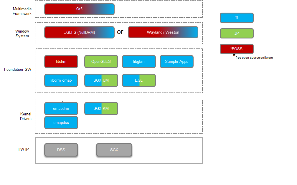
3.8.3. Graphics Demos Available via Matrix
The following 3D Graphics demos are available via Matrix. The table below provides a list of these demos, with a brief description.
| Demo Name | Details |
| ChameleonMan | This demo shows a matrix skinned character in combination with bump mapping. |
| CoverFlow | This is a demonstration of a coverflow style effect |
| ExampleUI | This demo shows how to efficiently render sprites and interface elements. |
| Navigation | This is a demonstration of how to implement rendering algorithms for Navigation software. |
| Kmscube | This demo shows how to render and display multi-colored spinning cube |
Note that some of the 3D Graphics demos are from Imagination’s PowerVR SDK.
3.8.4. Graphics Demos from Command Line
The graphics driver and userspace libraries and binaries are distributed along with the SDK.
Graphic demos can also run from command line. In order to do so, exit Weston by pressing Ctrl-Alt-Backspace from the keyboard which connects to the EVM. Then, if the LCD screen stays in “Please wait...”, press Ctrl-Alt-F1 to go to the command line on LCD console. After that, the command line can be used from serial console, SSH console, or LCD console.
Please make sure the board is connected to at least one display before running these demos.
3.8.4.1. Finding Connector ID
Note: Most of the applications used in the Demos would require the user to pass a connector id. A connector id is a number that is assigned to each of the display devices connected to the system. To get the list of the display devices connected and the corresponding connector id one can use the modetest application (shipped with the file system) as mentioned below:
target # modetest
Look for the display device for which the connector ID is required - such as HDMI, LCD etc.
Connectors:
id encoder status type size (mm) modes encoders
4 3 connected HDMI-A 480x270 20 3
modes:
name refresh (Hz) hdisp hss hse htot vdisp vss vse vtot)
1920x1080 60 1920 2008 2052 2200 1080 1084 1089 1125 flags: phsync, pvsync; type: preferred, driver
...
16 15 connected unknown 0x0 1 15
modes:
name refresh (Hz) hdisp hss hse htot vdisp vss vse vtot)
800x480 60 800 1010 1040 1056 480 502 515 525 flags: nhsync, nvsync; type: preferred, driver
Usually, LCD is assigned 16 (800x480), and HDMI is assigned 4 (multiple resolutions).
3.8.4.2. Finding Plane ID
To find the Plane ID, run the modetest command:
target # modetest
Look for the section called Planes. (Sample truncated output of the Planes section is given below)
Planes:
id crtc fb CRTC x,y x,y gamma size
19 0 0 0,0 0,0 0
formats: RG16 RX12 XR12 RA12 AR12 XR15 AR15 RG24 RX24 XR24 RA24 AR24 NV12 YUYV UYVY
props:
...
20 0 0 0,0 0,0 0
formats: RG16 RX12 XR12 RA12 AR12 XR15 AR15 RG24 RX24 XR24 RA24 AR24 NV12 YUYV UYVY
props:
...
3.8.4.3. kmscube
Run kmscube on default display:
target # kmscube
Run kmscube on secondary display:
target # kmscube -c <connector-id>
target # kmscube -c 16 #For example, the connector id for secondary display is 16.
Run kmscube on all connected displays (LCD & HDMI):
target # kmscube -a
3.8.4.4. Wayland/Weston
The supported Wayland/Weston version brings in the multiple display support in extended desktop mode and the ability to drag-and-drop windows from one display to the other.
To launch weston, do the following:
On target console:
target # unset WAYLAND_DISPLAY
On default display:
target # weston --tty=1 --connector=<default connector-id>
On secondary display:
target # weston --tty=1 --connector=<secondary connector-id>
On all connected displays (LCD and HDMI):
target # weston --tty=1
The user can change the screensaver timeout using a command line option
--idle-time=<number of seconds>
For example, to set timeout of 10 minutes and weston configured to display on all connectors, use the below command:
weston --tty=1 --idle-time=600
To disable the screen timeout and to configure weston configured to display on all connectors, use the below command:
weston --tty=1 --idle-time=0
If you face any issues with the above procedure, please refer GLSDK_FAQs#Unable_to_run_Weston_on_the_GLSDK_release for troubling shooting tips.
The filesystem comes with a preconfigured weston.ini file which will be located in
/etc/weston.ini
Running weston clients
# /usr/bin/weston-flower
# /usr/bin/weston-clickdot
# /usr/bin/weston-cliptest
# /usr/bin/weston-dnd
# /usr/bin/weston-editor
# /usr/bin/weston-eventdemo
# /usr/bin/weston-image /usr/share/weston/terminal.png
# /usr/bin/weston-resizor
# /usr/bin/weston-simple-egl
# /usr/bin/weston-simple-shm
# /usr/bin/weston-simple-touch
# /usr/bin/weston-smoke
# /usr/bin/weston-info
# /usr/bin/weston-terminal
Running multimedia with Wayland sink
The GStreamer video sink for Wayland is the waylandsink. To use this video-sink for video playback:
target # gst-launch-1.0 playbin uri=file://<path-to-file-name> video-sink=waylandsink
Exiting weston
Terminate all Weston clients before exiting Weston. If you have invoked Weston from the serial console, exit Weston by pressing Ctrl-C.
It is also possible to invoke Weston from the native console, exit Weston by using pressing Ctrl-Alt-Backspace.
3.8.4.5. Using IVI shell feature
The SDK also has support for configuring weston ivi-shell. The default shell that is configured in the SDK is the desktop-shell.
To change the shell to ivi-shell, the user will have to add the following lines into the /etc/weston.ini.
To switch back to the desktop-shell can be done by commenting these lines in the /etc/weston.ini (comments begin with a ‘#’ at the start of line).
[core]
shell=ivi-shell.so
[ivi-shell]
ivi-module=ivi-controller.so
ivi-input-module=ivi-input-controller.so
After the above configuration is completed, we can restart weston by running the following commands
target# /etc/init.d/weston stop
target# /etc/init.d/weston start
NOTE: When weston starts with ivi-shell, the default background is black, this is different from the desktop-shell that brings up a window with background.
With ivi-shell configured for weston, wayland client applications use ivi-application protocol to be managed by a central HMI window management. The wayland-ivi-extension provides ivi-controller.so to manage properties of surfaces/layers/screens and it also provides the ivi-input-controller.so to manage the input focus on a surface.
Applications must support the ivi-application protocol to be managed by the HMI central controller with an unique numeric ID.
Some important references to wayland-ivi-extension can be found at the following links:
- https://at.projects.genivi.org/wiki/display/WIE/01.+Quick+start
- https://at.projects.genivi.org/wiki/display/PROJ/Wayland+IVI+Extension+Design
Running weston’s sample client applications with IVI shell
All the sample client applications in the weston package like weston-simple-egl, weston-simple-shm, weston-flower etc also have support for ivi-shell. The SDK includes the application called layer-add-surfaces which is part of the wayland-ivi-extension. This application allows the user to invoke the various functionalities of the ivi-shell and control the applications.
The following is an example sequence of commands and the corresponding effect on the target.
After launching the weston with the ivi-shell, please run the below sequence of commands:
target# weston-simple-shm &
At this point nothing is displayed on the screen, some additional commands are required.
target# layer-add-surfaces 0 1000 2 &
This command creates a layer with ID 1000 and to add maximum 2 surfaces to this layer on the screen 0 (which is usually the LCD).
At this point, the user can see weston-simple-shm running on LCD. This also prints the numericID (surfaceID) to which client’s surface is mapped as shown below:
CreateWithDimension: layer ID (1000), Width (1280), Height (800)
SetVisibility : layer ID (1000), ILM_TRUE
layer: 1000 created
surface : 10369 created
SetDestinationRectangle: surface ID (10369), Width (250), Height (250)
SetSourceRectangle : surface ID (10369), Width (250), Height (250)
SetVisibility : surface ID (10369), ILM_TRUE
layerAddSurface : surface ID (10369) is added to layer ID (1000)
Here 10369 is the number to which weston-simple-shm application’s surface is mapped.
User can launch one more client application which allows layer_add_surfaces to add second surface to the layer 1000 as shown below.
target# weston-flower &
User can control the properties of the above surfaces using LayerManagerControl as shown below to set the position, resize, rotation, opacity and visibility respectively.
target# LayerManagerControl set surface 10369 position 100 100
target# LayerManagerControl set surface 10369 destination region 150 150 300 300
target# LayerManagerControl set surface 10369 orientation <0/1/2/3> (for steps of rotation in 90 degree angles)
target# LayerManagerControl set surface 10369 opacity 0.5
target# LayerManagerControl set surface 10369 visibility 1
target# LayerManagerControl help
The help option prints all possible control operations with the LayerManagerControl binary, please refer to the available options.
Running QT applications with IVI shell
To run the QT application withs ivi shell, set the QT_WAYLAND_SHELL_INTEGRATION environment variable to ivi-shell.
- QT_WAYLAND_SHELL_INTEGRATION=ivi-shell
IMG PowerVR Demos
The Processor SDK filesystem comes packaged with example OpenGLES applications. The examples can be invoked using the below commands.
target # /usr/bin/SGX/demos/Raw/OGLES2Coverflow
target # /usr/bin/SGX/demos/Raw/OGLES2ChameleonMan
target # /usr/bin/SGX/demos/Raw/OGLES2ExampleUI
target # /usr/bin/SGX/demos/Raw/OGLES2Navigation
After you see the output on the display interface, hit q to terminate the application.
3.8.5. Using the PowerVR Tools
The suite of PowerVR Tools is designed to enable rapid graphics application development. It targets a range of areas including asset exporting and optimization, PC emulation, prototyping environments, on-line and off-line performance analysis tools and many more. Please refer to https://community.imgtec.com/developers/powervr/graphics-sdk/ for additional details on the tools and detailed documentation.
The target file system includes a subset of PowerVR tools such as PVRScope and PVRTrace recorder libraries from Imagination PowerVR SDK to profile and trace SGX activities. In addition, it also includes PVRPerfServerDeveloper tool.
3.8.5.1. PVRTune
The PVRTune utility is a real-time GPU performance analysis tool. It captures hardware timing data and counters which facilitate the identification of performance bottlenecks. PVRPerfServerDeveloper should be used along with the PVRTune running on the PC to gather data on the SGX loading and activity threads. You can invoke the tool with the below command:
target # /opt/img-powervr-sdk/PVRHub/PVRPerfServer/PVRPerfServerDeveloper
3.8.5.2. PVRTrace
The PVRTrace is an OpenGL ES API recording and analysis utility. PVRTrace GUI provides off-line tools to inspect captured data, identify redundant calls, highlight costly shaders and many more. The default filesystem contains helper scripts to obtain the PVRTrace of the graphics application. This trace can then be played back on the PC using the PVRTrace Utility.
To start tracing, use the below commands as reference:
target # cp /opt/img-powervr-sdk/PVRHub/Scripts/start_tracing.sh ~/.
target # ./start_tracing.sh <log-filename> <application-to-be-traced>
Example:
target # ./start_tracing.sh westonapp weston-simple-egl
The above command will do the following:
- Setup the required environment for the tracing
- Create a directory under the current working directory called pvrtrace
- Launch the application specified by the user
- Start tracing the PVR Interactions and record the same to the log-filename
To end the tracing, user can invoke the Ctrl-C and the trace file path will be displayed.
The trace file can then be transferred to a PC and we can visualize the application using the host side PVRTrace utility. Please refer to the link at the beginning of this section for more details.
3.8.6. Running DSS application
DSS applications are omapdrm based. These will demonstrate the clone mode, extended mode, overlay window, z-order and alpha blending features. To demonstrate clone and extended mode, HDMI display must be connected to board. Application requires the supported mode information of connected displays and plane ids. One can get these information by running the modetest application in the filesystem.
target # modetest
Running drmclone application
This displays same test pattern on both LCD and HDMI (clone). Overlay window also displayed on LCD. To test clone mode, execute the following command:
target # drmclone -l <lcd_w>x<lcd_h> -p <plane_w>x<plane_h>:<x>+<y> -h <hdmi_w>x<hdmi_h>
e.g.: target # drmclone -l 1280x800 -p 320x240:0+0 -h 640x480
We can change position of overlay window by changing x+y values. eg. 240+120 will show @ center
Running drmextended application
This displays different test pattern on LCD and HDMI. Overlay window also displayed on LCD. To test extended mode, execute the following command:
target # drmextended -l <lcd_w>x<lcd_h> -p <plane_w>x<plane_h>:<x>+<y> -h <hdmi_w>x<hdmi_h>
e.g.: target # drmextended -l 1280x800 -p 320x240:0+0 -h 640x480
Running drmzalpha application
Z-order:
It determines, which overlay window appears on top of the other.
Alpha Blend:
It determines transparency level of image as a result of both global alpha & pre multiplied alpha value.
- Pre multipled alpha value: 0 or 1
- 0 - source is not premultiply with alpha1 - source is premultiply with alpha
To test drmzalpha, execute the following command:
target # drmzalpha -s <crtc_w>x<crtc_h> -w <plane1_id>:<z_val>:<glo_alpha>:<pre_mul_alpha> -w <plane2_id>:<z_val>:<glo_alpha>:<pre_mul_alpha>
e.g.: target # drmzalpha -s 1280x800 -w 19:1:255:1 -w 20:2:255:1
3.8.7. QT Graphics Framework
Qt is a powerful C++ toolkit for writing cross-platform graphics applications, enabling a single code base to run predictably and perform well on Windows and embedded platforms,
Please refer https://www.qt.io/ for additional details on Qt.
The PSDK target file system includes the pre-built Qt libraries under /usr/lib and a rich set of QT demo applications under /usr/share/qt5/examples. A small subset of QT demo applications such as Calculator and Animatedtiles can also be invoked through Matrix.
QT QPA
The QT5 within PSDK is prebuilt with Wayland enabled and therefore wayland-egl is the default QPA. Hence all QT applications should be run on top of Weston. To run QT application without Weston, the user can use “- platform” option to specify the desired QPA as “linuxfb” or “eglfs”.
3.8.8. Migration from prior releases
3.8.8.1. from Processor SDK 1.x to 2.x for AM3, AM4
The SGX driver has been enhanced to support DRM based Full Window Display in processor SDK 2.0 and the FBdev based Full Window modes are no longer supported. The System startup and most of the Graphics applications are backward-compatible except with the following changes.
Window System Libraries
The FBdev based Full Screen window systems are no longer supported:
- libpvrPVR2D_FRONTWSEGL.so (for direct writes to FrameBuffer - FRONT mode of operation - directly writes to FrameBuffer without waiting for vsync - fastest mode of operation)
- libpvrPVR2D_FLIPWSEGL.so (for VSync synchronised writes to Framebuffer - slower, but avoids tearing)
- libpvrPVR2D_BLITWSEGL.so (for direct writes to back-buffer, which later gets written to *FrameBuffer with sync)
Instead the DRM based Full Screen window system are provided:
- libpvrDRMWSEGL_FRONT.so (for direct writes to DRM FrameBuffer - FRONT mode of operation - directly writes to FrameBuffer without waiting for vsync - fastest mode of operation)
- libpvrDRMWSEGL.so (for VSync synchronised writes to DRM Framebuffer - slower, but avoids tearing)
The window system is specified by the PVR configuration parameter WindowSystem at the PVR configuration file /etc/powervr.ini. By default, that parameter is set to libpvrDRMWSEGL_FRONT.so for nullDRM Front mode. To configure the PVR SGX to operate in nullDRM FLIP mode, edit the PVR configuration file to set the parameter WindowSystem to libpvrDRMWSEGL.so. The change will take effect when any graphic application is launched next time.
Obsolete Test Programs
The following test programs are no longer applicable and removed from the SDK file system
- /usr/bin/sgx_blit_test
- /usr/bin/sgx_flip_test
- /usr/bin/sgx_render_flip_test
- /usr/bin/sgx_render_test
3.8.8.2. from Processor SDK 2.0.0 to 2.0.x for AM4
The SGX driver has been enhanced to support DRM/WAYLAND based Multi-Window Display in processor SDK 2.0.1. The System startup and most of the Graphics applications are backward-compatible except with the following changes.
Window System Libraries
The DRM based Full Screen window systems are no longer supported:
- libpvrDRMWSEGL_FRONT.so (for direct writes to DRM FrameBuffer - FRONT mode of operation - directly writes to FrameBuffer without waiting for vsync - fastest mode of operation)
- libpvrDRMWSEGL.so (for VSync synchronised writes to DRM Framebuffer - slower, but avoids tearing)
Instead the DRM/WAYLAND based multi-window system are provided:
- libpvrws_KMS.so
- libpvrws_WAYLAND.so
The window system will be dynamically loaded by DDK based on the application use case, so that the PVR configuration parameter WindowSystem at the PVR configuration file /etc/powervr.ini is no longer used.
3.8.8.3. from Processor SDK 2.0.1 to 2.0.x for AM3/4/5
The SGX driver has been enhanced to support DRM-based Full Screen(NullDRM) and Multi-Window(Wayland) Display in processor SDK 2.0.2. The System startup and most of the Graphics applications are backward-compatible except with the following changes.
Window System Libraries
The DRM based Full Screen window system is supported:
- libpvrDRMWSEGL.so (for VSync synchronised writes to DRM Framebuffer - slower, but avoids tearing)
The DRM/WAYLAND based multi-window systems are also provided:
- libpvrGBMWSEGL.so
- libpvrws_WAYLAND.so
The window system will be dynamically loaded by DDK based on the application use case, so that the PVR configuration parameter WindowSystem at the PVR configuration file /etc/powervr.ini is no longer required.
3.8.8.4. from Processor SDK 3.1 to 3.x for AM3/4/5
The QT QPA eglfs_kms, which supports multiple screens, has been enabled and used as the default eglfs platform plugin in processor SDK 3.2. To fallback to the standard single-screen eglfs plugin, issue the following instruction at the command line or add the same at the QT environment configuration file qt_env.sh at /etc/profile.d
- export QT_QPA_EGLFS_INTEGRATION=none
3.8.9. AM3 Beagle Bone Black Board Configuration
AM335x has a HW bug, chapter 3.1.1 in the errata: “The blue and red color assignments to the LCD data pins are reversed when operating in RGB888 (24bpp) mode compared to RGB565 (16bpp) mode.” Therefore, the applications need to always use either 24 or 16 bpp modes, depending on the display HW connected to the board. The default pixel format XRGB8888 of the graphics application back ends and drivers within PSDK is not supported at the AM3 Beagle Bone Black Board where it is in 16bpp mode. To enable appropriate graphics display, make the following changes at various graphics related configuration files:
- /etc/powervr.ini: add DefaultPixelFormat=RGB565
- /etc/weston.ini: add gbm-format=rgb565 at section [core]
- /etc/profile.d/qt_env.sh: add export QT_QPA_EGLFS_INTEGRATION=none
Another restriction of AM335x-based platform is that the width of display resolution must be multiple of 32. For example, 1360x768 will not work. The simple workaround is to specify the display resolution as one of the kernel boot parameters for non-Weston application and at /etc/weston.ini for Weston server. For example,
- the following commands need to be executed at boot prompt
=> setenv optargs video=HDMI-A-1:1024x768
=> saveenv
- add the HDMI-A configuration to /etc/weston.ini in a new “output” section, as shown below:
[output]
name=HDMI-A-1
mode=1024x768
3.8.10. SOC Performance monitoring tools on AM5 Devices
Introduction
The SOC Performance monitoring tools are a set of tools that are included in the default filesystem that allow the user to visualize various SOC parameters real-time on the screen. Currently, there are two tools and a suite of scripts and utilities to use them.
- soc-performance-monitor
- soc-ddr-bw-visualize
Both these applications are Wayland applications and need to be invoked after running Weston.
These tools bring in the capability to visualize the following:
- DDR BW Utilization #. Overall DDR BW Usage #. Split of the traffic between the two EMIF’s #. A real time “top” like functionality that depicts the list of “Top 6” initiators generating the traffic.
- Voltage of the various rails
- Frequency of the various cores
- Temperature (read from on die temperature sensors)
- CPU Load information of the various processor cores including the GPU and DSP.
- Boot time results (requires rebuild of u-boot and kernel), refer instructions below.
- Power plot (Will be available soon. Note that this requires board modification on the EVM)
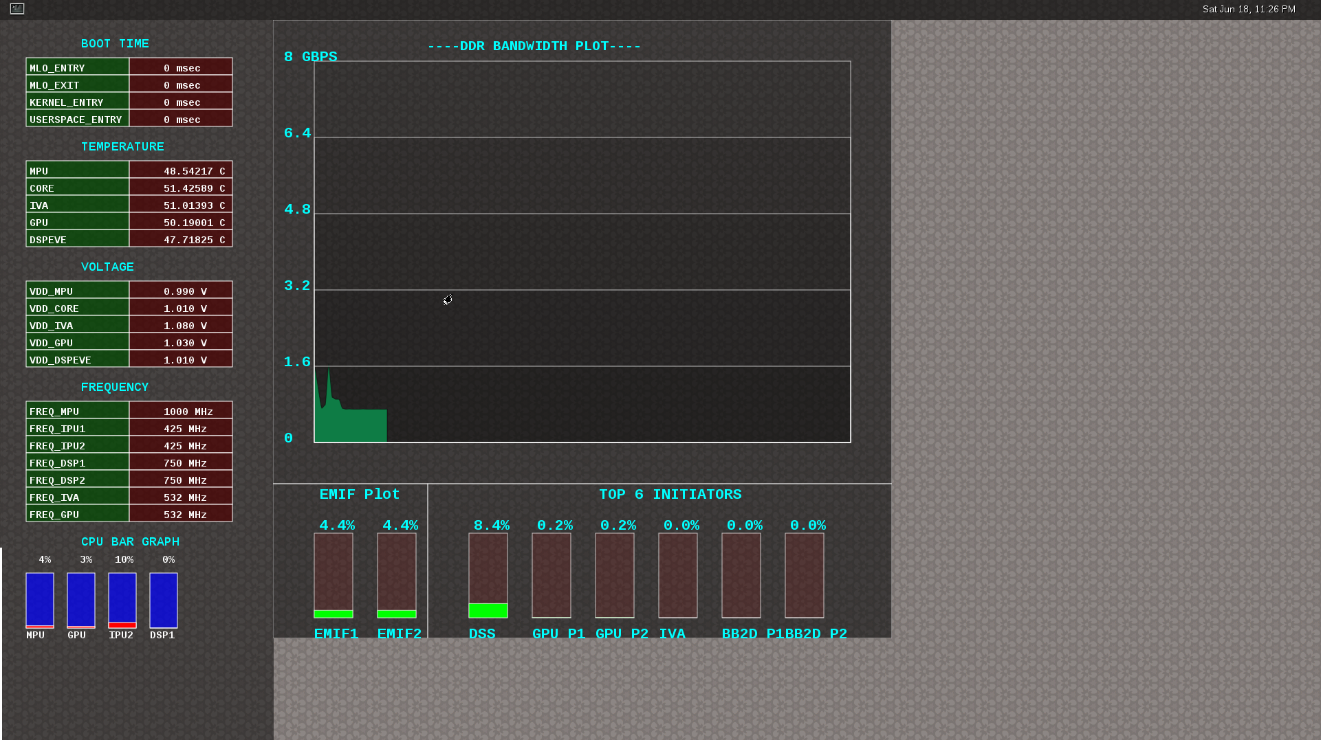
Getting started
- Prepare the card with PLSDK 3.0.0 or later.
- Boot up
- Start weston
target # /etc/init.d/weston start
- Copy the required scripts into a temporary folder (this is to allow you to experiment with the settings later)
target # mkdir temp
target # cd temp
target # cp /etc/glsdkstatcoll/* .
target # cp /etc/visualization_scripts/* .
- You should see the following file in the directory after the above operation.
target # ls -al
drwxr-xr-x 2 root root 4096 Mar 22 18:01 .
drwxr-xr-x 3 root root 4096 Mar 22 18:01 ..
-rw-r--r-- 1 root root 114 Mar 22 18:01 config.ini
-rw-r--r-- 1 root root 265 Mar 22 18:01 dummy_boot_time_results.sh
-rw-r--r-- 1 root root 419 Mar 22 18:01 dummy_cpu_load.sh
-rw-r--r-- 1 root root 899 Mar 22 18:01 getFrequency.sh
-rw-r--r-- 1 root root 2293 Mar 22 18:01 getTemp.sh
-rw-r--r-- 1 root root 371 Mar 22 18:01 getVoltage.sh
-rw-r--r-- 1 root root 254 Mar 22 18:01 initiators.cfg
-rw-r--r-- 1 root root 143 Mar 22 18:01 list-boot-times.sh
-rw-r--r-- 1 root root 367 Mar 22 18:01 send_boot_times_to_monitor.sh
-rw-r--r-- 1 root root 496 Mar 22 18:01 soc_performance_monitor.cfg
-rw-r--r-- 1 root root 133 Mar 22 18:01 start_visualization_test.sh
- Running the soc-performance-monitor, this tool has two pre-requisites.
- The name of the fifo configured in the file soc_performance_monitor.cfg needs to be created
- The file soc_performance_monitor.cfg should be present in the current directory. This should be done in the above steps.
- Creating the fifo (mentioned in the soc_performance_monitor.cfg)
target # mkfifo /tmp/socfifo
- Run the tool for various performance metrics
target # soc-performance-monitor &
- Run the tool for DDR BW Visualization
target # mkfifo /tmp/statcollfifo
target # soc-ddr-bw-visualizer &
The following sections will talk about the how to populate the data into tools and further controls that are possible.
Quick guide to available plugins
Plugins are the entities (scripts/native binaries) that can be used to send commands to the SOC Performance Monitoring tools.
The main intent of this is to separate the visualization engine from the data collection part and allow full configuration of the application.
When the application (soc-performance-monitor) is invoked, it starts up with the default data which is set to zero. To populate the real values, the user can use the scripts provided in the prebuilt filesystem.
Temperature data
The temperature data is read from the on-die temperature registers and sent to the visualization tool. The file system comes with a script that does this functionality.
target # sh getTemp.sh
Invoking the above command will populate the temperature table with the current temperature.
Voltage data
The voltage data is read from the omapconf utility and then parsing out the required information to be later sent to the visualization tool. The file system comes with a script that does this functionality.
target # sh getVoltage.sh
Invoking the above command will populate the Temperature table with the configured voltage for the various rails.
Frequency data
The frequency data is read from the omapconf utility and then parsing out the required information to be later sent to the visualization tool. The file system comes with a script that does this functionality.
target # sh getFrequency.sh
Invoking the above command will populate the Frequency table with the configured frequency for the various cores.
CPU Load information
The CPU load information need individual plugin modules for each of the cores. This is envisioned to be different for different systems. The default filesystem contains the plugins required for reading the MPU(A15) and the GPU(SGX544 MP2). Other plugins for measuring the loads for the IPU1, IPU2, DSP1 and DSP2 will be available at a later time.
Measuring the MPU load
The filesystem is populated with a binary which is called “mpuload” that reads the /proc/stat interface and derives the load. The user can run the utility in the background with the
target # mpuload FIFO
Example usage:
target # mpuload /tmp/socfifo 1000 &
After running this binary the MPU load in the Bar Graph of the CPU load will be updated dynamically at an interval of 1 second.
Measuring the GPU load
The filesystem is populated with a binary called as “pvrscope” that reads the SGX registers via a library called libPVRScopeDeveloper.a This utility invokes the APIs provided by IMG as part of the Imagination PowerVR SDK and then populates the required FIFO.
Usage instructions:
target # pvrscope <option> <time_seconds>
options:
-f write into the FIFO (/tmp/socfifo)
-c output to console
time:
1-n specified in seconds
0 run forever
After running this utility, the GPU load in the BAR Graph of the CPU load area will be updated at an interval of 1 second.
Measuring the DSP load
The filesystem is populated with a binary which is called “dsptop” that collects DSP usage info and then populates the required FIFO.
The user can run the utility in the background with the
target # dsptop –r <update_freq> –f fifo –o /tmp/socfifo –d <update_freq> -n <# of updates>
Example usage:
target # dsptop –r 1 –f fifo –o /tmp/socfifo –d 1 –n 100 &
After running this binary the DSP load in the Bar Graph of the CPU load will be updated at an interval specified by “-r, -d”, for example “-r 1 –d 1” means at an interval of 1 second.
Boot time measurement
This feature will be provided at future release.
Order of execution
The performance visualization tools have to be executed in the following order.
- Launch weston
- Create required FIFOs
- Configure the .cfg file to suit the required settings
- Run the soc-performance-monitor and/or soc-ddr-bw-visualizer
- Run the plugins to populate data
Config file format
The config file has the following format. There are 3 different kinds of sections that can be defined, please refer to the particular section for more details.
The generic format is:
[SECTION_NAME]
VALUE_1
VALUE_2
..
..
VALUE_N
SPECIAL VALUE
<blank line>
Types of sections
- GLOBAL
- TABLE
- BAR GRAPH
GLOBAL section:
The SECTION_NAME is specified as GLOBAL followed by a sequence of key value pairs.
[GLOBAL]
KEY_1=VALUE_1
KEY_2=VALUE_2
..
..
KEY_n=VALUE_n
<blank>
Global configurations
The list of recognized global values are:
- REFRESH_TIME_USECS
- FIFO
- MAX_HEIGHT
- MAX_WIDTH
- X_POS
- Y_POS
REFRESH_TIME_USECS:
- This will dictate the interval at which the utility is going to run.
- The value is specified in micro seconds
- This value decides a major trade-off, lower rate will increase the CPU load and GPU load.
- The ideal value is about 100000 usecs
FIFO:
- The value of this field is the named pipe or fifo that can be used to communicate with the application.
- User would need to create a fifo (application will prompt if it doesn’t exist)
MAX_HEIGHT, MAX_WIDTH:
- The width and height of the application.
- This can be adjusted based on the number of tables and bar graph entities.
X_POS, Y_POS:
- Decide the starting offset of the application.
- Note that there are commands to move the application (Refer commands section).
TABLE section:
The section name can be one of the following:
- BOOT_TIME
- TEMPERATURE
- VOLTAGE
- FREQUENCY
[TABLE_NAME]
VALUE_1
VALUE_2
..
..
VALUE_N
TITLE="TABLE TITLE",UNIT="unit to be displayed"
<blank line>
NOTE: The TITLE=list is a list of comma separated values and TITLE and UNIT are the only supported values.
BAR GRAPH section:
[GRAPH_NAME]
VALUE_1
VALUE_2
..
..
VALUE_N
TITLE OF THE GRAPH
<blank line>
Commands:
The FIFO can be used to communicate with the soc-performance-monitor application and pass data from the command line or from other applications. There are a few commands that have been implemented to aid in modifying the running application via the FIFO.
The commands in general have the following format:
"INSTRUCTION: DATA_1 ... DATA_N"
and they can be sent to the soc-performance-monitor by simply doing an echo:
echo "INSTRUCTION: DATA_1 ... DATA_N" > FIFO
The currently supported list of supported commands are:
- TABLE
- CPULOAD
NOTE: To execute a sequence of commands in a sequence, it is advised that a delay of REFRESH_TIME_USECS be inserted between two commands.
TABLE command
The format of the TABLE command is:
"TABLE: ROW_NAME value unit"
When this command is issued, the tool will find a table entry with the ROW_NAME in Column 0 and then update the Column 1 of the table with “value unit”.
If the ROW_NAME is not found, then this command will have no effect. Please note that this brings in a restriction that all the tables rows will need to have a unique name. In order to ensure this, the soc_performance_monitor.cfg file will have to be reviewed to ensure unique names.
Example: To update the FREQUENCY table for MPU, the user can send the following command:
echo "TABLE: FREQ_MPU 1500 MHz" > /tmp/socfifo
CPULOAD command
The format of the CPULOAD command is:
"CPULOAD: CORE_NAME value" > FIFO
CORE_NAME has to be one of the names specified in the soc_performance_monitor.cfg.
value is in the range 0 to 100
Usually, the CPULOAD command is invoked through an application monitors the load of a specific core.
In each system, the mechanism to retrieve the CPULOAD of a particular core can vary and it is for this reason that several plugins have been provided and serve as an example for further extension.
Example: To update the CPULOAD table for GPU, the user can send the following command:
echo "CPULOAD: GPU 87" > /tmp/socfifo
Executing in debug mode
To launch the application in debug mode for very verbose data on the internal working of the tool, launch the tool with the following option:
# soc-performance-monitor 1
Build instructions
The full source of the tool is available and the required recipes have been updated as part of the recipes and upstreamed to meta-arago.
Essentially, if the user builds the Yocto filesystem as documented in the SDG, the tool will get recompiled as part of it.
Configuration of the soc-ddr-bw-visualizer
Refer to #Using_the_statistics_collector_.28bandwidth_application.29
- The total time that the tool runs is configured using config.ini.
- To allow finer granularity of control to choose the initiators of interest, the user will have to modify the initiators.cfg.
The tool will have to relaunched for the new settings to take effect.
3.8.11. SGX Debug Info
Introduction
The TI OMAP/AM/DM SGX Graphics Driver is closely tied to the environment it is running under, and the configuration it is built with. This article mentions debugging methods specific to Linux.
Baselining the current SGX driver environment
The current SGX driver environment on the target can be observed using the below script.
https://gforge.ti.com/gf/download/docmanfileversion/203/3715/gfx_check.sh
This script performs the below actions:
#!/bin/sh
echo "WSEGL settings"
cat /etc/powervr.ini
echo "------"
echo "ARM CPU information"
cat /proc/cpuinfo
echo "------"
echo "SGX driver information"
cat /proc/pvr/version
echo "------"
echo "Framebuffer settings"
fbset -i
echo "------"
echo "Rotation settings"
cat /sys/class/graphics/fb0/rotate
echo "------"
echo "Kernel Module information"
lsmod
echo "------"
echo "Boot settings"
cat /proc/cmdline
echo "------"
echo "Linux Kernel version"
uname -a
Run-time checks/configuration of the SGX driver
One can confirm whether the SGX drivers have been properly installed by checking the following
- One should have seen the message on serial console- “Initializing the graphics driver ...” just before getting the linux command prompt.
- lsmod shows pvrsrvkm module inserted successfully without any error messages on console.
The SGX driver can be configured at run-time on the target using a configuration file.
The optional configuration file is installed by the Processor SDK installer at,
/etc/powervr.ini
Configuration items are specified using the below syntax
KeyWord=ParamValue
Important configuration parameters are mentioned below.
WindowSystem
* WindowSystem - This configuration item controls the low level window system that the EGL implementation should hook it up. This item takes the below values
* libpvrDRMWSEGL.so (DRM-based WS for VSync synchronised writes to Framebuffer - slower, but avoids tearing)
* libpvrGBMWSEGL.so (GBM-based WS where it is up to application to perform KMS operations)
DisableHWTextureUpload
* DisableHWTextureUpload - This configuration item enables/disables the use of SGX Transfer queue hardware.
* If set to 1, uses software upload (copying from driver to SGX) of textures, rather than transfer queue (using the SGX hardware).
* Useful to rule out problems in TQ.
DefaultPixelFormat
* DefaultPixelFormat - This configuration item sets the default display pixel format.
- For eg if one wants to configure the default pixel format, then edit /etc/powervr.ini to have following line
- DefaultPixelFormat=ARGB8888
- For AM3 Beagle Bone Black EVM
- DefaultPixelFormat=RGB565
SGX Driver Failure Modes (Installation)
Unable to install the kernel modules (pvrsrvkm.ko)
1. The Linux kernel has to be built with “modules” support (make ti-sgx-ddk-km and make ti-sgx-ddk-km_install)
2. The kernel modules of the Graphics driver have to be built, after the linux kernel is built in the above manner. ie, the kernel modules need to match the kernel version that will actually run on the target.
3. If the services kernel module (pvrsrvkm.ko) does not load, it is likely because of mismatches between user mode binaries and kernel modules. If the kernel modules are built correctly as specified, post the issue on the E2E forum with the output of the gfx_check.sh script linked in earlier section.
SGX Driver Failure Modes (Run time)
Vertical Tearing/ Artifacts/ Clipping issues/ Missing objects
This could potentially be due to an incorrect usage in the OpenGL application, or point to an issue in the driver. Note that the deferred rendering mode of the SGX HW, will cause different behaviour compared to the immediate renderers found on desktops.
Please contact TI through the Linux E2E forums (https://e2e.ti.com/)
Demos are not running at required speed, How to check SGX clock rate?
If the demos are running slower than expected, check and ensure that the clock frequency set for the SGX driver is correct. This can be done by the following code in the KM kernel drivers -
File - eurasia_km/services4/system/omap/sysutils_linux.c Function - EnableSGXClocks()
You can print the SGX clock rate in debug build as below -
IMG_UINT32 rate = clk_get_rate(psSysSpecData->psSGX_FCK);
PVR_TRACE(("Sgx clock is %dMHz", HZ_TO_MHZ(rate)));
Depending on the TI platform used, this will vary from 200 to 532 MHz. Ensure that SGX is running at the right clock.
If this is right & still demos are not running with expected performance, it is needed to optimize the application, and its usage of OpenGL API.
Qt demos do not work when powerVR is enabled
1. Confirm that the GLES2 demos provided in the Graphics SDK are running properly with default SDK configuration of the window system.
- Confirm that kernel module (pvrsrvkm.ko) is successfully loaded.
3. Confirm with fbset command to check alpha to be non zero. If not set to appropriate value using fbset. QT supports 16, 32 bpp but expects alpha to be non zero for 32 bpp.
4. If above steps are correct, post to E2E forum with the output of the gfx_check.sh script linked in earlier section. Also attach the console log, with the below option enabled in the environment
"QT_DEBUG_PLUGINS=1"
Posting to E2E forum
For suggestions or recommendations or bug reports, post details of your application as below to the E2E forums (https://e2e.ti.com/), with below information:
- Output of gfx environment baseline script available below, run on the target:
https://gforge.ti.com/gf/download/docmanfileversion/203/3715/gfx_check.sh
- Details of UI application, as shown in below sheet.
https://gforge.ti.com/gf/download/docmanfileversion/220/3798/UI_graphics_reqs_sheet_v1.xls
These two outputs will help in debugging common issues.
3.9. Multimedia
Introduction
TI’s embedded processors such as AM57xx have following hardware accelerators.
- IVA (Image and Video Accelerator) for accelerating multimedia encode and decode.
- VPE (Video Processing Engine) for Scaling, Color Space Conversion and Deinterlacing.
- C66x DSP cores for offloading certain image/video and/or voice/audio processing.
In order to make it easy for customers to write applications, and to leverage open source elements that provide functionality such as AVI stream demuxing, audio encode/decode, etc, TI’s PROCESSOR-SDK supplies ARM based GStreamer plugins that abstracts the hardware accelerator offload.
This multimedia training page will cover the following topics.
- Capabilities of IVA-HD, VPE, DSP, and ARM
- Out of Box Multimedia Demos in PROCESSOR-SDK
- Software Stack of Accerelated Codec Encoding/Decoding
- Gstreamer Pipelines for Multimedia Applications
- DSP C66x Gstreamer Plugin Internals
- Rebuild IPUMM Firmware
- Load and Unload Firmware
Capabilities of IVA-HD, VPE, DSP, and ARM
In PROCESSOR-SDK, IVA-HD, and hence the multimedia encoding and decoding applications, supports the following codecs.
- Video Decode: H264, MPEG4, MPEG2, and VC1
- Video Encode: H264, and MPEG4
- Image Decode: MJPEG
Codec datasheet can be downloaded from git repository here - https://git.ti.com/ivimm/ipumm/trees/master/extrel/ti/ivahd_codecs/packages/ti/sdo/codecs
VPE supports video operations such as scaling, color space conversion, and de-interlacing.
- Supported Input formats: NV12, YUYV, UYVY
- Supported Output formats: NV12, YUYV, UYVY, RGB24, BGR24, ARGB24, ABGR24
DSP is a general purpose programmable core available for offloading signal processing kernels.
- Sample Image Processing Kernels integrated in the DSP gstreamer plugin: Median2x2, Median3x3, Sobel3x3, Conv5x5, Canny
Demo applications also demonstrate the following ARM based coding capabilities.
- Video decoding on ARM: H.265
- Audio encoding and decoding on ARM: AAC, MPEG2 (leveraging open source codecs)
Multimedia Demos Available via Matrix
The following Multimedia demos are available via Matrix on AM57xx EVM (X15 board with LCD). The table below provides a list of these demos, with a brief description.
| Demo Name | Details |
| IVAHD H264 Decode | This demo runs a gstreamer playbin pipeline to decode H264 using IVAHD. The demo plays back audio as well and you can listen if speakers are connected. |
| IVAHD H264 Encode | This demo runs a gstreamer pipeline to do H264 encoding on IVAHD. The input clip is in NV12 format. The output is saved to /home/root directory |
| AAC Decode | This demo runs a gstreamer playbin pipeline for ARM audio decoding and playout. |
| H.265 (HEVC) Decode | This demonstrates HEVC decoding on ARM. The gstreamer pipeline decodes and display an H265 stream. |
| VIP VPE IVAHD MPEG4 Encode and Decode | This demonstrates video capture via Video Input Port (VIP), color space conversion and scaling with Video Processing Engine (VPE), IVAHD MPEG4 encoding, IVAHD MPEG4 decoding and display |
| DSP C66 Image Processing | This demonstrates the use of DSP C66x plugin (dsp66videokernel) for offloading image processing tasks to DSP. |
Software Stack of Accelerated Codec Encoding/Decoding
As shown in the figure below, the software stack of the accelerated codec encoding/decoding runs on two subsystems: MPU subsystem on ARM-A15, and IPU subsystem on ARM-M4. The two subsystems communicate with each other through RPMSG. At the highest level in MPU subsystem on ARM-A15, there is Linux user space application which is based on Gstreamer. GStreamer is an open source framework that simplifies the development of multimedia applications. The GStreamer library loads and interfaces with the TI GStreamer plugin (GST-Ducati plugin), which handles all the details specific to use of the hardware accelerator. Specifically, TI GStreamer plugin interfaces libdce in user space. On one hand, libdec interacts with libdrm in user space for displaying video in Wayland window system. On the other hand, libdce interfaces with RPMSG in Linux kernel to communicate with the IPU subsystem on ARM-M4. The IPU subsystem builds on SYS/BIOS RTOS and runs IVAHD video/image codecs, utilizing framework components and codec engine.
Overview of the Multimedia Software Stack
The Multimedia software contains many software components. Some are developed by Texas Instruments and some are developed in and by the open source community(White). TI contributes, and sometimes even maintains, some of these open source community projects, but the support model is different from a project developed solely by TI.
Gstreamer Pipelines for Multimedia
Open Source GStreamer Overview
GStreamer is an open source framework that simplifies the development of multimedia applications, such as media players and capture encoders. It encapsulates existing multimedia software components, such as codecs, filters, and platform-specific I/O operations, by using a standard interface and providing a uniform framework across applications.
The modular nature of GStreamer facilitates the addition of new functionality, transparent inclusion of component advancements and allows for flexibility in application development and testing. Processing nodes are implemented via Gstreamer plugins with several sink and/or source pads. Many plugins are running as ARM software implementation, but for more complex SoCs certain functions are better executed on hardware accelerated IPs like IVAHD (video codecs) or VPE.
Gstreamer is multimedia framework based on data flow paradigm. It allows easy plugin registration just by deploying new shared objects to /usr/lib/gstreamer-1.0 folder. The shared libraries in this folder are scanned for reserved data structures identifying capabilities of individual plugins. Individual processing nodes can be interconnected as a pipeline in run-time creating complex topologies. Node interfacing compatibility is verified at that time - before pipeline is started.
GStreamer brings a lot of value-added features to Processor SDK, including audio encoding and decoding, audio and video synchronization, interaction with a wide variety of open source plugins (muxers, demuxers, codecs, and filters). New GStreamer features are continuously being added, and the core libraries are actively supported by participants in the GStreamer community. Additional information about the GStreamer framework is available on the GStreamer project site: https://gstreamer.freedesktop.org/.
TI Provided Gstreamer Plugins
One benefit of using GStreamer as a multimedia framework is that the core libraries already build and run on ARM Linux. Only a GStreamer plugin is required to enable additional hardware features on TI’s embedded processors with both ARM and hardware accelerators for multimedia. The TI GStreamer plugins provide elements for GStreamer pipelines that enable the use of plug-and-play IVAHD codecs, certain hardware-accelerated operations such as video frame resizing, de-interlacing, and color space conversion, image processing offloaded to DSP, and ARM based HEVC decoding. The TI GStreamer plugins provide baseline support for eXpressDSPTM Digital Media (xDM1) plug-and-play codecs. Multiple xDM versions are supported, making it easy to migrate between codecs that conform to different versions of the xDM specification.
Below is a list of TI GStreamer plugins provided in Processor SDK.
- Ducati Decoding and Encoding
- ducatih264dec
- ducatimpeg4dec
- ducatimpeg2dec
- ducativc1dec
- ducatijpegdec
- ducatih264enc
- ducatimpeg4enc
- Ducati VPE
- vpe
- ducatih264decvpe
- ducatimpeg2decvpe
- ducatimpeg4decvpe
- ducatijpegdecvpe
- ducativc1decvpe
- DSP Image Processing
- dsp66videokernel
- ARM HEVC Decoding
- h265dec
Visual Representation of Typical GStreamer Pipelines
A typical GStreamer pipeline starts with one or more source elements, uses zero or more filter elements, and ends in a sink or multiple sinks. This section provides visual representation of two typical gstreamer pipelines: 1) multimedia decoding and playout, and 2) video capture, encoding, and network transmission.
Decode Pipeline
The example pipeline shown in the figure below demonstrates the demuxing and playback of a transport stream. The input is first read using the source element, and then processed by gstreamer playbin2. Inside playbin2, demuxer first demuxes the stream into its audio and video stream components. The video stream is then queued and sent to TI ducati gstreamer plugin for decoding. Finally, it is sent to a video sink to display the decoded video on the screen. The audio stream is queued and then decoded by ARM audio gstreamer plugin, and then reaches its destination at the alsasink element to play the decoded audio.
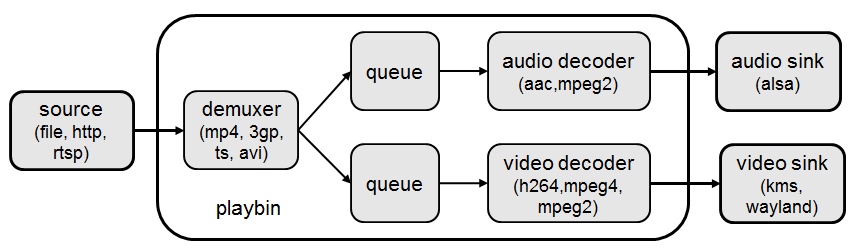
Encode Pipeline
The example pipeline shown in the figure below demonstrates video capture, encode, muxing, and network transmission. The camera capture is processed by VPE, and then queued for video encoding. After that, it is queued for video parsing, muxing. Finally, it is sent to network through RTP payloader and udp sink.

Gstreamer test pipeline:
–need someone to add this code to make it work. only showing a figure.
Running a gstreamer pipeline
Gstreamer pipelines can also run from command line. In order to do so, exit Weston by pressing Ctrl-Alt-Backspace from the keyboard which connects to the EVM. Then, if the LCD screen stays in “Please wait...”, press Ctrl-Alt-F1 to go to the command line on LCD console. After that, the command line can be used from serial console, SSH console, or LCD console.
One can run an audio video file using the gstreamer playbin from the console. Currently, the supported Audio/video sink is kmssink, waylandsink and alsassink.
kmssink:
target # gst-launch-1.0 playbin uri=file:///<path_to_file> video-sink=kmssink audio-sink=alsasink
waylandsink:
1. refer Wayland/Weston to start the weston
2. target # gst-launch-1.0 playbin uri=file:///<path_to_file> video-sink=waylandsink audio-sink=alsasink
The following pipelines show how to use vpe for scaling and color space conversion.
1. Decode-> Scale->Display
target # gst-launch-1.0 -v filesrc location=example_h264.mp4 ! qtdemux ! h264parse ! \
ducatih264dec ! vpe ! 'video/x-raw, format=(string)NV12, width=(int)720, height=(int)480' ! kmssink
2. Color space conversion:
target # gst-launch-1.0 -v videotestsrc ! 'video/x-raw, format=(string)YUY2, width= \
(int)1280, height=(int)720' ! vpe ! 'video/x-raw, format=(string)NV12, width=(int)720, height=(int)480' \
! kmssink
Note
- While using playbin for playing the stream, vpe plugin is automatically picked up. However vpe cannot be used with playbin for scaling. For utilizing scaling capabilities of vpe, using manual pipeline given above is recommended.
- Waylandsink and Kmssink uses the cropping metadata set on buffers and does not require vpe plugin for cropping
The following pipelines show how to use v4l2src and ducatimpeg4enc elements to capture video from VIP and encode captured video respectively.
Capture and Display Fullscreen
target # gst-launch-1.0 v4l2src device=/dev/video1 num-buffers=1000 io-mode=4 ! 'video/x-raw, \
format=(string)YUY2, width=(int)1280, height=(int)720' ! vpe num-input-buffers=8 ! queue ! kmssink
Note:
The following pipelines can also be used for NV12 capture-display usecase.
Dmabuf is allocated by v4l2src if io-mode=4 and by kmssink and imported by v4l2src if io-mode=5
target # gst-launch-1.0 v4l2src device=/dev/video1 num-buffers=1000 io-mode=4 ! 'video/x-raw, \
format=(string)NV12, width=(int)1280, height=(int)720' ! kmssink
target # gst-launch-1.0 v4l2src device=/dev/video1 num-buffers=1000 io-mode=5 ! 'video/x-raw, \
format=(string)NV12, width=(int)1280, height=(int)720' ! kmssink
Capture and Display to a window in wayland
1. refer Wayland/Weston to start the weston
2. target # gst-launch-1.0 v4l2src device=/dev/video1 num-buffers=1000 io-mode=4 ! 'video/x-raw, \
format=(string)YUY2, width=(int)1280, height=(int)720' ! vpe num-input-buffers=8 ! queue ! waylandsink
Note:
The following pipelines can also be used for NV12 capture-display usecase. Dmabuf is allocated by v4l2src
if io-mode=4 and by waylandsink and imported by v4l2src if io-mode=5.
Waylandsink supports both shm and drm. A new property use-drm is added to specify drm allocator based bufferpool to be used.
When using ducati or vpe plugins, use-drm is set in caps as true.
target # gst-launch-1.0 v4l2src device=/dev/video1 num-buffers=1000 io-mode=4 ! 'video/x-raw, \
format=(string)NV12, width=(int)1280, height=(int)720' ! waylandsink use-drm=true
target # gst-launch-1.0 v4l2src device=/dev/video1 num-buffers=1000 io-mode=5 ! 'video/x-raw, \
format=(string)NV12, width=(int)1280, height=(int)720' ! waylandsink use-drm=true
Capture and Encode into a MP4 file.
target # gst-launch-1.0 -e v4l2src device=/dev/video1 num-buffers=1000 io-mode=4 ! 'video/x-raw, \
format=(string)YUY2, width=(int)1280, height=(int)720, framerate=(fraction)30/1' ! vpe num-input-buffers=8 ! \
queue ! ducatimpeg4enc bitrate=4000 ! queue ! mpeg4videoparse ! qtmux ! filesink location=x.mp4
Note:
The following pipeline can be used in usecases where vpe processing is not required.
target # gst-launch-1.0 -e v4l2src device=/dev/video1 num-buffers=1000 io-mode=5 ! 'video/x-raw, \
format=(string)NV12, width=(int)1280, height=(int)720, framerate=(fraction)30/1' ! ducatimpeg4enc bitrate=4000 ! \
queue ! mpeg4videoparse ! qtmux ! filesink location=x.mp4
Capture and Encode and Display in parallel.
target # gst-launch-1.0 -e v4l2src device=/dev/video1 num-buffers=1000 io-mode=4 ! 'video/x-raw, \
format=(string)YUY2, width=(int)1280, height=(int)720, framerate=(fraction)30/1' ! vpe num-input-buffers=8 ! tee name=t ! \
queue ! ducatimpeg4enc bitrate=4000 ! queue ! mpeg4videoparse ! qtmux ! filesink location=x.mp4 t. ! queue ! kmssink
Below provides more gstreamer pipeline examples.
File to file video encoding pipeline:
target # gst-launch-1.0 filesrc location=waterfall-352-288-nv12-inp.yuv ! videoparse width=352 height=288 format=nv12 ! video/x-raw, width=352, height=288 ! ducatih264enc ! filesink location=waterfall-352-288-nv12-inp_gst.h264
The cap filter of “video/x-raw, width=352, height=288” is needed in this pipeline to specify the width and height. Otherwise, variable width and height are configured for the encoder and the encoded output can be corrupted.
File to file 4K H264 encoding pipeline
target # gst-launch-1.0 filesrc location= 4k.nv12 ! videoparse width=3840 height=2160 format=nv12 framerate=12/1 ! video/x-raw, width=3840, height=2160 ! ducatih264enc level=51 profile=100 bitrate=16000 ! filesink location=4k.h264
ARM H265 (HEVC) decoding pipeline
target # gst-launch-1.0 filesrc location=<file>.265 ! 'video/x-raw, format=(string)NV12, framerate=(fraction)24/1, width=(int)1280, height=(int)720' ! h265dec threads=2 ! vpe ! kmssink
DSP offloaded image processing pipeline
target # gst-launch-1.0 filesrc location=<file>.265 ! 'video/x-raw, format=(string)NV12, framerate=(fraction)24/1, width=(int)1280, height=(int)720' ! h265dec threads=1 ! videoconvert ! dsp66videokernel kerneltype=1 filtersize=9 lum-only=1 ! videoconvert ! vpe ! 'video/x-raw, format=(string)NV12, width=(int)640, height=(int)480' ! kmssink
This pipeline decodes an H265 clip on ARM A15, offloads the image processing task (Sobel 3x3 kernel) to DSP, and the processed clip is then re-sized and displayed.
Processor SDK provides reference implementation of multiple image processing kernels, for which the pipeline can be configured as shown in the table below.
| Kernel Type | Definition in GST Pipeline |
| Median2x2 | dsp66videokernel kerneltype=0 filtersize=5 lum-only=0 |
| Median3x3 with luminance only | dsp66videokernel kerneltype=0 filtersize=9 lum-only=1 |
| Sobel3x3 with luminance only | dsp66videokernel kerneltype=1 filtersize=9 lum-only=1 |
| Conv5x5 | dsp66videokernel kerneltype=2 filtersize=25 lum-only=0 |
| User defined kernel with Sobel3x3 and luminance only | dsp66videokernel kerneltype=4 arbkernel=Sobel3x3 filtersize=9 lum-only=1 |
- Audio/Video decoding with http input source
target # gst-launch-1.0 playbin uri=http://<link_to_file> video-sink=kmssink audio-sink=alsasink
- Audio/Video decoding with rtsp input source First, set up and run RTSP server on host. Then, run the following command:
target # gst-launch-1.0 playbin uri=rtsp://<link_to_file> video-sink=kmssink audio-sink=alsasink
- Record real-time FPS of video decoding
target # gst-launch-1.0 -v playbin uri=file:///<path_to_file> video-sink=fpsdisplaysink audio-sink=alsasink > fps_log.txt
Note: please view fps_log.txt to find out the FPS information after the pipeline completes.
DSP C66x Gstreamer Plugin Internals
TI’s Processor SDK Linux supplies ARM based GStreamer plugin that abstracts C66x DSP offload. The primary goal of this DSP GStreamer plugin is to demonstrate how C66x can be used in GStreamer framework, in combination with other GStreamer plugins. The plugin, under the hood, uses OpenCL to dispatch to the C66x cores. This plugin provides sample DSP kernels and can be used as a reference to develop user’s own DSP kernels.
Overview of Existing Source Code
Source code of the DSP plugin can be found from https://git.ti.com/processor-sdk/gst-plugin-dsp66.
As shown in the figure below, the GST plugin code (gstdsp66*.c and gstdsp66*.h files) is directly under the ./src folder. It is implemented in C following GST framework requirements, and therefore it is compatible with the gstreamer version used in Processor-SDK-Linux.
Dispatch of work load to DSP is done via call to functions in independent shared objects, which are implemented in OpenCL code organized under the kernels folder. The kernels folder currently has a sub-folder of oclconv, which provides sample DSP kernels for image processing. As long as the APIs between the GST plugin code (in ./src folder) and OpenCL code (in ./src/kernels/oclconv folder) are the same, this shared object can be compiled and installed separately. This approach allows easier modification, implementation and maintenance once the APIs are fixed.
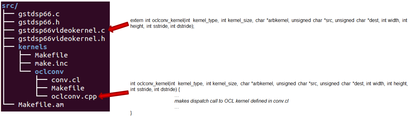
The image processing functions in oclconv are implemented via calls to DSP optimized imglib and vlib library functions, or implemented in OpenCL C.
- Kernels implemented with OpenCL C: Median2x2
- Kernels implemented with imglib function calls from OpenCL C: Median3x3, Sobel3x3, Conv5x5
- Kernels implemented with vlib function calls from OpenCL C: Canny
Adding Custom DSP Kernels
Using the existing oclconv as the template, more folders can be added under ./src/kernels folder to create shared libraries with additional wrappers (for functions invoked from GST plugin context) and OCL (host side and DSP) kernels. Makefile in ./src/kernels folder will attempt make in all sub-folders. Each sub-folder will provide independent shared library object that can be invoked from gstdsp66 context (e.g., function calls in ./src/gstdsp66videokernel.c file). Individual shared object libraries can be independently recompiled and updated in the target file system.
Modifying the Existing Plugin
The DSP plugin also allows easy modifications and additions, and below are some examples.
Currently the DSP plugin provides five sample image process operations: 1) Median2x2; 2) Median3x3; 3) Sobel3x3; 4) Conv5x5; and 5) Canny. Users can modify the source code to add more image processing operations as needed.
Currently the DSP plugin provides properties as below. More properties can be added so that they can be passed from gst-launcher.
- kerneltype: select the kernel type
- filtersize: the size of the filter, choose from (5,9,25)
- lum-only: true for applying the filter on luminance only, false for applying on all three planes.
- arbkernel: provide a way to specify the name of the kernel invoked via OpenCL.
Details of a specific image processing kernel can also be modified, e.g., the coefficients for Conv5x5 kernel, which are defined in kernels/oclconv/conv.cl::kernel void Conv5x5() function.
Rebuilding and Installing the Plugin
After modifications/additions are made for the DSP plugin source code, the plugin needs to be rebuilt, and this can be done from the Yocto build.
First, please refer to Processor SDK Building The SDK to set up the build environment and bitbake the original recipe for gstreamer1.0-plugins-dsp66, i.e.,
MACHINE=am57xx-evm bitbake gstreamer1.0-plugins-dsp66
After the bitbake command above is successfully done, ./build/arago-tmp-external-linaro-toolchain/work/cortexa15hf-vfp-neon-linux-gnueabi/gstreamer1.0-plugins-dsp66/git-r<*> will be created with the original source code under the git sub-folder. Copy the modified and/or the newly added files to the git sub-folder, and rebuild the plugin referring to Rebuild Recipe.
Last, install the rebuilt plugin on target filesystem referring to Install Package. After the installation, the following files will be updated and/or added. Gstreamer framework includes seamless detection and registration of the new plugin.
- /usr/lib/gstreamer-1.0/libgstdsp66.so
- /usr/lib/liboclconv.so
- [optional] any additional shared library (as described in previous section), should be placed in /usr/lib
Rebuild IPUMM Firmware
Pre-built IPUMM firmware images can be located on target file system at /lib/firmware/dra7-ipu2-fw.xem4. In case there is a need to rebuild the IPUMM firmware, the instructions below are provided for rebuilding IPUMM firmware. It assumes that everything is done on a Ubuntu machine.
IPUMM GIT Repo
IPUMM is publically available at https://git.ti.com/ivimm/ipumm. To clone the git repository, execute the following command.
git clone git://git.ti.com/ivimm/ipumm.git
To checkout a particular tag, e.g., 3.00.09.01, run the following command:
cd ipumm
git checkout [tag, e.g., 3.00.09.01]
IPUMM Build Tools
Making IPUMM depends on the following tools.
- Codec Engine: Codec Engine Product Releases
- Framework Components: Framework Components Product Releases
- IPC: IPC Product Releases
- XDAIS: XDAIS Product Releases
- BIOS: SYS/BIOS Product Releases
- XDC Tools: XDCTools Product Releases
- TMS470 CGT ARM: The compiler tools are provided as part of CCS.CCSv6 Download
Each release of IPUMM is verified with particular versions of the tools above. Check top level Makefile of ipumm to identify the versions to be downloaded and installed. For example, the tool versions used in IPUMM 3.00.09.01 are listed as below:
XDCVERSION ?= xdctools_3_31_02_38_core
BIOSVERSION ?= bios_6_42_02_29
IPCVERSION ?= ipc_3_40_01_08
CEVERSION ?= codec_engine_3_24_00_08
FCVERSION ?= framework_components_3_40_01_04
XDAISVERSION ?= xdais_7_24_00_04
# TI Compiler Settings
export TMS470CGTOOLPATH ?= $(BIOSTOOLSROOT)/ccsv6/tools/compiler/ti-cgt-arm_5.2.5
Below are direct download links and install instructions for IPUMM 3.00.09.01 build tools. When installing the tools, it is preferable to install all the tools to the same directory, e.g., /opt/ti.
- Download and untar codec_engine_3_24_00_08,lite.tar.gz
- Download and untar framework_components_3_40_01_04,lite.tar.gz
- Download and unzip ipc_3_40_01_08.zip
- Download and untar xdais_7_24_00_04.tar.gz
- Download and install bios_setuplinux_6_42_02_29.bin
- Download and untar xdctools_3_31_02_38_core_linux.zip
- Download and install CCSv6 Build#6.1.1.00022. Ensure that “TI ARM Compiler” is selected during the installation. After the installation, the compiler tools (version 5.2.5) are located at [ccs_install_dir]/ccsv6/tools/compiler/ti-cgt-arm_5.2.5.
Build IPUMM
Setup Environment
Export the following environment variables:
export BIOSTOOLSROOT=<path where all tools are hosted>
export IPCSRC=<path where IPC is installed>
export TMS470CGTOOLPATH=<path to CGTOOL ARM Compiler is installed>
Example for IPUMM 3.00.09.01 assuming all the tools are installed to /opt/ti directory:
export BIOSTOOLSROOT=/opt/ti
export IPCSRC=/opt/ti/ipc_3_40_01_08
export TMS470CGTOOLPATH=/opt/ti/ccsv6/tools/compiler/ti-cgt-arm_5.2.5
Build IPUMM
Follow the steps below to build IPUMM firmware.
export HWVERSION=ES10
cd ipumm
make unconfig
make vayu_smp_config
make clean
make ducatibin
After the build is completed, two different images will get created. Select the correct one for your devices.
* dra7-ipu2-fw.xem4: This firmware will be used for Linux or Android.
The firmware is built with the resource table defined in platform/ti/dce/baseimage/custom_rsc_table_vayu_ipu.h
The corresponding map file is: platform/ti/dce/baseimage/package/cfg/out/ipu/release/ipu.xem4.map
* dra7xx-m4-ipu2.xem4: This firmware will be used for QNX.
The firmware is built with the resource table defined in platform/ti/dce/baseimage/qnx_custom_rsc_table_vayu_ipu.h
The corresponding map file is: platform/ti/dce/baseimage/package/cfg/out/ipu/release/qnx_ipu.xem4.map
Firmware Loading and Unloading
The table below shows the remote cores and their corresponding definitions in the kernel dtsi files ([ti-processor-sdk-linux-am57xx-evm-[ver]]/board-support/linux-[ver]/arch/arm/boot/dts/dra7.dtsi, and dra74x.dtsi), as well as the argument to be used in the loading/unloading commands.
| Remote Core | Definition in dtsi file | Argument in loading/unloading |
| IPU1 | ipu@58820000 | 58820000.ipu |
| IPU2 | ipu@55020000 | 55020000.ipu |
| DSP1 | dsp@40800000 | 40800000.dsp |
| DSP2 | dsp@41000000 | 41000000.dsp |
For example, the argument of 55020000.ipu corresponds to IPU2 as can be seen from dra7.dtsi.
ipu2: ipu@55020000 {
compatible = "ti,dra7-rproc-ipu";
In the sections below, 55020000.ipu will be used as the example. For a specific use case, please select the corresponding argument which is applicable.
Unloading and loading remotecores at runtime
It is possible to unload and reload a remotecore at runtime from Linux using the sysfs interface.
target $ cd /sys/bus/platform/drivers/omap-rproc/
target $ echo 55020000.ipu > unbind
target $ echo 55020000.ipu > bind
The echo 55020000.ipu > unbind command tears down the communication channels between the A15 and the remotecore and unloads the remotecore. Any application level shutdown that needs to be performed needs to be handled by the system integrator.
The echo 55020000.ipu > bind loads the appropriate firmware binary onto the remotecore.
Changing the remotecore binary at runtime
To change the remotecore binary at runtime
- Unload the remotecore using unbind.
- Change the remotecore binary in the firmware folder. Default location is /lib/firmware on the target filesystem.
- Load the remotecore using bind.
target $ cd /sys/bus/platform/drivers/omap-rproc/
target $ echo 55020000.ipu > unbind
target $ cp /home/root/new-binary.xem4 /lib/firmware/dra7-ipu2-fw.xem4
target $ echo 55020000.ipu > bind
If it is desirable to avoid overwriting the existing remote binaries, the method of symbolic links can be used instead of direct copy. For example, Processor SDK provides two types of DSP remotecore binaries: one for DSPDCE (dra7-dsp1-fw.xe66.dspdce-fw) and another one for OpenCL (dra7-dsp1-fw.xe66.opencl-monitor). dra7-dsp1-fw.xe66 is created as a symbolic link by default pointing to the OpenCL binary. When it is needed to switch to DSPDCE, the symbolic link of dra7-dsp1-fw.xe66 can be updated pointing to dra7-dsp1-fw.xe66.dspdce-fw.
target $ cd /sys/bus/platform/drivers/omap-rproc/
target $ echo 40800000.dsp > unbind
target $ rm /lib/firmware/dra7-dsp1-fw.xe66
target $ ln -s /lib/firmware/dra7-dsp1-fw.xe66.dspdce-fw /lib/firmware/dra7-dsp1-fw.xe66
target $ echo 40800000.dsp > bind
After the switch, copycodectest application can be run to verify that DSPDCE firmware is loaded. This application fills the input buffer with a number entered as the argument and after process the output buffer is tested for the same pattern.
usage: copycodectest pattern.
Example:
target # copycodectest 123
Sample console output:
root@am57xx-evm:~# copycodectest 123
0x22070: Opening Engine..
Created dsp_universalCopy
Fill input buffer with pattern 123
Verifing the UniversalCopy algorithm
copycodectest executed successfully
Loading firmware during initial boot without using udev
During the default boot, firmware is supplied to the kernel by udev. Starting the udev service on boot causes a few seconds increase in boot time. In cases where a quick boot is required, the user may not start the udev service in boot. In such cases, firmware can be supplied to the kernel using the sysfs interface. An example script is shown below.
FW_NAMES="dra7-dsp1-fw.xe66 dra7-dsp2-fw.xe66 dra7-ipu1-fw.xem4 dra7-ipu2-fw.xem4"
for FW in $FW_NAMES ; do
echo 1 > /sys/class/firmware/$FW/loading
cat /lib/firmware/$FW > /sys/class/firmware/$FW/data
echo 0 > /sys/class/firmware/$FW/loading
done
3.11. OpenCV
Introduction
OpenCV (Open Source Computer Vision Library) is an open-source BSD-licensed library that includes several hundreds of computer vision algorithms. It is designed for computational efficiency with strong focus on real-time application.
The OpenCV 3.1 release provides a transparent API that allows seamless offloads of OpenCL kernels when a supported accelerator is available. Documentation, tutorials and examples of how to use OpenCV 3.1 are available here.
This document outlines the specifics of how to test OpenCV that has been released within Processor SDK. This release is based off OpenCV 3.1.
OpenCV implementation is available for the following TI devices:
- AM335X
- AM437X
- AM57X/DRA7xx
- K2E
- K2H
- K2L
- K2G
To meet the requirements of real-time processing of images and video OpenCV functions were optimized.
More-ever, TI’s OpenCV implementation of hybrid ARM-DSP devices (AM57X, K2E, K2H, K2L, K2G) provides very efficient implementation of OpenCV function where signal-processing-rich algorithms are processed by DSP while the ARM processes all other algorithms, controls and manages the DSP.
TI implementation of OpenCV contains implementation of OpenCV functions as well as a set of unit tests to verify the performances and the accuracy of the implementation.
This document provides instructions show how to load and run unit tests of TI’s OpenCV implementation.
OpenCV Modules Supported By TI
Table 1 lists the modules of OpenCV and indicates which modules are supported by Processor SDK for K2H family and AM57X family.
| Module Name | K2 Family Support | AM57x Family Support | Comments |
|---|---|---|---|
| calib3d | Yes | Yes | |
| Core | Yes | Yes | |
| features2d | Yes | Yes | |
| flann | Yes | Yes | |
| imgcodecs | Yes | Yes | |
| imgproc | Yes | Yes | |
| ml | Yes | Yes | |
| objdetect | Yes | Yes | |
| photo | Yes | Yes | |
| shape | Yes | Yes | |
| stiching | Yes | Yes | |
| superres | Yes | Yes | |
| video | Yes | Yes | |
| videoio | Yes | Yes | |
| cudaarithm | No | No | No cuda support |
| cudabgsegm | No | No | No cuda support |
| cudacodec | No | No | No cuda support |
| cudafeatures2d | No | No | No cuda support |
| cudafilters | No | No | No cuda support |
| cudaimgproc | No | No | No cuda support |
| cudalegacy | No | No | No cuda support |
| cudaobjdetect | No | No | No cuda support |
OpenCL offload
OpenCV 3.1 provides a transparent API that allows seamless offloads of OpenCL kernels when a supported hardware accelerator is available. OpenCV 3.1 available with Processor SDK allows these OpenCL kernels to be offloaded to the C66x DSP.
OpenCV 3.1 supports approximately 200+ OpenCL kernels that optimize key functionalities in the different modules. The OpenCL kernel offload through the transparent API is enabled by the UMat data structure that replaces the legacy Mat data structure. UMat uses the OpenCL memory allocation procedure whenever possible, but maintains backward compatibility with Mat data structure. Additional explanation can be found on OpenCV site: https://opencv.org/platforms/opencl.html (or others URL if you search for “OpenCV transparent API”).
Within the context of Processor SDK, to enable the offload of OpenCL kernels in OpenCV 3.1, the environment variable OPENCV_OPENCL_DEVICE should be defined as follows:
For K2 Platforms export OPENCV_OPENCL_DEVICE=’TI KeyStone II:ACCELERATOR:TI Multicore C66 DSP’
For AM57x Platforms export OPENCV_OPENCL_DEVICE=’TI AM57:ACCELERATOR:TI Multicore C66 DSP’
If this environment variable is not defined properly then OpenCV will not initialize OpenCL and the OpenCL support is disabled.
Further, the library user can enable/disable OpenCL at runtime (at higher granularity, e.g. to let only part of program to do OpenCL offload) using ocl::setUseOpenCL(true) or ocl::setUseOpenCL(false) routines.
More OpenCL specific environment variables can affect the behavior. Please refer to: https://software-dl.ti.com/mctools/esd/docs/opencl/environment_variables.html
Note
The script setupEnv.sh, part of the SDK release (in /usr/share/OpenCV/titestsuite), defines the appropriate environment variables OPENCV_OPENCL_DEVICE as well as other environment variables that are needed for the unit tests.**
Figure 1 shows the decision tree the transparent API executes to determine if the computations will be offloaded to the accelerator through OpenCL. The boxes that are shaded gray are specific to TI’s implementation of OpenCV. The prohibited list allows us to prevent certain OpenCL kernels from executing on the DSP. The kernels are prevented to execute on the DSP if they did not pass the accuracy tests.
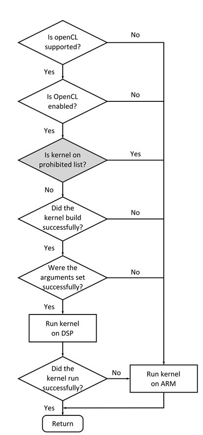
Example of OpenCL offload
Here is a simple image processing example, using OpenCL dispatch via Transparent API (Color-to-Gray, Gaussian Blur and Canny kernels).
#include <opencv2/imgproc/imgproc.hpp>
#include <opencv2/highgui/highgui.hpp>
#include <opencv2/core/ocl.hpp>
#include <time.h>
#include <unistd.h>
/* Time difference calculation, in ms units */
double tdiff_calc(struct timespec &tp_start, struct timespec &tp_end)
{
return (double)(tp_end.tv_nsec -tp_start.tv_nsec) * 0.000001 + (double)(tp_end.tv_sec - tp_start.tv_sec) * 1000.0;
}
using namespace cv;
int main(int argc, char** argv)
{
struct timespec tp0, tp1, tp2, tp3;
UMat img, gray;
imread("lena.png", 1).copyTo(img);
clock_gettime(CLOCK_MONOTONIC, &tp0);
cvtColor(img, gray, COLOR_BGR2GRAY);
clock_gettime(CLOCK_MONOTONIC, &tp1);
GaussianBlur(gray, gray, Size(5, 5), 1.25);
clock_gettime(CLOCK_MONOTONIC, &tp2);
Canny(gray, gray, 0, 30);
clock_gettime(CLOCK_MONOTONIC, &tp3);
printf ("BGR2GRAY tdiff=%lf ms \n", tdiff_calc(tp0, tp1));
printf ("GaussBlur tdiff=%lf ms \n", tdiff_calc(tp1, tp2));
printf ("Canny tdiff=%lf ms \n", tdiff_calc(tp2, tp3));
imwrite("canny_proc.jpg", gray);
return 0;
}
It can be compiled on target (AM57xx), using following command:
g++ -I/usr/local/include/opencv -I/usr/local/include/opencv2 -L/usr/local/lib/ -g -o canny_ex1 canny_ex1.cpp -lrt -lopencv_core -lopencv_imgproc -lopencv_video -lopencv_features2d -lopencv_imgcodecs
Execution can be launched using following script, showing execution time with OpenCL dispatch respectively enabled and disabled:
export TI_OCL_LOAD_KERNELS_ONCHIP=Y
export TI_OCL_CACHE_KERNELS=Y
export OPENCV_OPENCL_DEVICE='TI AM57:ACCELERATOR:TI Multicore C66 DSP'
echo "OpenCL on, canny"
./canny_ex1
export OPENCV_OPENCL_DEVICE='disabled'
echo "OpenCL off, canny"
./canny_ex
Please note that the first run, with OpenCL on, has additional delay of ~1min, due to kernel compilation on AM57xx. This is constrained to first run only, if “TI_OCL_CACHE_KERNELS” environemnt variable is set. Profiling shows different execution time for DSP (OpenCL on) and A15 (OpenCL off) platforms.
OpenCL on, canny
BGR2GRAY tdiff=12.064661 ms
GaussBlur tdiff=5.948558 ms
Canny tdiff=5.788493 ms
OpenCL off, canny
BGR2GRAY tdiff=4.158085 ms
GaussBlur tdiff=2.989813 ms
Canny tdiff=9.780171 ms
A15 loading (measured with ‘top’) during repeated execution with ‘OpenCL on’, is in 50-60% range (single CPU load). A15 loading (measured with ‘top’) during repeated execution with ‘OpenCL off’, is in 150-170% range (both CPUs loaded).
It is possible to make finer grained mapping of individual kernel execution (some kernels could be mapped to DSP, others to A15 only). Here is an example:
#include <opencv2/imgproc/imgproc.hpp>
#include <opencv2/highgui/highgui.hpp>
#include <opencv2/core/ocl.hpp>
#include <time.h>
#include <unistd.h>
using namespace cv;
/* Time difference calculation, in ms units */
double tdiff_calc(struct timespec &tp_start, struct timespec &tp_end)
{
return (double)(tp_end.tv_nsec -tp_start.tv_nsec) * 0.000001 + (double)(tp_end.tv_sec - tp_start.tv_sec) * 1000.0;
}
int main(int argc, char** argv)
{
struct timespec tp0, tp1, tp2, tp3, tp4;
Mat img_mat;
UMat img, gray;
imread("lena.png", 1).copyTo(img_mat);
cv::ocl::setUseOpenCL(false); /* suspend dispatch to DSP - from now on kernels are executed on A15 only! */
clock_gettime(CLOCK_MONOTONIC, &tp0);
cvtColor(img_mat, img_mat, COLOR_BGR2GRAY);
clock_gettime(CLOCK_MONOTONIC, &tp1);
cv::ocl::setUseOpenCL(true); /* resume DSP dispatch - from now on kernels, based on above decision tree, can be dispatched to DSP */
img_mat.copyTo(gray);
clock_gettime(CLOCK_MONOTONIC, &tp2);
GaussianBlur(gray, gray,Size(5, 5), 1.25);
clock_gettime(CLOCK_MONOTONIC, &tp3);
Canny(gray, gray, 0, 30);
clock_gettime(CLOCK_MONOTONIC, &tp4);
printf ("BGR2GRAY tdiff=%lf ms \n", tdiff_calc(tp0, tp1));
printf ("Copy2UMat tdiff=%lf ms \n", tdiff_calc(tp1, tp2));
printf ("GaussBlur tdiff=%lf ms \n", tdiff_calc(tp2, tp3));
printf ("Canny tdiff=%lf ms \n", tdiff_calc(tp3, tp4));
imwrite("canny_proc.jpg", gray);
return 0;
}
Unit Tests
Each function inthe OpenCV implementation has a unit test associate with the function. The following instructions show how to load and run unit tests of TI’s OpenCV implementation. The screen shots and device dependent instructions in this document are from AM57X build and run and can be used as a reference for build and run OpenCV test for any other TI devices from the above list
Unit Tests Prerequisites
OpenCV function unit test can run on any of TI devices that were mentioned above. This document describes how to run the unit test on AM57X family of TI devices. The screen shots were taken from a Tera-terminal connected to AM5728 EVM.
Prerequisites
- AM572 EVM (or other AM57X based system) with connection to the network. See here for information on AM57X EVM. For other devices use a similar EVM
- TI Processor SDK Linux prospective LINUX operating system. URL to download Processor SDK Linux prospective is below.
- File system either on a SD card (for devices with SD card interface), or mount to external server. If the file system resides on SD card, the card size should be at least 32GB.
Loading SDK and Standard Test Data
Processor SDK is available from the following locations
For AM335X -> http://www.ti.com/tool/PROCESSOR-SDK-AM335X
For AM437X -> http://www.ti.com/tool/PROCESSOR-SDK-AM437X
For AM57X -> http://www.ti.com/tool/PROCESSOR-SDK-AM57X
For DRA7XX -> http://www.ti.com/tool/processor-sdk-dra7x
For K2E -> http://www.ti.com/tool/PROCESSOR-SDK-K2E
For K2H -> http://www.ti.com/tool/PROCESSOR-SDK-K2H
For K2L -> http://www.ti.com/tool/PROCESSOR-SDK-K2L
For K2G -> http://www.ti.com/tool/PROCESSOR-SDK-K2G
Loading Standard Test Data
The standard test code data opencv_extra-master.zip can be downloaded from here
Procedure to Get the Test Data
There are multiple ways to download the data into the EVM
If the EVM has display and keyboard the user can downloaded
the data compressed file directly to the EVM and then unzip it
Otherwise download the data compressed file to a PC on the network and
use SCP or tftp or USB memory stick to move the data compressed file into the EVM.
The following screen shots show how to download the standard data compressed file into the EVM and unzip it. It assumes that there is a TFTP master server, for example Solarwinds or similar, and that the file opencv_extra-master.zip was downloaded from https://github.com/Itseez/opencv_extra/archive/master.zip and resides in the root directory of the TFTP server. The beginning of the unzip process and the end of the unzip process are shown in the screen shots as well.
The TFTP command is tftp -g -r opencv_extra-master.zip xxx.xxx.xxx.xxx where xxx.xxx.xxx.xxx stands for the IP address of the TFTP server. Note that the process takes few minutes because the file is very large. (More than 600MB)

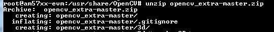
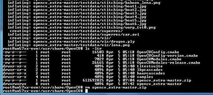
Summary of Getting the Data Steps
- Boot the EVM and login as root.
- Change directory to /usr/share/OpenCV
- Get the opencv_extra-master.zip file from a server as described above
- unzip the opencv_extra-master.zip file
- Delete the opencv_extra-master.zip file
After unzip the file a new directory *opencv_extra-master* is generated. A sub-directory *testdata* should be moved up one level.
From the OpenCV directory do the following: *mv opencv_extra-master/testdata .* . See the screen shot below.
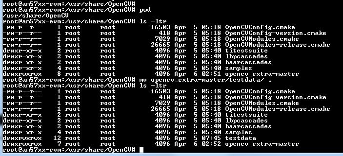
Environment Settings and Run the Tests
The script setupEnv.sh in directory /usr/share/OpenCV/titestsuite sets the environment variables that are needed for the unit tests.
From the OpenCV directory do the following: *cd titestsuit* and then *source setupEnv.sh* . See the screen shot below.
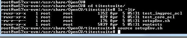
The script runtests run all the unit tests. From the titestsuit directory do *./runtests* . The unit tests starts executing. The screen will show the following:
- Currently the last three tests in the script (videoio) do not run on AM57X. The script will stuck after about 90 minutes. The user can stop the script (“control C”) or eliminate the videoio tests
- An output log file opencv_test_log.out is generated in directory /usr/share/OpenCV/titestsuite. The start of the log file looks like the following:
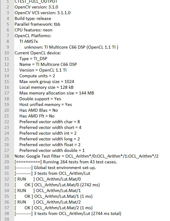
Reports and Results
Summary of accuracy test results on 66AK2H12 and AM57x platforms
| Module Name | # Of Tests | #66AK2H12 Failures | # AM57X Failures | |
|---|---|---|---|---|
| calib3d | 70 | 1 | 1 | |
| Core | 10299 | 9 | 11 | |
| features2d | 86 | 0 | 0 | |
| flann | 1 | 0 | 0 | |
| imgcodecs | 15 | 0 | 0 | |
| imgproc | 8699 | 3 | 6 | |
| ml | 26 | 0 | 0 | |
| objdetect | 9 | 0 | 0 | |
| photo | 63 | 0 | 0 | |
| shape | 3 | 0 | 0 | |
| stiching | 4 | 0 | 0 | |
| superres | 3 | 0 | 0 | |
| video | 58 | 0 | 0 | |
| videoio | 70 | 0/3 (Not built with FFMPEG/GST) | 1 |
Details of accuracy test failures results on 66AK2H12 and AM57x platforms
| Module Name | # Test | 66AK2H12 Failure | # Test | AM57X Failure |
|---|---|---|---|---|
| calib3d | 1 | Calib3d_SolvePnP (Neon) | 1 | FisheyeTest.Rectify |
| core | 1 | turnOffOpenCL::Image2D (No Image2d support in TI OpenCL) | 1 | turnOffOpenCL::Image2D (No Image2d support in TI OpenCL) |
| core | 8 | Mul (Neon) | 8 | Mul (Neon) |
| core | 1 | Add (doesn’t fail when run individually) | ||
| core | 1 | Bitwise_and (doesn’t fail when run individually) | ||
| imgproc | 1 | Imgproc_moments | 1 | Imgproc_moments |
| imgproc | 1 | Filter 2D (one test does not fail when run individually) | 1 | Erode (does not fail when run individually) |
| imgproc | 1 | Filter 2D (one test does not fail when run individually) | ||
| imgproc | 1 | Corner Harris (Not the same tests fail when run individually | 1 | Corner Harris (does not fail when run individually) |
| imgproc | 2 | CornerMinEigenVal (does not fail when run individually) | ||
| videoio | 0 | videoio.Regression (GST Library Issue) | 1 | GST library issue? |
Necessary steps to modify OpenCV framework to add more OpenCL Host side and DSP C66 optimized kernels
Primary purpose of this tutorial is to show how one can add TI DSP C66 optimized kernels to existing OpenCV framework. Necessary steps are described in below paragraphs, describing several already optimized kernels, and also how to add new and then recompile and deploy updated OpenCV in PLSDK 3.1. TI DSP specific OpenCL implementation is additional to few existing accelerators: Intel x86: SSE2/SSE4/AVX/AVX2 extensions; ARM: NEON; nVIDIA: CUDA; Generic OpenCL. Range of accelerated kernels via OpenCL is wide, e.g. OpenCV 3.10 baseline includes ~200 kernels encoded in OpenCL C. TI OpenCL (C66 core) follows 1.2 version of standard, and can execute baseline OpenCV OpenCL kernels (as-is!). But additional performance improvements can be achieved by using TI DSP OpenCL extensions (intrinsics and EDMAmgr).
Supported Platforms
OpenCV OpenCL run-time setup
OpenCV and OpenCL are already included in PLSDK 3.10. OpenCV uses run-time compilation of OpenCL kernels, so first time kernel execution is dominated by kernel compilation (later they are cached either in memory or tmp filesystem) - please note that it may take several dozens of seconds on AM5728EVM. In order to enable OpenCL acceleration inside OpenCV, following environment variable need to be set (example applies to AM57xx): export OPENCV_OPENCL_DEVICE=’TI AM57:ACCELERATOR:TI Multicore C66 DSP’
- For additional information, please refer to: https://software-dl.ti.com/mctools/esd/docs/opencl/index.html
OpenCV OpenCL development setup
OpenCV and OpenCL are already included in PLSDK 3.10.
- Development setup need to be prepared based on https://processors.wiki.ti.com/index.php/Processor_SDK_Building_The_SDK.
- When needed, source code under the work directory (e.g., arago-tmp-[toolchain]/work/am57xx_evm-linux-gnueabi/opencv/git) can be modified.
- Forced compilation can be started, after code modification:
ARAGO_BRAND=processor-sdk MACHINE=am57xx-evm bitbake opencv --force -c compile
ARAGO_BRAND=processor-sdk MACHINE=am57xx-evm bitbake opencv
- To install modified package (not all OpenCV ipk-s are changed), select updated packages in arago-tmp-[toolchain]/work/am57xx_evm-linux-gnueabi/opencv//am57xx_evm and install on target system using:
opkg install libopencv-<modulename.version.commit>-r0.tisdk4_am57xx_evm.ipk
Addition of a new kernel includes two steps: addition of Host (A15) side modification, and new DSP kernel (to be described in next chapter).
- OpenCL dispatch is attempted with macro CV_OCL_RUN_(), from top level function of specific OpenCV kernel. If OpenCV OpenCL dispatch fails, or some preconditions are not met, it falls back to Native C implementation).
- Host side OpenCL wrapper function are placed in modules/XYZ folder, in same file along with implementation for other architectures (e.g. Native C, SSE/AVX or Neon). Function can be identified with “ocl_” prefix, e.g. ocl_threshold() (modules/imgproc/src/threshold.cpp) or ocl_apply (modules/video/src/bgfg_gaussmix2.cpp). Inside this wrapper function, conditions for successful execution on DSP need to be met. This typically includes checking data types, number of channels, and/or image size.
- At this point kernel build options can be set in run-time (compilation is always done before first kernel dispatch). They are provided as string in Kernel class member variable kdefs. In this way additional optimizations can be applied (e.g. skipping parts of code, or setting parameters as constants).
- Kernel file name (where kernel is defined) is set in 2nd argument of kernel constructor, with “_oclsrc” postfix: e.g. ocl::imgproc::threshold_oclsrc - this means that kernel body is defined in ”./opencl/threshold.cl” file. This operation is performed during configuration stage of OpenCV build.
- Kernel execution is invoked via run() method (of Kernel class). All kernel arguments need to be passed before this method is invoked. This typically includes source and destination buffers, and any additional argument affecting kernel execution (scalars, temporary buffers allocated on the host side, etc.). Arguments (order, data types, etc) need to match kernel implementation. Global and local sizes used in invocation of kernel, are almost always vectors with 2 elements indicating 2D operation. Global size vector indicate total number of items to be processed, whereas local size vector indicate size of work group, i.e. number of elements (across both dimensions) in single task. In below examples, we set global size to {2,1} and local size to {1,1}, forcing creation of only two DSP tasks by OpenCL framework. In this way complete control is passed to the developer to kernel, and only ensuring that two tasks can be launched in parallel.
As a reference you can look for ocl_XYZ functions including preprocessor conditional #ifdef TIOPENCL (in modules/*/src files).
Creating OpenCL C kernel optimized for C66 core
DSP specific implementation of kernel body can be placed in existing XXX.cl or new YYY.cl file - both have to be placed in modules/ZZZ/src/opencl folder. No modification of top level CMake files are required (all .cl files present in ./opencl folder are included in compilaton). There are three options in adding new kernel implementation:
- If we decide to use existing file and kernel name, we can use macro set in kernel build options (refer to previous paragraph) - example in: modules/video/src/bgfg_gaussmix2.cpp:
...
String opts = format("-D CN=%d -D NMIXTURES=%d%s -DTIDSP_MOG2 -D SUBLINE_CACHE=%d", nchannels, nmixtures, bShadowDetection ? " -DSHADOW_DETECT" : "", subline_cache);
kernel_apply.create("mog2_kernel", ocl::video::bgfg_mog2_oclsrc, opts);
...
to select baseline or DSP specific implementation - example in: modules/video/src/opencl/bgfg_mog2.cl:
#ifdef TIDSP_MOG2
TI DSP specific implementation
...
__kernel void mog2_kernel(__global const uchar* frame, int frame_step, int frame_offset, int frame_row, int frame_col, //uchar || uchar3
__global uchar* modesUsed, //uchar
__global uchar* weight, //float
__global uchar* mean, //T_MEAN=float || float4
__global uchar* variance, //float
__global uchar* fgmask, const int fgmask_step, const int fgmask_offset, //uchar
const float alphaT, const float alpha1, const float prune,
const float c_Tb, const float c_TB, float c_Tg, const float c_varMin, //constants
const float c_varMax, const float c_varInit, const float c_tau
#ifdef SHADOW_DETECT
, const uchar c_shadowVal
#endif
)
...
#else
OPENCL generic implementation:
...
__kernel void mog2_kernel(__global const uchar* frame, int frame_step, int frame_offset, int frame_row, int frame_col, //uchar || uchar3
__global uchar* modesUsed, //uchar
__global uchar* weight, //float
__global uchar* mean, //T_MEAN=float || float4
__global uchar* variance, //float
__global uchar* fgmask, int fgmask_step, int fgmask_offset, //uchar
float alphaT, float alpha1, float prune,
float c_Tb, float c_TB, float c_Tg, float c_varMin, //constants
float c_varMax, float c_varInit, float c_tau
#ifdef SHADOW_DETECT
, uchar c_shadowVal
#endif
)
...
#endif
- Another option is to use different kernel name, and use it appropriately as mentioned in previous paragraph.
TI DSP specific implementation
__attribute__((reqd_work_group_size(1,1,1))) __kernel void tidsp_morph_erode (__global const uchar * srcptr, int src_step, int src_offset,
__global uchar * dstptr, int dst_step, int dst_offset,
int src_offset_x, int src_offset_y, int cols, int rows,
int src_whole_cols, int src_whole_rows)
...
__attribute__((reqd_work_group_size(1,1,1))) __kernel void tidsp_morph_dilate (__global const uchar * srcptr, int src_step, int src_offset,
__global uchar * dstptr, int dst_step, int dst_offset,
int src_offset_x, int src_offset_y, int cols, int rows,
int src_whole_cols, int src_whole_rows)
OpenCL generic implementation
__kernel void morph(__global const uchar * srcptr, int src_step, int src_offset,
__global uchar * dstptr, int dst_step, int dst_offset,
int src_offset_x, int src_offset_y, int cols, int rows,
int src_whole_cols, int src_whole_rows EXTRA_PARAMS)
- Third option is to create new file and use it in kernel constructor, with _oclsrc postfix (as mentioned in previous paragraph), like used in modules/imgproc/src/smooth.cpp
TI DSP specific OpenCL implementation
...
cv::String kname = format( "tidsp_gaussian" ) ;
cv::String kdefs = format("-D T=%s -D T1=%s -D cn=%d", ocl::typeToStr(type), ocl::typeToStr(depth), cn) ;
ocl::Kernel k(kname.c_str(), ocl::imgproc::gauss_oclsrc, kdefs.c_str() );
...
Implementation for this OpenCL kernel is provided in modules/imgproc/src/opencl/gauss.cl, which is a new file.
DSP kernels can use standard 1.2 OpenCL C and DSP specific extensions. OpenCL included in PLSDK 3.1 allows direct use of functions in edmamgr module. We can even use printf() in .cl files (developer does not need to bother with any additional hooks on Host side) which is very useful for development, debugging and benchmarking.
...
#ifdef TIDSP_OPENCL_VERBOSE
clk_end = __clock();
printf ("TIDSP dilate clockdiff=%d\n", clk_end - clk_start);
#endif
...
Output looks like:
[core 1] TIDSP dilate clockdiff=532646
[core 0] TIDSP dilate clockdiff=531362
OpenCV OpenCL kernels implemented specifically for DSP C66 core
Coding in OpenCL C is very close to coding in Native DSP C (cl6x). Many platform specific details are automatically resolved with OpenCL tools (like memory map handling, header file inclusion, etc) and framework (loading, buffer transfer). OpenCV is based on run-time compilation of OpenCL kernels provided in source, and preprocessed and converted to header and CPP arrays during configure stage. But, it is also possible to use off-line compilation or link with Native DSP C libraries. TI DSP OpenCL supports 1.2 standard and several DSP extensions. In order to achieve maximum performance, majority of techniques applicable in DSP C are applicable in OpenCL C:
- DSP intrinsics.
...
/* Convert from 8bpp to 16bpp so we can do SIMD of rows \*/
r0_2 = _dmpyu4(as_uchar8(r0), as_uchar8(mask1_8)); /* 8-way unsigned 8-bit X 8-bit multiplication \*/
r1_2 = _dmpyu4(as_uchar8(r1), as_uchar8(mask2_8));
r2_2 = _dmpyu4(as_uchar8(r2), as_uchar8(mask1_8));
/* Add rows 0+1, column-wise \*/
r01_lo = _dadd2(as_long(r0_2.s0123), as_long(r1_2.s0123));
r01_hi = _dadd2(as_long(r0_2.s4567), as_long(r1_2.s4567));
...
- Multi-DSP core operation - splitting work load by partitioning input data
int gid = get_global_id(0); /* 1st dimension can be used to identify DSP core */
- It is highly advisable to copy input data to L2 or even L1 memory. Use EDMA to parallelize data transfers (from DDR to/from L2) with DSP core execution
EDMA transfer framework
It is essential that EDMA operates in parallel with DSP core operation, so that DSP core always have ready data to be processed. This can be accomplished with well known “ping-pong” scheme at input end. It is possible to implement similar method at output end of operation, but typically there are much fewer write operations. Several kernels include “EDMA image processing framework”: it ensures that several consecutive image rows are transferred to L2 memory and ready to be processed by DSP core. In order to avoid redundant copies, an array of pointers to beginning of image rows is maintained. Main unit of operation is single image row. Only one image row is in-flight, both on input and output. Still, DSP processing (which is typical use case) may use multiple consecutive image rows. Examples of this framework can be found in: gauss.cl, sobel.cl, thresh.cl.
- Initialization: resetting L2 image rows
for(i = 0; i < (LINES_CACHED + 1); i ++)
{
memset ((void \*)img_lines[i], 0, MAX_LINE_SIZE);
}
- Partitioning data between DSP cores
...
int gid = get_global_id(0); /* Identify DSP core: gid is set to 0 for 1st DSP core, and 1 for 2nd DSP core \*/
...
if(gid == 0)
{ /* Upper half of image \*/
for(i = 1; i < LINES_CACHED; i ++)
{ /* Use this, one time multiple 1D1D transfers, instead of one linked transfer, to allow for fast EDMA later \*/
EdmaMgr_copy1D1D(evIN, (void \*)(srcptr + (rows - 1 + i) * cols), (void \*)(img_lines[i]), cols);
}
fetch_rd_idx = cols;
} else if(gid == 1)
{ /* Bottom half of image \*/
for(i = 0; i < LINES_CACHED; i ++)
{ /* Use this, one time multiple 1D1D transfers, instead of one linked transfer, to allow for fast EDMA later \*/
EdmaMgr_copy1D1D(evIN, (void \*)(srcptr + (rows - 1 + i) * cols), (void \*)(img_lines[i]), cols);
}
fetch_rd_idx = (rows + 1) * cols;
dest_ptr += rows * cols;
} else return;
start_rd_idx = 0;
- Main image row loop
for (int y = 0; y < rows; y ++)
{
EdmaMgr_wait(evIN);
rd_idx = start_rd_idx;
for(kk = 0; kk < LINES_CACHED; kk ++)
{
y_ptr[kk] = (uchar \*)img_lines[rd_idx];
rd_idx = (rd_idx + 1) & LINES_CACHED;
}
start_rd_idx = (start_rd_idx + 1) & LINES_CACHED;
EdmaMgr_copyFast(evIN, (void*)(srcptr + fetch_rd_idx), (void*)(img_lines[rd_idx]));
fetch_rd_idx += cols;
/**********************************************************************************/
yprev_ptr = y_ptr[0];
ycurr_ptr = y_ptr[1];
ynext_ptr = y_ptr[2];
...
/* Access L2 data directly using yprev_ptr, ycurr_ptr, ynext_ptr... \*/
Additional information about C66 specific optimizations
- C6000 Programmers guide: https://www.ti.com/lit/ug/spru198k/spru198k.pdf.
- TMS320C6000 DSP Optimization Workshop Student Guide (6.1 MB) (pdf file): https://processors.wiki.ti.com/index.php/TMS320C6000_DSP_Optimization_Workshop,
- TMS320C6000 Optimizing Compiler: https://www.ti.com/lit/ug/spru187u/spru187u.pdf
- TMS320C66x CorePac User Guide: https://www.ti.com/lit/ug/sprugw0c/sprugw0c.pdf
- TMS320C66x DSP CPU and instruction set: https://training.ti.com/system/files/docs/c66x-corepac-instruction-set-reference-guide.pdf
List of currently (PLSDK 3.1) DSP optimized OpenCV OpenCL kernels, using non-standard OpenCL extensions
OpenCL C C66 DSP kernels
Kernel name Data type - input Data type - output Host side file (full path) OpenCL C kernel file (full path) Comments erode uint8 uint8 modules/imgproc/src/morph.cpp modules/imgproc/src/opencl/morph.cl dilate uint8 uint8 modules/imgproc/src/morph.cpp modules/imgproc/src/opencl/morph.cl SobelX/SobelY uint8 int16 modules/imgproc/src/deriv.cpp modules/imgproc/src/opencl/sobel.cl threshold uint8 uint8 modules/imgproc/src/thresh.cpp modules/imgproc/src/opencl/threshold.cl GaussBlur (3x3) uint8 uint8 modules/imgproc/src/smooth.cpp modules/imgproc/src/opencl/gauss.cl convertScaleAbs int16 uint8 modules/core/src/convert.cpp modules/core/src/opencl/tidsparithm.cl Additional optimizations possible MOG2 (mixture of Gaussians) uint8 (float32 internal) uint8 (float32 internal) modules/core/src/bgfg_gaussmix2.cpp modules/core/src/opencl/bgfg_mog2.cl Additional optimizations possible |
Profiling results of DSP optimized OpenCV OpenCL kernels (PLSDK 3.1), AM5728 platform
Single channel, 1200x709, barcode ROI detection use case
Kernel name DSP optimized, cycles (per core) DSP baseline wall clock DSP optimized wall clock ARM wall clock DSP/ARM erode 883436 288.10ms 2.33ms 13.65ms 5.8x dilate 893387 290.232ms 2.36ms 13.67ms 5.8x SobelX/SobelY 586885 232.450ms 1.58ms 2.69ms 1.7x threshold 676208 3.583ms 1.72ms 0.49288ms 0.3x GaussBlur (3x3) 903159 82.601ms 2.036ms 4.289ms 2.1x convertScaleAbs 725346 112.60ms 1.73077ms 3.92ms 2.3x |
Single channel, 1920x1080. barcode ROI detection use case
Kernel name DSP optimized, cycles (per core) DSP baseline wall clock DSP optimized wall clock ARM wall clock (ms) DSP/ARM erode 2016149 358.46ms 3.762ms 74.7736ms 20.2x dilate 2020188 348.255ms 3.734ms 68.1547ms 20.2x SobelX/SobelY 1260833 281.58ms 2.38ms 13.3328ms 5.6x threshold 1535483 6.311ms 2.815ms 1.08271ms 0.4x GaussBlur (3x3) 2092713 98.61ms 3.478ms 10.0458ms 2.9x convertScaleAbs 1646050 268.272ms 3.13524ms 5.77027ms 1.8x |
Single channel, 720x576, Gesture recognition use case
Kernel name DSP optimized, cycles (per core) DSP baseline wall clock DSP optimized wall clock ARM wall clock DSP/ARM erode 567719 30.985ms 1.707ms 5.45ms 3.2x dilate 570094 31.035ms 1.750ms 5.455ms 3.2x MOG2 (mixture of Gaussians) 40307446 316.984ms 59.63ms 40.667ms 0.7x |
Alternative approach to add new OpenCL kernels at OpenCV application level
Instead of adding OpenCL kernels into OpenCV framework, it is possible to do that directly from OpenCV application. This approach might be preferred if scope and reuse of work are limited. Primary benefit is more direct control of development (avoid OpenCV framework complexities) and reduced build time (only top level application and specific kernels need to be recompiled instead of doing Yocto builds). Building the application (below example is executed on target) is straightforward:
g++ -I/usr/local/include/opencv -I/usr/local/include/opencv2 -g -c cvclapp-direct.cpp
g++ -I/usr/local/include/opencv -I/usr/local/include/opencv2 -L/usr/local/lib/ -g -o cvclapp \
cvclapp.cpp \
cvclapp-direct.o \
-lrt \
-lopencv_core \
-lopencv_imgproc \
-lopencv_highgui \
-lopencv_ml \
-lopencv_video \
-lopencv_features2d \
-lopencv_calib3d \
-lopencv_objdetect \
-lopencv_imgcodecs \
-lOpenCL -locl_util
Below two sections show how OpenCL kernels can be dispatched from OpenCV application in two different ways.
OpenCL kernel dispatch from OpenCV application, using existing OpenCV-OpenCL classes
OpenCV host side code, using OpenCV classes (defined in modules/core/src/ocl.cpp) to load and dispatch OpenCL kernels (online compilation).
#define __CL_ENABLE_EXCEPTIONS
#include <CL/cl.hpp>
#include <iostream>
#include <fstream>
#include <string>
#include <iterator>
#include <cassert>
#include "ocl_util.h"
#include <opencv2/opencv.hpp>
#include <opencv2/core/ocl.hpp>
#include <opencv2/imgproc/imgproc.hpp>
#include <opencv2/highgui/highgui.hpp>
using namespace std;
using namespace cv;
// This function is used for 2nd approach described in next section (standard OpenCL kernel dispatch)
extern void ProcRawCL(Mat &mat_src, const string &kernel_name);
int main()
{
if (!ocl::haveOpenCL())
{
cout << "OpenCL is not avaiable..." << endl;
return 0;
}
ocl::Context context;
if (!context.create(ocl::Device::TYPE_ACCELERATOR))
{
cout << "Failed creating the context..." << endl;
return 0;
}
// Select the first device
ocl::Device(context.device(0));
// Read the OpenCL kernel code into a string
ifstream ifs("kernel_inv.cl");
if (ifs.fail()) return 0;
std::string kernelSource((std::istreambuf_iterator<char>(ifs)), std::istreambuf_iterator<char>());
ocl::ProgramSource programSource(kernelSource);
// Compile the kernel code
cv::String errmsg;
cv::String buildopt = "-DDBG_VERBOSE "; // We can set various clocl build options here, e.g. define-s to compile-in/out parts of CL code
ocl::Program program = context.getProg(programSource, buildopt, errmsg);
ocl::Kernel kernel("invert_img", program);
// Transfer Mat data to the device
Mat mat_src = imread("lena.png", IMREAD_GRAYSCALE);
UMat umat_src = mat_src.getUMat(ACCESS_READ, USAGE_ALLOCATE_DEVICE_MEMORY);
cout << "Input image size: " << mat_src.size() << endl << flush;
UMat umat_dst(mat_src.size(), mat_src.type(), ACCESS_WRITE, USAGE_ALLOCATE_DEVICE_MEMORY);
kernel.args(ocl::KernelArg::ReadOnlyNoSize(umat_src), ocl::KernelArg::ReadWrite(umat_dst));
size_t globalThreads[2] = { (unsigned int)mat_src.cols, (unsigned int)mat_src.rows };
size_t localThreads[2] = { 16, 16 };
bool success = kernel.run(2, globalThreads, localThreads, false);
if (!success){
cout << "Failed running the kernel..." << endl;
return 0;
} else {
cout << "Kernel OK!" << endl;
}
GaussianBlur(umat_dst, umat_dst, Size(5, 5), 1.25);
Canny(umat_dst, umat_dst, 0, 50);
// Fetch the dst data from the device
Mat mat_dst = umat_dst.getMat(ACCESS_READ);
imwrite("out1.jpg", mat_dst);
ProcRawCL(mat_src, "kernel_direct.cl");
// imshow("src", mat_src);
// imshow("dst", mat_dst);
// waitKey();
return 1;
}
This is kernel_inv.cl file with OpenCL kernels (executed on DSP). It is loaded and compiled by above host program.
__kernel void invert_img(__global uchar* src, int src_step, int src_offset,
__global uchar* dst, int dst_step, int dst_offset,
int dst_rows, int dst_cols)
{
int x = get_global_id(0);
int y = get_global_id(1);
if (x >= dst_cols) return;
int src_index = mad24(y, src_step, x + src_offset);
int dst_index = mad24(y, dst_step, x + dst_offset);
dst[dst_index] = 255 - src[src_index];
#ifdef DBG_VERBOSE
if((x < 3) && ((y < 3) || (y >= (512 - 3)))) printf ("[x=%d][y=%d]\n", x, y);
#endif
}
OpenCL kernel dispatch from OpenCV application, using standard OpenCL dispatch with access to OpenCV data objects
This example shows how to use CMEM memory directly accessible by DSP. OpenCV Mat data structures are created to store data in CMEM, thus avoid buffer copy. For more information refer to https://software-dl.ti.com/mctools/esd/docs/opencl/memory/host-malloc-extension.html .
#define __CL_ENABLE_EXCEPTIONS
#include <CL/cl.hpp>
#include <iostream>
#include <fstream>
#include <string>
#include <iterator>
#include <cassert>
#include "ocl_util.h"
#include <opencv2/opencv.hpp>
#include <opencv2/core/ocl.hpp>
#include <opencv2/imgproc/imgproc.hpp>
#include <opencv2/highgui/highgui.hpp>
using namespace std;
using namespace cv;
using namespace cl;
const int NumElements = 512*512; // image size
const int NumWorkGroups = 256;
const int VectorElements = 4;
const int NumVecElements = NumElements / VectorElements;
const int WorkGroupSize = NumVecElements / NumWorkGroups;
void ProcRawCL(Mat &mat_src, const std::string &kernel_name)
{
//===============================================================
// Allocates memory in CMEM, directly accessible by both DSP and A15.
// This avoids buffer copying.
// Create three Mat data objects using pre-allocated CMEM memory
int bufsize = mat_src.rows * mat_src.cols;
void *ptr_cmem1 = __malloc_ddr(bufsize);
void *ptr_cmem2 = __malloc_ddr(bufsize);
void *ptr_cmem3 = __malloc_ddr(bufsize);
Mat test_mat1(mat_src.size(), CV_8UC1, ptr_cmem1);
Mat test_mat2(mat_src.size(), CV_8UC1, ptr_cmem2);
Mat test_mat3(mat_src.size(), CV_8UC1, ptr_cmem3);
mat_src.copyTo(test_mat1);
threshold(test_mat1, test_mat2, 128.0, 192.0, THRESH_BINARY);
imwrite("out_cmem1.jpg", test_mat2);
//----
mat_src.copyTo(test_mat3);
try
{
Context context(CL_DEVICE_TYPE_ACCELERATOR);
std::vector<Device> devices = context.getInfo<CL_CONTEXT_DEVICES>();
int d = 0;
std::string str;
ifstream t(kernel_name);
std::string kernelStr((istreambuf_iterator<char>(t)), istreambuf_iterator<char>());
devices[d].getInfo(CL_DEVICE_NAME, &str);
cout << "DEVICE: " << str << endl << endl;
Program::Sources source(1, std::make_pair(kernelStr.c_str(), kernelStr.length()));
Program program = Program(context, source);
program.build(devices);
Kernel kernel(program, "maskVector");
Buffer bufA (context, CL_MEM_READ_ONLY | CL_MEM_USE_HOST_PTR, bufsize, ptr_cmem2);
Buffer bufDst (context, CL_MEM_WRITE_ONLY | CL_MEM_USE_HOST_PTR, bufsize, ptr_cmem1);
kernel.setArg(0, bufA);
kernel.setArg(1, bufDst);
Event ev1;
CommandQueue Q(context, devices[d], CL_QUEUE_PROFILING_ENABLE);
Q.enqueueNDRangeKernel(kernel, NullRange, NDRange(NumVecElements), NDRange(WorkGroupSize), NULL, &ev1);
ev1.wait();
ocl_event_times(ev1, "Kernel Exec");
imwrite("out_cmem2.jpg", test_mat1);
}
catch (cl::Error err)
{
cerr << "ERROR: " << err.what() << "(" << err.err() << ", "
<< ocl_decode_error(err.err()) << ")" << endl;
}
//----
__free_ddr(ptr_cmem1);
__free_ddr(ptr_cmem2);
__free_ddr(ptr_cmem3);
//===============================================================
}
This is kernel_direct.cl OpenCL C file. Kernel maskVector is loaded, compiled and disptache by above host program
kernel void maskVector(global const uchar4* a, global uchar4* b)
{
int id = get_global_id(0);
b[id] = a[id] & (uchar4)(127, 127, 127, 127);
}
OpenCV profiling - standard procedure
Standard procedure for profiling OpenCV kernels (with OpenCL dispatch or without), is described in: https://github.com/opencv/opencv/wiki/HowToUsePerfTests In case of Processor Linux SDK on AM3/4/5 (AM57xx only supports OpenCL dispatch to DSP cores), these steps should be followed:
[EVM] cd /usr/share/OpenCV/titestsuite
[EVM] source setupEnv.txt
[LINUXBOX] Copy test vectors (copy https://github.com/opencv/opencv_extra/tree/master/testdata) to [EVM] /usr/share/OpenCV/testdata
[LINUXBOX] We need Yocto build (follow https://processors.wiki.ti.com/index.php/Processor_SDK_Building_The_SDK)
as opencv performance executables or scripts are not distributed, as standard deliverables:
From Yocto build, copy all python scripts from opencv/XYZ/git/modules/ts/misc, to EVM folder: /usr/share/OpenCV/titestsuite
From Yocto build, copy opencv_perf_* executables from opencv/XYZ/build/bin, to EVM folder: /usr/share/OpenCV/titestsuite
[EVM] Use environment variable to enable / disable OpenCL kernel acceleration:
OPENCL off:
export OPENCV_OPENCL_DEVICE='
OPENCL on:
export TI_OCL_CACHE_KERNELS=Y
export TI_OCL_KEEP_FILES=Y
export OPENCV_OPENCL_DEVICE='TI AM57:ACCELERATOR:TI Multicore C66 DSP'
[EVM] Now we are ready to run the tests, or subsets of tests:
EXAMPLE (EVM, execute from folder /usr/share/OpenCV/titestsuite): python ./run.py -t objdetect (run objdetect module performance tests)
EXAMPLE (EVM, execute from folder /usr/share/OpenCV/titestsuite): python ./run.py -t core,imgproc (run both core and imgproc performance tests... this takes a lot of time)
EXAMPLE (EVM, execute from folder /usr/share/OpenCV/titestsuite): python ./run.py --perf_force_samples=5 -t imgproc --gtest_filter="*Sobel*" (run only Sobel filters from imgproc module)
EXAMPLE (EVM, execute from folder /usr/share/OpenCV/titestsuite): python ./run.py --gtest_list_tests -t imgproc (list all the available performance tests, for imgproc module)
EXAMPLE (EVM, execute from folder /usr/share/OpenCV/titestsuite): python ./run.py --perf_force_samples=5 -t imgproc --gtest_filter="*threshold/20*" (run single test case)
3.12. OpenVX
OpenVX
OpenVX is an open, Khronos (https://www.khronos.org/openvx/) defined standard for cross platform acceleration of computer vision applications. OpenVX enables performance and power-optimized computer vision processing, with emphasis on embedded and real-time use cases:
- advanced driver assistance systems (ADAS)
- face, body and gesture tracking
- smart video surveillance
- object and scene reconstruction
- augmented reality
- visual inspection
- robotics and more.
Though originally intended for vision only embedded applications, it may be extended in future to non-vision applications suitable for data flow representation.
TIOVX
TIOVX is TI’s implementation of OpenVX Standard.
TIOVX allows users to create vision and compute applications using OpenVX API. These OpenVX applications can be executed on TI SoCs like AM57xx (including A15 and C66 cores), following OpenVX 1.1 standard. TIOVX also provides optimized OpenVX kernels for C66x DSP. An extension API allows users to integrate their own natively developed custom kernels and call them using OpenVX APIs.
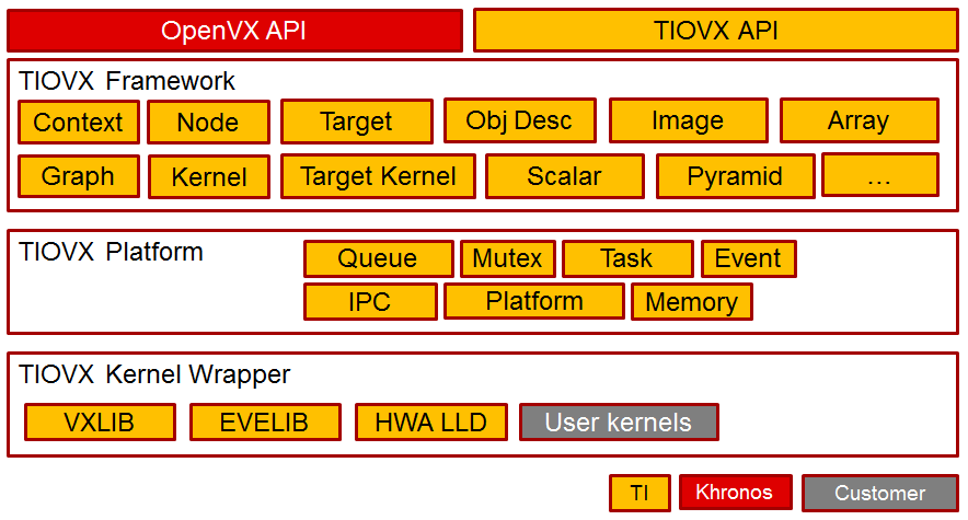
TIOVX software
| Module/Block | Description |
|---|---|
| OpenVX API | OpenVX API as defined by Khronos |
| TIOVX API | TI extensions and additional APIs in order to efficiently use OpenVX on TI platforms |
| TIOVX Framework | TI’s implementation of OpenVX spec. This layer is agnostic of underlying SoC, OS platform |
| TIOVX Platform | This layer binds TIOVX framework to a specific platform. Ex, Processor Linux SDK for AM57xx SOCs. This layer also binds TIOVX framework to a specific OS like Linux or TI-RTOS |
| TIOVX Kernel Wrapper | Kernel wrappers allow TI and customers to integrate a natively implemented kernel into the TIOVX framework. |
| TIOVX Conformance tests | OpenVX conformance test from Khronos to make sure an implementation implements OpenVX according to specification. |
There are two versions of VXLIB kernels: without BAM framework, and with BAM framework. BAM is a low level framework representing directed acyclic graph, where EDMA transfers are heavily utilized to bring 2D memory objects to higher speed L2 memory, thus improving performance almost twofold.
Current release has kernels with BAM framework. This framework achieves higher performance via heavy use of EDMA, which brings blocks of data from remote DDR memory to local L2, while DSP does the processing. List of these kernels can be checked in https://git.ti.com/processor-sdk/tiovx/trees/master/kernels/openvx-core/c66x/bam.
TIOVX DSP Kernels (in VXLIB)
There are 44 kernels in current release of VXLIB (typically there are multiple implementations for different data types).
Here is complete list of DSP kernel wrappers (wrappers are part of TIOVX):
- AbsDiff
- AccumulateSquare
- Accumulate
- AccumulateWeighted
- Add
- BitwiseAnd
- BitwiseNot
- BitwiseOr
- BitwiseXor
- Box3x3
- CannyEd
- ChannelCombine
- ChannelExtract
- ColorConvert
- ConvertDepth
- Convolve
- Dilate3x3
- EqHist
- Erode3x3
- Gaussian3x3
- HalfscaleGaussian
- HarrisCorners
- Histogram
- IntegralImage
- Lut
- Magnitude
- MeanStdDev
- Median3x3
- MinMaxLoc
- Multiply
- NonLinearFilter
- Phase
- Sobel3x3
- Subtract
- Threshold
TIOVX in Processor Linux SDK on AM57xx EVM
Following TIOVX components are present in EVM filesystem:
| Type | File path | Description |
| application | /usr/bin/tiovx-app_host | Statically linked Linux application running several thousands test cases, with all available kernels and using different test vectors |
| DSP firmware | /lib/firmware/dra7-dsp1- fw.xe66.openvx, /lib/firmware/dra7-dsp 2-fw.xe66.openvx |
DSP firmware including DSP side of TIOVX framwork implementation, IPC implementation, DSP kernels (part of VXLIB DSP library) - for DSP1. This firmware is loaded at boot time, or using procedure mentioned below (to switch from OCL firmware to TIOVX firmware) |
TIOVX release 1.0.0.0 runs exclusively wrt OpenCL, as both firmwares use common resources DSP cores and CMEM memory. That is: application can be either TIOVX-based, or OpenCL -based. Future releases may remove this limitation and use static split in resources (between OpenCL and OpenVX). TIOVX needs CMEM memory with two blocks: block 0 is big DDR block for exchange of big buffers (>100MB) and block 1 (~1MB) which is used as shared memory visible from all cores to exchange shared data objects (typically in OCMC)
Switch from OpenCL to OpenVX firmware:
Run the command below to switch from OpenCL to OpenVx firmware:
reload-dsp-fw.sh tiovx # load openvx firmware and restart dsps
Run TIOVX test application
First, it is necessary to copy test vectors from https://git.ti.com/processor-sdk/tiovx/trees/master/conformance_tests/test_data to EVM filesystem (e.g. ~/tiovx/test_data).Then run following commands:
export VX_TEST_DATA_PATH=/home/root/tiovx/test_data # Set environment variable to point to location of test vectors on EVM
tiovx-app_host 2>&1 | tee log.txt # Run test application, and log output to log.txt
At the end of test (taking roughly 24mins) you can expect report like this:
...
[ N7 ] Execution time for 307200 pixels (avg = 3.584000 ms, min = 3.584000 ms, max = 3.584000 ms)
[ N8 ] Execution time for 307200 pixels (avg = 171.797000 ms, min = 171.797000 ms, max = 171.797000 ms)
[ N9 ] Execution time for 307200 pixels (avg = 366.952000 ms, min = 366.952000 ms, max = 366.952000 ms)
[ G4 ] Execution time for 307200 pixels (avg = 500.146000 ms, min = 500.146000 ms, max = 500.146000 ms)
[ N1 ] Execution time for 256 pixels (avg = 0.278000 ms, min = 0.278000 ms, max = 0.278000 ms)
[ N2 ] Execution time for 256 pixels (avg = 0.230000 ms, min = 0.230000 ms, max = 0.230000 ms)
[ N3 ] Execution time for 256 pixels (avg = 0.281000 ms, min = 0.281000 ms, max = 0.281000 ms)
[ N4 ] Execution time for 256 pixels (avg = 0.303000 ms, min = 0.303000 ms, max = 0.303000 ms)
[ N5 ] Execution time for 256 pixels (avg = 0.285000 ms, min = 0.285000 ms, max = 0.285000 ms)
[ G5 ] Execution time for 256 pixels (avg = 2.169000 ms, min = 2.169000 ms, max = 2.169000 ms)
[ N1 ] Execution time for 256 pixels (avg = 0.243000 ms, min = 0.243000 ms, max = 0.243000 ms)
[ N2 ] Execution time for 256 pixels (avg = 0.301000 ms, min = 0.301000 ms, max = 0.301000 ms)
[ G6 ] Execution time for 256 pixels (avg = 0.871000 ms, min = 0.871000 ms, max = 0.871000 ms)
[ N1 ] Execution time for 256 pixels (avg = 0.352000 ms, min = 0.352000 ms, max = 0.352000 ms)
[ N2 ] Execution time for 256 pixels (avg = 0.246000 ms, min = 0.246000 ms, max = 0.246000 ms)
[ N2 ] Execution time for 256 pixels (avg = 0.324000 ms, min = 0.324000 ms, max = 0.324000 ms)
[ G7 ] Execution time for 256 pixels (avg = 1.502000 ms, min = 1.502000 ms, max = 1.502000 ms)
[ N1 ] Execution time for 256 pixels (avg = 75.37000 ms, min = 75.37000 ms, max = 75.37000 ms)
[ G8 ] Execution time for 256 pixels (avg = 60.474000 ms, min = 60.474000 ms, max = 60.474000 ms)
[ DONE ] tivxMaxNodes.MaxNodes/0/few_strong_corners/MIN_DISTANCE=3.0/SENSITIVITY=0.10/GRADIENT_SIZE=3/BLOCK_SIZE=5/k=3/VX_INTERPOLATION_NEAREST_NEIGHBOR
[ -------- ] 1 tests from test case tivxMaxNodes
[ ======== ]
[ ALL DONE ] 6217 test(s) from 110 test case(s) ran
[ PASSED ] 6217 test(s)
[ FAILED ] 0 test(s)
[ DISABLED ] 7397 test(s)
To be conformant 6217 required test(s) must pass. Disabled 7397 test(s) are optional.
#REPORT: 20170927134830 ALL 13614 7397 6217 6217 6217 0 (version 1.1-20170301)
<-- main:
Please note that last ~3000 lines of test log include performance data (execution time and number of pixels processed) useful for further evaluation.
Switch from OpenVX, back to OpenCL firmware:
After finishing running the TIOVX test application, switch the firmware back to the default for OpenCL:
reload-dsp-fw.sh opencl # load opencl firmware and restart dsps
Recompile TIOVX (using Yocto build)
MACHINE=am57xx-evm bitbake arago-core-tisdk-image
MACHINE=am57xx-evm bitbake tiovx-lib-host -f -c compile
MACHINE=am57xx-evm bitbake tiovx-lib-host
MACHINE=am57xx-evm bitbake tiovx-app-host -f -c compile
MACHINE=am57xx-evm bitbake tiovx-app-host
3.13. Virtualization
Overview
Jailhouse is a static partitioning hypervisor that runs bare metal binaries. It cooperates closely with Linux. Jailhouse doesn’t emulate resources that don’t exist. It just splits existing hardware resources into isolated compartments called “cells” that are wholly dedicated to guest software programs called “inmates”. One of these cells runs the Linux OS and is known as the “root cell”. Other cells borrow CPUs and devices from the root cell as they are created.
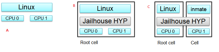
The picture above shows the jailhouse on a system a) before the jailhouse is enabled; b) after the jailhouse is enabled; c) after a cell is created.
Jailhouse consists of three parts: kernel module, hypervisor firmware and tools, which a user uses to enable the hypervisor, create a cell, load inmate binary, run and stop it. Jailhouse is an example of Asynchronous Multiprocessing (AMP) architecture. When we boot Linux on AM57XX-EVM, which has 2 ARM cores, Linux uses the both cores. After we enable hypervisor it moves Linux to the root-cell. The root cell still uses the both ARM cores. When we create a new cell, hypervisor calls cpu_down() for the ARM1 core, leaving for Linux ARM0 only. The new cell will use the ARM1 core and hardware resources dedicated for this cell in the cell configuration file.
Jailhouse is an open source project, which can be found on https://github.com/siemens/jailhouse.
Demo
Processor Linux SDK delivers Jailhouse’s prebuilt binaries. You may try it immediately after installation. This section assumes that you have already installed PLSDK, and have Linux booted on the AM572X-EVM or AM572x-IDK.
NOTE: to use Jailhouse hypervisor
- set u-boot environment variable optargs*: setenv optargs vmalloc=512M
2) use am572x-evm-jailhouse.dtb for AM572x-EVM or am572x-idk-jailhouse.dtb for AM572x-IDK
Pre-built components
As it was mentioned in the previous section, Jailhouse consists of following components, which are prebuilt and copied to the target filesystem:
- jailhouse.ko kernel module located at /lib/modules/4.9.28-<gitid>/extra/driver directory;
- jailhouse.bin - hypervisor itself located at /lib/firmware directory;
- Jailhouse management tools are located at /usr/local/libexec/jailhouse and /usr/sbin directories;
In order to create the root-cell and an inmate cell we need to provide cell configuration files. Those configuration files and example binaries are located at /usr/share/jailhouse/examples directory:
root@am57xx-evm:/usr/share/jailhouse/examples# ls -1
am572x-rtos-icss.cell
am572x-rtos-pruss.cell
am57xx-evm-ti-app.cell
am57xx-evm.cell
am57xx-pdk-leddiag.cell
icss_emac.bin
led_test.bin
linux-loader.bin
pruss.bin
ti-app.bin
where
- am57xx-evm.cell - root cell configuration file;
- ti-app.bin and am57xx-evm-ti-app.cell - bare metal inmate and its cell configuration;
- led_test.bin and am57xx-pdk-leddiag.cell - PDK led_test inmate example and its cell configuration (led_test.bin can be run on AM572x-EVM only);
- pruss.bin and am572x-rtos-pruss.cell - TI-RTOS PRUSS inmate examples and its cell configuration (pruss.bin can be run on AM572x-IDK only);
- icss_emac.bin and am572x-rtos-icss.cell - TI-RTOS ICSS-EMAC inmate example and its cell configuration (icss_emac.bin can be run on AM572x-IDK only);
- linux-loader.bin - loader required to run inmates, which start address is not 0x0;
Running the Demo on AM572x-EVM
Running bare-metal ti-app.bin
Here are the steps to run the demo:
- Boot the Linux
- Insert jailhouse.ko kernel module
root@am57xx-evm:~# modprobe jailhouse
- Enable the hypervisor using am57xx-evm.cell root-cell configuration file
root@am57xx-evm:~# jailhouse enable /usr/share/jailhouse/examples/am57xx-evm.cell
Initializing Jailhouse hypervisor v0.6 on CPU 1
Code location: 0xf0000030
Page pool usage after early setup: mem 30/4073, remap 32/131072
Initializing processors:
CPU 1... OK
CPU 0... OK
Page pool usage after late setup: mem 39/4073, remap 38/131072
Activating hypervisor
[ 4155.880217] The Jailhouse is opening.
- Create a cell for the inmate
root@am57xx-evm:~# jailhouse cell create /usr/share/jailhouse/examples/am57xx-evm-ti-app.cell
[ 5270.449687] CPU1: shutdown
[ 5270.453221] NOHZ: local_softirq_pending 20
Created cell "AM57XX-EVM-timer8-demo"
Page pool usage after cell creation: mem 51/4073, remap 38/131072
[ 5270.487970] Created Jailhouse cell "AM57XX-EVM-timer8-demo"
- Load the ti-app.bin inmate binary
root@am57xx-evm:~# jailhouse cell load 1 /usr/share/jailhouse/examples/ti-app.bin
Cell "AM57XX-EVM-timer8-demo" can be loaded
- Start the binary
root@am57xx-evm:~# jailhouse cell start 1
Hey, I'm working !!!!!!!!!!!
timer id 4fff2b01
timer value fffffc17; irq status 00000002; raw 00000002
min 00000017; avr 0000001b; max 000002c1
min 00000017; avr 0000001b; max 000000f3
min 00000017; avr 0000001b; max 000002c8
min 00000017; avr 0000001b; max 00000148
min 00000017; avr 0000001b; max 000002d4
min 00000017; avr 0000001b; max 00000158
NOTE: becase all of the components: root-cell, hypervisor and demo inmate use the same UART, there is a conflict. Once the inmate started to use the UART, Linux stops getting any input from console. To workaround this and continue to control the hypervisor, you may telnet to the EVM and issue all commands from the telnet shell. Hypervisor still will use Linux console to print it sdebug messages
- Stop the binary
root@am57xx-evm:~# jailhouse cell shutdown 1
NOTE: You may restore Linux console by killing the “/bin/login –” process from telnet session.
- destroy cell
root@am57xx-evm:~# jailhouse cell destroy 1
Closing cell "AM57XX-EVM-timer8-demo"
Page pool usage after cell destruction: mem 39/4073, remap 38/131072
[ 6201.111168] Destroyed Jailhouse cell "AM57XX-EVM-timer8-demo"
- disable hypervisor
root@am57xx-evm:~# jailhouse disable
Shutting down hypervisor
Releasing CPU 0
Releasing CPU 1
[ 6248.149728] The Jailhouse was closed.
NOTES:
You may shutdown and start the same binary multiple times. Every time you start the binary, it starts from the beginning.
If you have different binaries which use the same cell resources, you may reuse the created cell to run them. You need just shutdown the cell, load another binary and start it. If you need to run different binaries that requires different resources, you need to shutdown the running cell, destroy it, create a new one with required resources, load a new binary and start it.
Running PDK led_test.bin example
After you enable hyprevisor, create a pdk cell
root@am57xx-evm:~# jailhouse cell create /usr/share/jailhouse/examples/am57xx-pdk-leddiag.cell
[ 312.419978] CPU1: shutdown
Created cell "AM57XX-EVM-PDK-LED"
Page pool usage after cell creation: mem 54/4075, remap 38/131072
[ 312.470723] Created Jailhouse cell "AM57XX-EVM-PDK-LED"
root@am57xx-evm:~#
load the led_test.bin binary
root@am57xx-evm:~# jailhouse cell load 1 /usr/share/jailhouse/examples/led_test.bin
Cell "AM57XX-EVM-PDK-LED" can be loaded
and start it
root@am57xx-evm:~# jailhouse cell start 1
Started cell "AM57XX-EVM-PDK-LED"
root@am57xx-e
*********************************************
* LED Test *
*********************************************
Testing LED
Blinking LEDs...
Press 'y' to verify pass, 'r' to blink again,
or any other character to indicate failure: r
Blinking again
Press 'y' to verify pass, 'r' to blink again,
or any other character to indicate failure: y
Received: y
Test PASSED!
You may see blinking leds, press “r” to repeat the test.
NOTE: This example just demonstrates hypervisor’s ability to run binaries that were built outside of jailhouse source tree. This and other RTOS examples were ported for this purpose. Look to RTOS SDK documentation for description of the examples functionality.
Running the Demo on AM572x-IDK
Two TI-RTOS example applications were ported for Jailhouse hypervisor: pruss.bin and icss_emac.bin. In contrast to led_test.bin, which has its own startup code, linker script and was linked to start from address 0x0, the pruss.bin and icss_emac.bin used the TI-RTOS building infrustructure as much as possible. Therefore they are linked to EVM’s DDR address space (starting from 0x80000000 ) and their entry points are not 0x0. To support loading and running such applicaiton a special command shell be used.
To run the pruss.bin applicaton enable the hypervisor the same way as for other examples.
cd /usr/share/jailhouse/examples/
root@am57xx-evm:/usr/share/jailhouse/examples# modprobe jailhouse
root@am57xx-evm:/usr/share/jailhouse/examples# jailhouse enable ./am57xx-evm.cell
Initializing Jailhouse hypervisor on CPU 0
Code location: 0xf0000030
Page pool usage after early setup: mem 30/4075, remap 32/131072
Initializing processors:
CPU 0... OK
CPU 1... OK
Page pool usage after late setup: mem 39/4075, remap 38/131072
Activating hypervisor
[ 710.008555] The Jailhouse is opening.
Create a cell for pruss.bin
root@am57xx-evm:/usr/share/jailhouse/examples# jailhouse cell create ./am572x-rtos-pruss.cell
[ 745.067783] CPU1: shutdown
Created cell "AM572X-IDK-PRUSS"
Page pool usage after cell creation: mem 54/4075, remap 38/131072
[ 745.107324] Created Jailhouse cell "AM572X-IDK-PRUSS"
root@am57xx-evm:/usr/share/jailhouse/examples#
Use cell load command to load several required components:
root@am57xx-evm:/usr/share/jailhouse/examples# jailhouse cell load 1 linux-loader.bin -a 0 -s "kernel=0x80005128" -a 0x100 pruss.bin -a 0x80000000
Cell "AM572X-IDK-PRUSS" can be loaded
where
- linux-loader.bin is a small application provided and built by jailhouse source tree. As you can see (-a 0) it is loaded to virtual address 0x0;
- “-s “kernel=0x80005128” -a 0x100” - is the linux_loader argument loaded as string to virtual address 0x100, which instructs the linux-loader to branch to the pruss.bin 0x80005128 entry point;
- pruss.bin itself, loaded to the virtual address 0x80000000 - the address where this application is lined to;
After loading run the inmate as usual:
root@am57xx-evm:/usr/share/jailhouse/examples# jailhouse cell start 1
Started cell "AM572X-IDK-PRUSS"
root@am57xx-evm:/usr/share/jailhouse/examples# passed verify constant tbl entry for instance 1: pruNum: 0
eventwait: waiting for the INTC event from PRU
sending the INTC event to the PRU for instance: 1 , pru num: 0
eventwait: got the INTC event from PRU, count: 1
eventwait: waiting for the INTC event from PRU
sending the INTC event to the PRU for instance: 1 , pru num: 0
eventwait: got the INTC event from PRU, count: 2
eventwait: waiting for the INTC event from PRU
sending the INTC event to the PRU for instance: 1 , pru num: 0
eventwait: got the INTC event from PRU, count: 3
eventwait: waiting for the INTC event from PRU
sending the INTC event to the PRU for instance: 1 , pru num: 0
eventwait: got the INTC event from PRU, count: 4
eventwait: waiting for the INTC event from PRU
sending the INTC event to the PRU for instance: 1 , pru num: 0
eventwait: got the INTC event from PRU, count: 5
eventwait: waiting for the INTC event from PRU
Testing for instance: 1, pru num: 0 is complete
passed verify constant tbl entry for instance 1: pruNum: 1
sending the INTC event to the PRU for instance: 1 , pru num: 1
eventwait: got the INTC event from PRU, count: 1
eventwait: waiting for the INTC event from PRU
sending the INTC event to the PRU for instance: 1 , pru num: 1
eventwait: got the INTC event from PRU, count: 2
eventwait: waiting for the INTC event from PRU
sending the INTC event to the PRU for instance: 1 , pru num: 1
eventwait: got the INTC event from PRU, count: 3
eventwait: waiting for the INTC event from PRU
sending the INTC event to the PRU for instance: 1 , pru num: 1
eventwait: got the INTC event from PRU, count: 4
eventwait: waiting for the INTC event from PRU
sending the INTC event to the PRU for instance: 1 , pru num: 1
eventwait: got the INTC event from PRU, count: 5
Testing for instance: 1, pru num: 1 is complete
passed verify constant tbl entry for instance 2: pruNum: 0
eventwait2: waiting for the INTC event from PRU
sending the INTC event to the PRU for instance: 2 , pru num: 0
eventwait2: got the INTC event from PRU, count: 1
eventwait2: waiting for the INTC event from PRU
sending the INTC event to the PRU for instance: 2 , pru num: 0
eventwait2: got the INTC event from PRU, count: 2
eventwait2: waiting for the INTC event from PRU
sending the INTC event to the PRU for instance: 2 , pru num: 0
eventwait2: got the INTC event from PRU, count: 3
eventwait2: waiting for the INTC event from PRU
sending the INTC event to the PRU for instance: 2 , pru num: 0
eventwait2: got the INTC event from PRU, count: 4
eventwait2: waiting for the INTC event from PRU
sending the INTC event to the PRU for instance: 2 , pru num: 0
eventwait2: got the INTC event from PRU, count: 5
eventwait2: waiting for the INTC event from PRU
Testing for instance: 2, pru num: 0 is complete
passed verify constant tbl entry for instance 2: pruNum: 1
sending the INTC event to the PRU for instance: 2 , pru num: 1
eventwait2: got the INTC event from PRU, count: 1
eventwait2: waiting for the INTC event from PRU
sending the INTC event to the PRU for instance: 2 , pru num: 1
eventwait2: got the INTC event from PRU, count: 2
eventwait2: waiting for the INTC event from PRU
sending the INTC event to the PRU for instance: 2 , pru num: 1
eventwait2: got the INTC event from PRU, count: 3
eventwait2: waiting for the INTC event from PRU
sending the INTC event to the PRU for instance: 2 , pru num: 1
eventwait2: got the INTC event from PRU, count: 4
eventwait2: waiting for the INTC event from PRU
sending the INTC event to the PRU for instance: 2 , pru num: 1
eventwait2: got the INTC event from PRU, count: 5
Testing for instance: 2, pru num: 1 is complete
All tests have passed
You may run the icss_emac.bin in similar way using appropriate cell configuration. Note that icss_emac has different entry point - 0x80000000.
Jailhouse Performance on AM5728
To verify the real-time performance of Jailhouse Sitara AM5728 was setup to run Linux on one of the ARM Cortex A15 cores, and a TI-RTOS inmate on the other A15 core. A test was run to measure interrupt latency. Poll mode driver based application performance of an inmate should be identical to a system without virtualizationion in a static partitioning system like Jailhouse. Anything interrupt based is required to share the interrupt controller (GIC) which will introduce some interference from Linux to the real-time application. The measurements shown below over a million interrupts clearly shows the interference, and captures the upper bound at 8.8us. For the first run of interrupt latency test an unloaded Linux running on core 0 is in the first column. In the second column Linux on core 0 is running STREAM. STREAM is an external memory access benchmark that fully utilizes the number of outstanding reads and writes to memory. It is scalable from individual processors to clusters supercomputers, here it is used at the processor level. It was chosen as representative of a worst case memory access behaviour of a Linux based application on a Cortex A15, essentially with a memory access profile like an optimized memorytomemory copy. In AM5728 the two Cortex A15 cores share L2 cache and access to the rest of the SoC, which the STREAM benchmark running on core 0 stresses while core 1 access GIC registers to respond to the interrupt.
| Unloaded Linux on core 0 | Linux Running STREAM benchmark on core 0 | |
|---|---|---|
Interrutp count
Bucket 1.6 us - 3.2 us
|
99.3756% | 33.9323% |
Interrutp count
Bucket 3.2 us - 6.4 us
|
0.6244% | 66.0632% |
Interrutp count
Bucket 6.4 us - 12.8
us
|
none | 0.0045% |
| Minimum interrupt latency | 2.2 microseconds | 1.8 microseconds |
| Maximim interrupt latency | 5.0 microseconds | 8.8 microseconds |
Table: Interrupt latency of a bare metal inmate (core 1)
Building Jailhouse from Sources
Jailhouse sources are located at $TI_SDK_PATH/board-support/extra-drivers/jailhouse-0.7 directory. The directory contains the following subdirectories:
- Documentation
- ci - configuration files for different platforms. *Copy the jailhouse-config-am57xx-evm.h file into hypervisor/include/jailhouse directory and rename it to config.h*
- configs - cell configuration files.
- driver - jailhouse.ko kernel module code
- hypervisor - hypervisor code
- inmates - inmates demos. It also contains code for ti_app inmate example.
- scripts
- tools - jailhouse management utility
The top level SDK Makefile has the jailhouse_clean, jailhouse and jailhouse_install targets which can be used to clean, build and install jailhouse to the target file system.
Building and Running the Ethercat Slave Demo
To build and run the Ethercat Slave Demo, you need to install the PLSDK-RT, PRSDK and PRU-ICSS-ETHERCAT-SLAVE builds. We assume that you already have the first two SDKs installed. The PRU-ICSS-ETHERCAT-SLAVE can be downloaded from https://software-dl.ti.com/processor-industrial-sw/esd/PRU-ICSS-ETHERCAT-SLAVE/01_00_05_00/index_FDS.html.
Once you have this SDK installed you may build Ethercat slave components.
If the am572x-ethercat.cell is not installed on target filesystem yet, build it from PLSDK-RT top level makefile “make jailhouse” and copy it to target under /usr/share/jailhouse/examples.
To build the ethercat_slave_demo.bin:
- Modify the IA_SDK_HOME at ~/ti/processor_sdk_rtos_am57xx_[version]/demos/jailhouse-inmate/rtos/ethercat_slave_demo/Makefile to point to the install directory of PRU-ICSS-ETHERCAT-SLAVE.
- At ~/ti/processor_sdk_rtos_am57xx_[version]/demos/jailhouse-inmate/makefile: add ethercat_slave_demo* entries as pruss-test/icss-emac-test to the end of the makefile
ethercat_slave_demo:
$(MAKE) -C ./rtos/ethercat_slave_demo
ethercat_slave_demo_clean:
$(MAKE) -C ./rtos/ethercat_slave_demo clean
ethercat_slave_demo_install:
$(MAKE) -C ./rtos/ethercat_slave_demo install
- cd ~/ti/processor_sdk_rtos_am57xx_[version]/
- source setupenv.sh
- cd ~/ti/processor_sdk_rtos_am57xx_[version]/demos/jailhouse-inmate
- source setenv.sh
- make ethercat_slave_demo
After the steps above, copy ethercat_slave_demo.bin to target under /usr/share/jailhouse/examples.
To run the inmate refer to the instructions for **Running the Demo on AM572x-IDK** . Be aware that the inmate start address is 0x80000000. So, you need to use it as a parameter at the “jailhouse cell load” command:
jailhouse cell load 1 linux-loader.bin -a 0 -s "kernel=0x80000000" -a 0x100 ethercat_slave_demo.bin -a 0x80000000
Procedure to check two-way communication between the slave inmate and the master station:
- Refer to https://processors.wiki.ti.com/index.php/PRU_ICSS_EtherCAT#Running_EtherCAT_Slave_Application to setup Ethercat master.
- Master: Online write [data] to RxPDO 32Bit Output. After this, the slave should report the corresponding value via Board_setDigOutput. The value can be checked with “devmem2 0xeef00000” also.
- Slave: devmem2 0xeef00004 b [data]. After this, Master should display the corresponding value in TXPDO 32Bit Input.
Jailhouse Internals
This section gives some Jailhouse details and required kernel modifications.
Linux Kernel Modifications
In order to run hypervisor itself and inmates Jailhouse requires additional nodes in kernel dtb. See the am572x-evm-jailhouse.dts and am572x-idk-jailhouse.dts. They add required nodes or modify existing nodes of the default am57xx-evm-reva3.dts and am57xx-idk.dts DTS files.
Memory Reservation
Linux kernel has to reserve some memory for jailhouse hypervisor and for inmate. This memory has to be reserver statically. In this release we reserved 16MB of physical memory for hypervisor and 16MB for inmates.
/ {
reserved-memory {
jailhouse: jailhouse@ef000000 {
reg = <0x0 0xef000000 0x0 0x1000000>;
no-map;
status = "okay";
};
jh_inmate: jh_inmate@ee000000 {
reg = <0x0 0xee000000 0x0 0x1000000>;
no-map;
status = "okay";
};
};
};
Hardware Modules Reservation
Linux kernel enables all SOC HW modules which are required for its configuration. Appropriate drivers configure required clocks and initialize HW registers. For all unused IPs clocks are not configured. Also kernel power management can put a module into the sleep mode. A jailhouse inmate doesn’t share the same hardware module with Linux kernel (except debug UART). But the inmate doesn’t configure required clocks and doesn’t deal with power domains. So, we still relay on Linux kernel (at least at the current release) to configure clocks to inmate HW modules. If we want to use some hardware modules for an inmate, we have to tell kernel about this in advance.
The following nodes disable using of the timer8 and uart9 by kernel. Also this restricts kernel to put those IPs to sleep mode.
&timer8 {
status = "disabled";
ti,no-idle;
};
&uart9 {
status = "disabled";
ti,no-idle;
};
You may see other nodes in the jailhouse DTSes which reserve other IPs to be used for inmates. Thus IDK’s DTS disables nodes, which IPs are used for icss_emac and pruss inmates.
GIC Interrupt Inputs Reservation
Interrupt lines from hardware modules don’t go to ARM interrupt controller (GIC) directly. They go to a crossbar register, which selects a GIC distributor input. The selection is done dynamically by Linux kernel. Linux keeps track of all used and unused GIC inputs. If a jailhouse inmate has to use an interrupt, it has to configure the crossbar register by itself. To prevent conflicts between the Linux crossbar manager and the inmate, and give to the inmate some unused GIC input lines, which it can use, we need to reserve some of them in the kernel dts.
This can be done by adding GIC input numbers to the “ti,irqs-skip” property of the “crossbar_mpu:” node. Lines 134 and 135 are added to the following node.
crossbar_mpu: crossbar@4a002a48 {
ti,irqs-skip = <10 133 134 135 139 140>;
};
Note: The icss_emac.bin application uses much more interrupt lines. Thats is why IDK’s dtb skips aditional interrupts.
crossbar_mpu: crossbar@4a002a48 {
ti,irqs-skip = <10 44 127 129 133 134 135 136 137 139 140>;
};
Root-cell configuration
When hypervisor is being enabled it creates a cell for Linux and moves it to that cell. The cell is called as “root-cell”. The cell configuration as a “*.c” file which is compiled to a special binary format “*.cell” file. The hypervisor uses the “cell” file to create a cell. The cell configuration describes memory regions and their attributes which will be used by the cell,
.mem_regions = {
/* OCMCRAM */ {
.phys_start = 0x40300000,
.virt_start = 0x40300000,
.size = 0x80000,
.flags = JAILHOUSE_MEM_READ | JAILHOUSE_MEM_WRITE |
JAILHOUSE_MEM_IO,
},
/* 0x40380000 - 0x48020000 */ {
.phys_start = 0x40380000,
.virt_start = 0x40380000,
.size = 0x7ca0000,
.flags = JAILHOUSE_MEM_READ | JAILHOUSE_MEM_WRITE |
JAILHOUSE_MEM_IO,
},
/* UART... */ {
.phys_start = 0x48020000,
.virt_start = 0x48020000,
.size = 0xe0000,//0x00001000,
.flags = JAILHOUSE_MEM_READ | JAILHOUSE_MEM_WRITE |
JAILHOUSE_MEM_IO,
},
...
/* RAM */ {
.phys_start = 0x80000000,
.virt_start = 0x80000000,
.size = 0x6F000000,
.flags = JAILHOUSE_MEM_READ | JAILHOUSE_MEM_WRITE |
JAILHOUSE_MEM_EXECUTE,
},
/* Leave hole for hypervisor */
/* RAM */ {
.phys_start = 0xF0000000,
.virt_start = 0xF0000000,
.size = 0x10000000,
.flags = JAILHOUSE_MEM_READ | JAILHOUSE_MEM_WRITE |
JAILHOUSE_MEM_EXECUTE,
},
bitmap of CPU cores dedicated for the cell,
.cpus = {
0x3,
},
bitmap of interrupt controller SPI interrupts
.irqchips = {
/* GIC */ {
.address = 0x48211000,
.pin_base = 32,
.pin_bitmap = {
0xffffffff, 0xffffffff, 0xffffffff, 0xffffffff
},
},
/* GIC */ {
.address = 0x48211000,
.pin_base = 160,
.pin_bitmap = {
0xffffffff, 0, 0, 0
},
},
},
and some other parameters. That is for all cells.
In addition to that the root cell also allocates the physical memory for the hypervisor.
.hypervisor_memory = {
.phys_start = 0xef000000,
.size = 0x1000000,
},
The “memory regions” section is used by hypervisor to create the second stage MMU translation table. Usually for root-cell the identical mapping is being used - “VA = PA”.
See the am57xx-evm.c file is the complete am57xx-evm root cell configuration.
Bare Metal Inmate Example
Jailhouse comes with inmate demos located at the inmates/demos directory. Current (v0.6) version has two demo inmates: gic-demo and uart-demo. Those are very simple bare-metal applications that demonstrates a uart and arm-timer interrupt. Those demos are common for all jailhouse platforms.
More interesting may be the ti-app, a demo made especially for AM572x SOC. The code is located at the inmate/ti_app directory.
Basically this application is a sandbox to make some experiments. The current version demonstrates of using a uart, timer and a GIC SPI interrupt (timer generates periodic interrupts). The application also has some extra code, which was used to measure interrupt latency.
As any inmate the ti-app inmate works in a cell. The am57xx-evm-ti-app.c is the cell configuration file. For this cell only ARM1 core will be used:
.cpus = {
0x2,
},
NOTE: Actually on am572 SOC, which has only 2 ARM core and Linux always uses the ARM0 core only ARM1 can be taken for an inmate.
The cell configuration has 5 memory regions:
/* UART... */ {
.phys_start = 0x48020000,
.virt_start = 0x48020000,
.size = 0x1000,
.flags = JAILHOUSE_MEM_READ | JAILHOUSE_MEM_WRITE |
JAILHOUSE_MEM_IO | JAILHOUSE_MEM_ROOTSHARED,
},
/* UART... */ {
.phys_start = 0x48424000,
.virt_start = 0x48424000,
.size = 0x1000,
.flags = JAILHOUSE_MEM_READ | JAILHOUSE_MEM_WRITE |
JAILHOUSE_MEM_IO | JAILHOUSE_MEM_ROOTSHARED,
},
/* TIMER... */ {
.phys_start = 0x48826000,
.virt_start = 0x48826000,
.size = 0x1000,
.flags = JAILHOUSE_MEM_READ | JAILHOUSE_MEM_WRITE |
JAILHOUSE_MEM_IO | JAILHOUSE_MEM_ROOTSHARED,
},
/* L4_CFG */ {
.phys_start = 0x4a000000,
.virt_start = 0x4a000000,
.size = 0xE00000,
.flags = JAILHOUSE_MEM_READ | JAILHOUSE_MEM_WRITE |
JAILHOUSE_MEM_IO | JAILHOUSE_MEM_ROOTSHARED,
},
/* RAM */ {
.phys_start = 0xee000000,
.virt_start = 0,
.size = 0x800000,
.flags = JAILHOUSE_MEM_READ | JAILHOUSE_MEM_WRITE |
JAILHOUSE_MEM_EXECUTE | JAILHOUSE_MEM_LOADABLE,
},
Two for UARTs. The first one for UART3, which is a standard EVM debug uart. The second for UART9, using of which requires some board modifications. But UART9 doesn’t conflict with Linux or hypervisor and may be more useful if the inmate needs a dedicated UART. One region for timer9 and one for access multiple configuration registers.
The last region is for RAM allocated for the inmate. Similar to root-cell memory regions configuration memory mapping for all regions except for RAM are identical (VA = PA). For the RAM region virtual address has to be ‘0’. The physical addresses of the region must be inside of the physical memory reserved for inmates in the Linux DTS file.
In the .irqchip section of the cell configuration file we reserve GIC interrupt line #134 (One of two lines reserved in the kernel DTS).
/* GIC */ {
.address = 0x48211000,
.pin_base = 160,
.pin_bitmap = {
0x00000040,
},
},
Here where #134 comes from. The 0x00000040 is the bitmask of the sixth bit. So, .pin_base(160) + .pin_bitmap(6) - 32(number of SWI and PPI interrupt) = 134.
As other jailhouse demos the ti-app uses the jailhouse startup code, which sets the inmate vector table, zeros BSS segment, sets the stack up and calls the inmate_main(). The initialization of the GIC controller is done by hypervisor. Also the hypervisor remaps GICC interface to GICV interface and intercepts all inmates accesses to GICD. It allows to read/write only GICD registers, related to the lines given in the .irq_chips section. In our case for the line #134 only.
In the inmate_main() the inmate initializes uart, sets the crossbar and calls the gic_setup() to set the inmate’s interrupt handler. The jailhouse provides inmate interrupt controller API. This can be used by inmate.
The ti-app initializes the timer and enters to the infinite loop.
Actually the inmate code has only about 100 lines and doesn’t require any more explanation.
RTOS PDK Inmates
The jailhouse demo applications and the “ti_app” are built by jailhouse’s makefile inside the jailhouse’s source tree. It is more interesting to build an inmate outside of the jailhouse source tree, using independent makefile and third party libraries. This release provides led_test, a simple example of a bare-metal application, which uses prebuilt RTOS PDK libraries and is built independently on Jailhouse. It also has ports of two TI RTOS SYSBIOS test applications - pruss and icss_emac. There are two other examples: 1) bare-metal memcp_bm - a simple application to measure memory bandwidth; 2) Ethercat_slave_demo - ported to Jailhouse example from “PRU-ICSS Industrial Software for Sitara™ Processors”. The example requires some modifications of the PRU-ICSS Industrial Software, which is not published yet. That is why the ethercat_slave_demo included here as a reference only.
The code of the applications is located on the $(SDK_INSTALL_PATH)/processor_sdk_rtos_am57xx_4_01_00_04/demos/jailhouse-inmate directory, which contains:
├── baremetal
│ ├── led
│ │ ├── led_test.c
│ │ └── makefile
│ ├── memcp_bm
│ │ ├── makefile
│ │ └── memcp_bm.c
│ └── soc
│ └── am572x
│ ├── evmAM572x
│ │ ├── entry.S
│ │ ├── gic.c
│ │ ├── linker.cmd
│ │ └── make.inc
│ └── rules.mk
├── makefile
├── rtos
│ ├── ethercat_slave_demo
│ │ ├── bios
│ │ │ ├── am572x_app.cfg
│ │ │ └── makefile
│ │ ├── Makefile
│ │ └── src
│ │ └── board_jh.c
│ ├── icss_emac
│ │ ├── bios
│ │ │ ├── icss_emac_arm_wSoCLib.cfg
│ │ │ └── makefile
│ │ ├── lnk_pruss_fw.cmd
│ │ ├── Makefile
│ │ └── src
│ │ ├── idkAM572x_ethernet_config_jh.c
│ │ └── idkAM572x_jh.c
│ ├── pru-icss
│ │ ├── bios
│ │ │ ├── makefile
│ │ │ └── pruss_arm_wSoCLib.cfg
│ │ ├── Makefile
│ │ └── src
│ │ └── idkAM572x_jh.c
│ └── Rules.mk
└── setenv.sh
Bare-metal example
The bare-metal directory has three subdirectories: soc - has common for bare-metal applications soc specific code; led - led_test application code; memcp_bm - memcp_bm code;
The soc/am572x/evmAM572x sub-directory contains:
- entry.S - startup file for an inmate;
- gic.c - has the dummy _weak_ INTCCommonIntrHandler(), which can be overridden by an actual application handler.
- linker.cmd - jailhouse requires that an inmate shall start from address “0”. It also requires that all inmates segments be located in contiguous memory. This linker.cmd is to meet these requirements.
The led directory contains:
- The main inmate led_test.c code. This file is based on $(SDK_INSTALL_PATH)/pdk_am57xx_1_0_6/packages/ti/board/diag/led/src/led_test.c diagnostic application. Because the inmate works as a virtual machine in order to use caches MMU has to be enabled. So, the application creates the MMU translation table with identical mapping and enables MMU. It also has the gic_init(), which is now used at this relese.
- makefile is to build the inmate. As you can see, it links number of brebuilt PDK libraries.
To build the led_test.bin (a jailhouse inmate has to be *.bin, but not *.out file):
- cd to $(SDK_INSTALL_PATH)/processor_sdk_rtos_am57xx_4_01_00_04 drectory
- source setupenv.sh
- cd to $(SDK_INSTALL_PATH)/processor_sdk_rtos_am57xx_4_01_00_04/demos/jailhouse-inmates
- source setenv.sh
- run make led_test
That should build the led_test.bin binary, that can be loaded to the jailhouse cell and run. As any other inmate it has to be run in a cell, created with appropriate cell configuration. In contrast to the led_test.bin, which is compiled independently on jailhouse, a corresponding cell configuration is compiled by jailhouse makefile.
The am57xx-pdk-leddiag.c cell configuration file is located in the $TI_SDK_PATH/board-support/extra-drivers/jailhouse-0.7/configs directory. Use the compiled am57xx-pdk-leddiag.cell file when you create the cell for led_test.bin inmate.
See Running the Demo on AM572x-EVM or Running the Demo on AM572x-IDK to run the inmate.
The memcp_bm is very similar to led_test. It is built in the same way as the led_test. Use the am57xx-bm.cell file from $TI_SDK_PATH/board-support/extra-drivers/jailhouse-0.7/configs to create the jailhouse cell for the memcp_bm inmate.
RTOS BIOS Examples
The pruss and icss_emac examples are located in the rtos/pruss and rtos/icss_emac directories. The structures of the both directories are identical. Each directory contains the bios and src subdirectories. The bios contains XDC type application configuration file and makefile. The configuration file is reworked copy of the original RTOS application configuration file. For example the configuration file for icss_emac inmate was ported from $(SDK_INSTALL_PATH)/ti/pdk_am57xx_1_0_7/packages/ti/drv/icss_emac/test/am572x/armv7/bios/icss_emac_arm_wSoCLib.cfg file. As far as jailhouse inmate is not responsible for board related configuration, the board library, i2c library, OCRAM MMU sections and some other unnecessary for the inmate components were removed from the configuration file.
As far as the application main function calls the board_init() function, this function as well as the Board_moduleClockInit() (with required for icss_emac application clocks) are implemented in the idkAM572x_jh.c file.
Thus the ported configuration file, the idkAM572x_jh.c and makefiles are only new files required to port RTOS SDK existing project to jailhouse inmate.
The jailhouse-inmate/Makefile has the “pruss_test” and “icss_emac_test” targets to build the BIOS inmates.
The structure of the ethercat_slave_demo example is very similar to the pruss and icss_emac examples. As far as it depends on a particular version of the “PRU-ICSS Industrial Software”, which has to be installed independently, building of the demo is not included into the top level makefile.
RTOS BIOS Porting Notes
As you can see in the previous section, the RTOS BIOS inmates has only few new files. Almost all files were reused from RTOS SDK examples. But following notes have to be considered when porting an RTOS BIOS application to a Jailhouse inmate.
Jailhouse inmate runs in a small cell. The cell is created by hypervisor, which was started from already booted Linux OS. That says that the SOC, board and most clocks are already initialized and the inmate don’t need and usually cannot touch any resources not listed in the inmate cell configuration file.
Thus the using of board and i2c libraries were removed from cponfiguration file. Also OCRAM was removed from MMU configuration.
Jailhouse hypervisor allows inmate to access certain GICD registers, but only for those interrupt lines, which are listed in the cell configuration file. The cell creating routine reconfigures GICD target registers by itself. The standard gic_init() BIOS API configures target registers for all interrupt lines. That is not permitted for an inmate. To avoid this the latest SYSBIOS release has a special feature, which allows to disable target configuration from GIC initialization function. See the following fragment at the configuration file:
var Hwi = xdc.useModule('ti.sysbios.family.arm.gic.Hwi');
Hwi.initGicd = false;
The RTOS BIOS applications are built to *.out format. RTOS loader may load this file to the board even if the image has multiple sections with their addresses spread across the entire SOC address range. The Jailhouse supports only *.bin format, and inmate may use only allocated for it memory carved out from Linux. Therefore the ported application shall use only limited memory.
Jailhouse may start an inmate that start from virtual address 0x0, but an usual RTOS application is linked to the 0x80000000 address and with different from that entry point. The Jailhouse allows to start such applications (see above). But using the linux-loader required additional node in the inmate cell configuration.
/* RAM loader */ {
.phys_start = 0xed000000,
.virt_start = 0x0,
.size = 0x10000,
.flags = JAILHOUSE_MEM_READ | JAILHOUSE_MEM_WRITE |
JAILHOUSE_MEM_EXECUTE | JAILHOUSE_MEM_LOADABLE,
},
/* RAM RTOS 224MB*/ {
.phys_start = 0xe0000000,
.virt_start = 0x80000000,
.size = 0xd000000,
.flags = JAILHOUSE_MEM_READ | JAILHOUSE_MEM_WRITE |
JAILHOUSE_MEM_EXECUTE | JAILHOUSE_MEM_LOADABLE,
},
You may see that cell configuration for icss_emac inmate configures two RAM regions:
- small one with virtual address 0x0 for the linux-loader;
- main region for the icss_emac test itself;
General Porting Notes
When you start porting your RTOS or bare-metal application to Jailhouse inmate, you have to consider several things. They are listed below. This list is not complete and has just recommendations based on common sense and previous porting experience.
- Linux always starts first before hypervisor. Linux initializes all (or almost all) common resources of SOC. Thus it initializes memory controller, clocks, interrupt controller etc. It configures PINMUX registers. In most cases it takes care about board configuration as well.
- Inmate Cell Configuration defines resources, which are available for the inmate. The ported application can use only those resources and responsible for theirs initialization only. The ported application will not run on the board it used to run, but on a different virtual board, defined by the cell configuration. Thats is why the application cannot use any common board_init or soc_init functions that may touch used by Linux resources. Inmate is a guest only.
- As it mentioned above Linux initializes Interrupt Controller and dynamically configures crossbar registers. It has to be planned ahead which interrupts inmate may use. Those interrupts has to be reserved at Linux’s dts file. Also used by the inmate interrupts have to listed in the inmate cell configuration. Hypervisor configures GIC target registers for those interrupt. Inmate is responsible only for enabling, disabling and acknowledging the interrupts.
- Linux owns I2C buses. Inmate cannot has its owe driver to control I2C bus. It is not practicable even if the both root-cell and inmate cell configurations share I2C region and Linux and the Inmate have an agreement not to use I2C at the same time. The problem is that the Linux I2C driver works in interrupt mode and if the Inmate issues an I2C transaction, Linux’s interrupt handler will be called. It brakes the Linux’s and Inmate’s I2C drivers state machines (or whatever they have).
- Using GPIO may have the same as I2C problem. It is easy to disable an entire GPIO bank from using by Linux and use it for the Inmate. But it is not practical to share the same bank by the both Linux and Inmate.