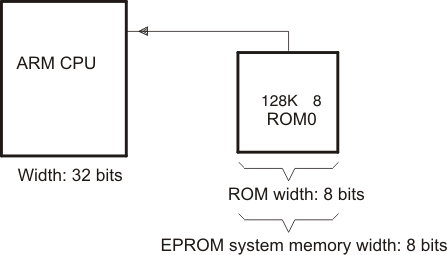
Scenario 1 shows how to build the hex conversion command file for converting an object file for the memory system shown in Figure B-1. In this system, there is one external 128K × 8-bit EPROM interfacing with a TMS470 target processor.

A object file consists of blocks of memory (sections) with assigned memory locations. Typically, all sections are not adjacent: there are holes between sections in the address space for which there is no data. Scenario 1 shows how you can use the hex conversion utility’s image mode to fill any holes before, between, or after sections with a fill value.
For this scenario, the application code resides in the program memory (ROM) on the TMS470 CPU, but the data tables used by this code reside in an off-chip EPROM.
The circuitry of the target board handles the access to the data; the native TMS470 address of 0x1000 accesses location 0x0 on the EPROM.
To satisfy the address requirements for the code, this scenario requires a linker command file that allocates sections and memory as follows:
Example 1 shows the linker command file that resolves the addresses needed in the stated specifications.