ARM Optimizing
C/C++ Compiler
v16.12.0.STS User's Guide
SPNU151N - REVISED DECEMBER 2016
6 Run-Time Environment
This chapter describes the ARM C/C++ run-time environment. To ensure successful execution of C/C++ programs, it is critical that all run-time code maintain this environment. It is also important to follow the guidelines in this chapter if you write assembly language functions that interface with C/C++ code.
6.1 Memory Model
The ARM compiler treats memory as a single linear block that is partitioned into subblocks of code and data. Each subblock of code or data generated by a C program is placed in its own continuous memory space. The compiler assumes that a full 32-bit address space is available in target memory.
NOTE
The Linker Defines the Memory MapThe linker, not the compiler, defines the memory map and allocates code and data into target memory. The compiler assumes nothing about the types of memory available, about any locations not available for code or data (holes), or about any locations reserved for I/O or control purposes. The compiler produces relocatable code that allows the linker to allocate code and data into the appropriate memory spaces. For example, you can use the linker to allocate global variables into on-chip RAM or to allocate executable code into external ROM. You can allocate each block of code or data individually into memory, but this is not a general practice (an exception to this is memory-mapped I/O, although you can access physical memory locations with C/C++ pointer types).
6.1.1 Sections
The compiler produces relocatable blocks of code and data called sections. The sections are allocated into memory in a variety of ways to conform to a variety of system configurations. For more information about sections and allocating them, see the introductory object file information in the ARM Assembly Language Tools User's Guide.
There are two basic types of sections:
-
Initialized sections contain data or executable code. Initialized sections are usually, but not always, read-only. The C/C++ compiler creates the following initialized sections:
- The .binit section contains boot time copy tables. This is a read-only section. For details on BINIT, see the ARM Assembly Language Tools User's Guide for linker command file information.
- The .init_array section contains global constructor tables.
- The .data section contains initialized global and static variables.
- The .const section contains string constants and data defined with the C/C++ qualifier const (provided the constant is not also defined as volatile). This is a read-only section.
- The .text section contains all the executable code. It also contains string literals, switch tables, and compiler-generated constants. This section is usually read-only. Note that some string literals may instead be placed in .const:.string. The placement of string literals depends on the size of the string and the use of the --embedded_constants option.
-
Uninitialized sections reserve space in memory (usually RAM). A program can use this space at run time to create and store variables. The compiler creates the following uninitialized sections:
- For EABI only, the .bss section reserves space for uninitialized global and static variables. Uninitialized variables that are also unused are usually created as common symbols (unless you specify --common=off) instead of being placed in .bss so that they can be excluded from the resulting application.
- The .stack section reserves memory for the C/C++ software stack.
- The .sysmem section reserves space for dynamic memory allocation. The reserved space is used by dynamic memory allocation routines, such as malloc, calloc, realloc, or new. If a C/C++ program does not use these functions, the compiler does not create the .sysmem section.
The assembler creates the default sections .text, .bss, and .data. You can instruct the compiler to create additional sections by using the CODE_SECTION and DATA_SECTION pragmas (see Section 5.10.5 and Section 5.10.8).
The linker takes the individual sections from different object files and combines sections that have the same name. The resulting output sections and the appropriate placement in memory for each section are listed in Table 6-1. You can place these output sections anywhere in the address space as needed to meet system requirements.
Table 6-1 Summary of Sections and Memory Placement
| Section | Type of Memory | Section | Type of Memory |
|---|---|---|---|
| .bss | RAM | .pinit | ROM or RAM |
| .cinit | ROM or RAM | .stack | RAM |
| .const | ROM or RAM | .sysmem | RAM |
| .data | RAM | .text | ROM or RAM |
| .init_array | ROM or RAM |
You can use the SECTIONS directive in the linker command file to customize the section-allocation process. For more information about allocating sections into memory, see the linker description chapter in the ARM Assembly Language Tools User's Guide.
6.1.2 C/C++ System Stack
The C/C++ compiler uses a stack to:
- Allocate local variables
- Pass arguments to functions
- Save register contents
The run-time stack grows from the high addresses to the low addresses. The compiler uses the R13 register to manage this stack. R13 is the stack pointer (SP), which points to the next unused location on the stack.
The linker sets the stack size, creates a global symbol, __STACK_SIZE, and assigns it a value equal to the stack size in bytes. The default stack size is 2048 bytes. You can change the stack size at link time by using the --stack_size option with the linker command. For more information on the --stack_size option, see the linker description chapter in the ARM Assembly Language Tools User's Guide.
At system initialization, SP is set to a designated address for the top of the stack. This address is the first location past the end of the .stack section. Since the position of the stack depends on where the .stack section is allocated, the actual address of the stack is determined at link time.
The C/C++ environment automatically decrements SP at the entry to a function to reserve all the space necessary for the execution of that function. The stack pointer is incremented at the exit of the function to restore the stack to the state before the function was entered. If you interface assembly language routines to C/C++ programs, be sure to restore the stack pointer to the same state it was in before the function was entered.
For more information about using the stack pointer, see Section 6.3; for more information about the stack, see Section 6.4.
NOTE
Stack OverflowThe compiler provides no means to check for stack overflow during compilation or at run time. A stack overflow disrupts the run-time environment, causing your program to fail. Be sure to allow enough space for the stack to grow. You can use the --entry_hook option to add code to the beginning of each function to check for stack overflow; see Section 2.15.
6.1.3 Dynamic Memory Allocation
The run-time-support library supplied with the ARM compiler contains several functions (such as malloc, calloc, and realloc) that allow you to allocate memory dynamically for variables at run time.
Memory is allocated from a global pool, or heap, that is defined in the .sysmem section. You can set the size of the .sysmem section by using the --heap_size=size option with the linker command. The linker also creates a global symbol, __SYSMEM_SIZE, and assigns it a value equal to the size of the heap in bytes. The default size is 2048 bytes. For more information on the --heap_size option, see the linker description chapter in the ARM Assembly Language Tools User's Guide.
If you use any C I/O function, the RTS library allocates an I/O buffer for each file you access. This buffer will be a bit larger than BUFSIZ, which is defined in stdio.h and defaults to 256. Make sure you allocate a heap large enough for these buffers or use setvbuf to change the buffer to a statically-allocated buffer.
Dynamically allocated objects are not addressed directly (they are always accessed with pointers) and the memory pool is in a separate section (.sysmem); therefore, the dynamic memory pool can have a size limited only by the amount of available memory in your system. To conserve space in the .bss section, you can allocate large arrays from the heap instead of defining them as global or static. For example, instead of a definition such as:
struct big table[100];
Use a pointer and call the malloc function:
struct big *table
table = (struct big *)malloc(100*sizeof(struct big));
6.2 Object Representation
For general information about data types, see Section 5.5. This section explains how various data objects are sized, aligned, and accessed.
6.2.1 Data Type Storage
Table 6-2 lists register and memory storage for various data types:
Table 6-2 Data Representation in Registers and Memory
| Data Type | Register Storage | Memory Storage |
|---|---|---|
| char, signed char | Bits 0-7 of register(1) | 8 bits aligned to 8-bit boundary |
| unsigned char, bool | Bits 0-7 of register | 8 bits aligned to 8-bit boundary |
| short, signed short | Bits 0-15 of register(1) | 16 bits aligned to 16-bit (halfword) boundary |
| unsigned short, wchar_t | Bits 0-15 of register | 16 bits aligned to 16-bit (halfword) boundary |
| int, signed int | Bits 0-31 of register | 32 bits aligned to 32-bit (word) boundary |
| unsigned int | Bits 0-31 of register | 32 bits aligned to 32-bit (word) boundary |
| long, signed long | Bits 0-31 of register | 32 bits aligned to 32-bit (word) boundary |
| unsigned long | Bits 0-31 of register | 32 bits aligned to 32-bit (word) boundary |
| long long | Even/odd register pair | 64 bits aligned to 32-bit (word) boundary(2) |
| unsigned long long | Even/odd register pair | 64 bits aligned to 32-bit (word) boundary(2) |
| float | Bits 0-31 of register | 32 bits aligned to 32-bit (word) boundary |
| double | Register pair | 64 bits aligned to 32-bit (word) boundary(2) |
| long double | Register pair | 64 bits aligned to 32-bit (word) boundary(2) |
| struct | Members are stored as their individual types require. | Members are stored as their individual types require; aligned according to the member with the most restrictive alignment requirement. |
| array | Members are stored as their individual types require. | Members are stored as their individual types require; aligned to 32-bit (word) boundary. All arrays inside a structure are aligned according to the type of each element in the array. |
| pointer to data member | Bits 0-31 of register | 32 bits aligned to 32-bit (word) boundary |
| pointer to member function | Components stored as their individual types require | 64 bits aligned to 32-bit (word) boundary |
For details about the size of an enum type, see Table 5-2.
6.2.1.1 char and short Data Types (signed and unsigned)
The char and unsigned char data types are stored in memory as a single byte and are loaded to and stored from bits 0-7 of a register (see Figure 6-1). Objects defined as short or unsigned short are stored in memory as two bytes at a halfword (2 byte) aligned address and they are loaded to and stored from bits 0-15 of a register (see Figure 6-1).
| Signed 8-bit char | |||||||||||||||||||||||||||||||
| MS | LS | ||||||||||||||||||||||||||||||
| S | S | S | S | S | S | S | S | S | S | S | S | S | S | S | S | S | S | S | S | S | S | S | S | S | S | I | I | I | I | I | I |
| 31 | 7 | 0 |
| Unsigned 8-bit char | |||||||||||||||||||||||||||||||
| MS | LS | ||||||||||||||||||||||||||||||
| 0 | 0 | 0 | 0 | 0 | 0 | 0 | 0 | 0 | 0 | 0 | 0 | 0 | 0 | 0 | 0 | 0 | 0 | 0 | 0 | 0 | 0 | 0 | 0 | 0 | U | U | U | U | U | U | U |
| 31 | 7 | 0 |
| Signed 16-bit short | |||||||||||||||||||||||||||||||
| MS | LS | ||||||||||||||||||||||||||||||
| S | S | S | S | S | S | S | S | S | S | S | S | S | S | S | S | S | I | I | I | I | I | I | I | I | I | I | I | I | I | I | I |
| 31 | 15 | 0 |
| Unsigned 16-bit short | |||||||||||||||||||||||||||||||
| MS | LS | ||||||||||||||||||||||||||||||
| 0 | 0 | 0 | 0 | 0 | 0 | 0 | 0 | 0 | 0 | 0 | 0 | 0 | 0 | 0 | 0 | U | U | U | U | U | U | U | U | U | U | U | U | U | U | U | U |
| 31 | 15 | 0 |
| LEGEND: S = sign, I = signed integer, U = unsigned integer, MS = most significant, LS = least significant |
6.2.1.2 float, int, and long Data Types (signed and unsigned)
The int, unsigned int, float, long and unsigned long data types are stored in memory as 32-bit objects at word (4 byte) aligned addresses. Objects of these types are loaded to and stored from bits 0-31 of a register, as shown in Figure 6-2. In big-endian mode, 4-byte objects are loaded to registers by moving the first byte (that is, the lower address) of memory to bits 24-31 of the register, moving the second byte of memory to bits 16-23, moving the third byte to bits 8-15, and moving the fourth byte to bits 0-7. In little-endian mode, 4-byte objects are loaded to registers by moving the first byte (that is, the lower address) of memory to bits 0-7 of the register, moving the second byte to bits 8-15, moving the third byte to bits 16-23, and moving the fourth byte to bits 24-31.
| Single-precision floating char | |||||||||||||||||||||||||||||||
| MS | LS | ||||||||||||||||||||||||||||||
| S | E | E | E | E | E | E | E | E | M | M | M | M | M | M | M | M | M | M | M | M | M | M | M | M | M | M | M | M | M | M | M |
| 31 | 23 | 0 |
| Signed 32-bit integer or long char | |||||||||||||||||||||||||||||||
| MS | LS | ||||||||||||||||||||||||||||||
| S | I | I | I | I | I | I | I | I | I | I | I | I | I | I | I | I | I | I | I | I | I | I | I | I | I | I | I | I | I | I | I |
| 31 | 0 |
| Unsigned 32-bit integer or long | |||||||||||||||||||||||||||||||
| MS | LS | ||||||||||||||||||||||||||||||
| U | U | U | U | U | U | U | U | U | U | U | U | U | U | U | U | U | U | U | U | U | U | U | U | U | U | U | U | U | U | U | U |
| 31 | 0 |
| LEGEND: S = sign, M = Mantissa, U = unsigned integer, E = exponent, I = signed integer, MS = most significant, LS = least significant |
6.2.1.3 double, long double, and long long Data Types (signed and unsigned)
Double, long double, long long and unsigned long long data types are stored in memory in a pair of registers and are always referenced as a pair. These types are stored as 64-bit objects at word (4 byte) aligned addresses. For FPA mode, the word at the lowest address contains the sign bit, the exponent, and the most significant part of the mantissa. The word at the higher address contains the least significant part of the mantissa. This is true regardless of the endianness of the target. For VFP mode, the words are ordered based upon the endianness of the target.
Objects of this type are loaded into and stored in register pairs, as shown in Figure 6-3. The most significant memory word contains the sign bit, exponent, and the most significant part of the mantissa. The least significant memory word contains the least significant part of the mantissa.
| Addressx | |||||||||||||||||||||||||||||||
| MS | |||||||||||||||||||||||||||||||
| S | E | E | E | E | E | E | E | E | E | E | E | E | M | M | M | M | M | M | M | M | M | M | M | M | M | M | M | M | M | M | M |
| 31 | 20 | 0 |
| Addressx+ 4 | |||||||||||||||||||||||||||||||
| LS | |||||||||||||||||||||||||||||||
| M | M | M | M | M | M | M | M | M | M | M | M | M | M | M | M | M | M | M | M | M | M | M | M | M | M | M | M | M | M | M | M |
| 31 | 0 |
| LEGEND: S = sign, M = mantissa, E = exponent, MS = most significant, LS = least significant |
6.2.1.4 Pointer to Data Member Types
Pointer to data member objects are stored in memory like an unsigned int (32 bit) integral type. Its value is the byte offset to the data member in the class, plus 1. The zero value is reserved to represent the NULL pointer to the data member.
6.2.1.5 Pointer to Member Function Types
Pointer to member function objects are stored as a structure with three members, and the layout is equivalent to:
struct {
 short int d;
 short int i;
 union {
 void (f) ();
 long 0; }
 };
The parameter d is the offset to be added to the beginning of the class object for this pointer. The parameter I is the index into the virtual function table, offset by 1. The index enables the NULL pointer to be represented. Its value is -1 if the function is non-virtual. The parameter f is the pointer to the member function if it is non-virtual, when I is 0. The 0 is the offset to the virtual function pointer within the class object.
6.2.1.6 Structure and Array Alignment
Structures are aligned according to the member with the most restrictive alignment requirement. Structures are padded so that the size of the structure is a multiple of its alignment. Arrays are always word aligned. Elements of arrays are stored in the same manner as if they were individual objects.
6.2.2 Bit Fields
Bit fields are the only objects that are packed within a byte. That is, two bit fields can be stored in the same byte. Bit fields can range in size from 1 to 32 bits, but they never span a 4-byte boundary.
For big-endian mode, bit fields are packed into registers from most significant bit (MSB) to least significant bit (LSB) in the order in which they are defined. Bit fields are packed in memory from most significant byte (MSbyte) to least significant byte (LSbyte). For little-endian mode, bit fields are packed into registers from the LSB to the MSB in the order in which they are defined, and packed in memory from LSbyte to MSbyte.
Here are some details about how bit fields are handled:
- Plain int bit fields are unsigned. Consider the following C code:
- Bit fields of type long long are supported.
- Bit fields are treated as the declared type.
- The size and alignment of the struct containing the bit field depends on the declared type of the bit field. For example, consider the struct:
- Unnamed bit fields affect the alignment of the struct or union. For example, consider the struct:
- Bit fields declared volatile are accessed according to the bit field's declared type. A volatile bit field reference generates exactly one reference to its storage; multiple volatile bit field accesses are not merged.
struct st
{
 int a:5;
} S;

foo()
{
 if (S.a < 0)
 bar();
}
In this example, bar () is never called as bit field 'a' is unsigned. Use signed int if you need a signed bit field.
struct st {int a:4};
This struct uses up 4 bytes and is aligned at 4 bytes.
struct st{char a:4; int :22;};
This struct uses 4 bytes and is aligned at a 4-byte boundary.
Figure 6-4 illustrates bit-field packing, using the following bit field definitions:
struct{
	int A:7
	int B:10
	int C:3
	int D:2
	int E:9
}x;
A0 represents the least significant bit of the field A; A1 represents the next least significant bit, etc. Again, storage of bit fields in memory is done with a byte-by-byte, rather than bit-by-bit, transfer.
| Big-endian register | |||||||||||||||||||||||||||||||
| MS | LS | ||||||||||||||||||||||||||||||
| A | A | A | A | A | A | A | B | B | B | B | B | B | B | B | B | B | C | C | C | D | D | E | E | E | E | E | E | E | E | E | X |
| 6 | 5 | 4 | 3 | 2 | 1 | 0 | 9 | 8 | 7 | 6 | 5 | 4 | 3 | 2 | 1 | 0 | 2 | 1 | 0 | 1 | 0 | 8 | 7 | 6 | 5 | 4 | 3 | 2 | 1 | 0 | X |
| 31 | 0 |
| Big-endian memory | |||||||||||||||||||||||||||||||
| Byte 0 | Byte 1 | Byte 2 | Byte 3 |
| A | A | A | A | A | A | A | B | B | B | B | B | B | B | B | B | B | C | C | C | D | D | E | E | E | E | E | E | E | E | E | X |
| 6 | 5 | 4 | 3 | 2 | 1 | 0 | 9 | 8 | 7 | 6 | 5 | 4 | 3 | 2 | 1 | 0 | 2 | 1 | 0 | 1 | 0 | 8 | 7 | 6 | 5 | 4 | 3 | 2 | 1 | 0 | X |
| Little-endian register | |||||||||||||||||||||||||||||||
| MS | LS | ||||||||||||||||||||||||||||||
| X | E | E | E | E | E | E | E | E | E | D | D | C | C | C | B | B | B | B | B | B | B | B | B | B | A | A | A | A | A | A | A |
| X | 8 | 7 | 6 | 5 | 4 | 3 | 2 | 1 | 0 | 1 | 0 | 2 | 1 | 0 | 9 | 8 | 7 | 6 | 5 | 4 | 3 | 2 | 1 | 0 | 6 | 5 | 4 | 3 | 2 | 1 | 0 |
| 31 | 0 |
| Little-endian memory | |||||||||||||||||||||||||||||||
| Byte 0 | Byte 1 | Byte 2 | Byte 3 |
| B | A | A | A | A | A | A | A | B | B | B | B | B | B | B | B | E | E | D | D | C | C | C | B | X | E | E | E | E | E | E | E |
| 0 | 6 | 5 | 4 | 3 | 2 | 1 | 0 | 8 | 7 | 6 | 5 | 4 | 3 | 2 | 1 | 1 | 0 | 1 | 0 | 2 | 1 | 0 | 9 | X | 8 | 7 | 6 | 5 | 4 | 3 | 2 |
| LEGEND: X = not used, MS = most significant, LS = least significant |
6.2.3 Character String Constants
In C, a character string constant is used in one of the following ways:
- To initialize an array of characters. For example:
- In an expression. For example:
char s[] = "abc";
When a string is used as an initializer, it is simply treated as an initialized array; each character is a separate initializer. For more information about initialization, see Section 6.10.
strcpy (s, "abc");
When a string is used in an expression, the string itself is defined in the .const section with the .string assembler directive, along with a unique label that points to the string; the terminating 0 byte is included. For example, the following lines define the string abc, and the terminating 0 byte (the label SL5 points to the string):
.sect ".const" SL5: .string "abc",0
String labels have the form SLn, where n is a number assigned by the compiler to make the label unique. The number begins at 0 and is increased by 1 for each string defined. All strings used in a source module are defined at the end of the compiled assembly language module.
The label SLn represents the address of the string constant. The compiler uses this label to reference the string expression.
Because strings are stored in the .const section (possibly in ROM) and shared, it is bad practice for a program to modify a string constant. The following code is an example of incorrect string use:
const char *a = "abc" a[1] = 'x'; /* Incorrect! undefined behavior */
6.3 Register Conventions
Strict conventions associate specific registers with specific operations in the C/C++ environment. If you plan to interface an assembly language routine to a C/C++ program, you must understand and follow these register conventions.
The register conventions dictate how the compiler uses registers and how values are preserved across function calls. Table 6-3 shows the types of registers affected by these conventions.Table 6-4 summarizes how the compiler uses registers and whether their values are preserved across calls. For information about how values are preserved across calls, see Section 6.4.
Table 6-3 How Register Types Are Affected by the Conventions
| Register Type | Description |
|---|---|
| Argument register | Passes arguments during a function call |
| Return register | Holds the return value from a function call |
| Expression register | Holds a value |
| Argument pointer | Used as a base value from which a function's parameters (incoming arguments) are accessed |
| Stack pointer | Holds the address of the top of the software stack |
| Link register | Contains the return address of a function call |
| Program counter | Contains the current address of code being executed |
Table 6-4 Register Usage
| Register | Alias | Usage | Preserved by Function(1) |
|---|---|---|---|
| R0 | A1 | Argument register, return register, expression register | Parent |
| R1 | A2 | Argument register, return register, expression register | Parent |
| R2 | A3 | Argument register, expression register | Parent |
| R3 | A4 | Argument register, expression register | Parent |
| R4 | V1 | Expression register | Child |
| R5 | V2 | Expression register | Child |
| R6 | V3 | Expression register | Child |
| R7 | V4, AP | Expression register, argument pointer | Child |
| R8 | V5 | Expression register | Child |
| R9 | V6 | Expression register | Child |
| R10 | V7 | Expression register | Child |
| R11 | V8 | Expression register | Child |
| R12 | V9, 1P | Expression register, instruction pointer | Parent |
| R13 | SP | Stack pointer | Child(2) |
| R14 | LR | Link register, expression register | Child |
| R15 | PC | Program counter | N/A |
| CPSR | Current program status register | Child | |
| SPSR | Saved program status register | Child |
Table 6-5 VFP Register Usage
| 32-Bit Register | 64-Bit Register | Usage | Preserved by Function(1) |
|---|---|---|---|
| FPSCR | Status register | N/A | |
| S0 | D0 | Floating-point expression, return values, pass arguments | N/A |
| S1 | |||
| S2 | D1 | Floating-point expression, return values, pass arguments | N/A |
| S3 | |||
| S4 | D2 | Floating-point expression, return values, pass arguments | N/A |
| S5 | |||
| S6 | D3 | Floating-point expression, return values, pass arguments | N/A |
| S7 | |||
| S8 | D4 | Floating-point expression, pass arguments | N/A |
| S9 | |||
| S10 | D5 | Floating-point expression, pass arguments | N/A |
| S11 | |||
| S12 | D6 | Floating-point expression, pass arguments | N/A |
| S13 | |||
| S14 | D7 | Floating-point expression, pass arguments | N/A |
| S15 | |||
| S16 | D8 | Floating-point expression | Child |
| S17 | |||
| S18 | D9 | Floating-point expression | Child |
| S19 | |||
| S20 | D10 | Floating-point expression | Child |
| S21 | |||
| S22 | D11 | Floating-point expression | Child |
| S23 | |||
| S24 | D12 | Floating-point expression | Child |
| S25 | |||
| S26 | D13 | Floating-point expression | Child |
| S27 | |||
| S28 | D14 | Floating-point expression | Child |
| S29 | |||
| S30 | D15 | Floating-point expression | Child |
| S31 | |||
| D16-D31 | Floating-point expression |
Table 6-6 Neon Register Usage
| 64-Bit Register | Quad Register | Usage | Preserved by Function(1) |
|---|---|---|---|
| D0 | Q0 | SIMD register | N/A |
| D1 | |||
| D2 | Q1 | SIMD register | N/A |
| D3 | |||
| D4 | Q2 | SIMD register | N/A |
| D5 | |||
| D6 | Q3 | SIMD register | N/A |
| D7 | |||
| D8 | Q4 | SIMD register | Child |
| D9 | |||
| D10 | Q5 | SIMD register | Child |
| D11 | |||
| D12 | Q6 | SIMD register | Child |
| D13 | |||
| D14 | Q7 | SIMD register | Child |
| D15 | |||
| D16 | Q8 | SIMD register | N/A |
| D17 | |||
| D18 | Q9 | SIMD register | N/A |
| D19 | |||
| D20 | Q10 | SIMD register | N/A |
| D21 | |||
| D22 | Q11 | SIMD register | N/A |
| D23 | |||
| D24 | Q12 | SIMD register | N/A |
| D25 | |||
| D26 | Q13 | SIMD register | N/A |
| D27 | |||
| D28 | Q14 | SIMD register | N/A |
| D29 | |||
| D30 | Q15 | SIMD register | N/A |
| D31 | |||
| FPSCR | Status register | N/A |
6.4 Function Structure and Calling Conventions
The C/C++ compiler imposes a strict set of rules on function calls. Except for special run-time support functions, any function that calls or is called by a C/C++ function must follow these rules. Failure to adhere to these rules can disrupt the C/C++ environment and cause a program to fail.
The following sections use this terminology to describe the function-calling conventions of the C/C++ compiler:
- Argument block. The part of the local frame used to pass arguments to other functions. Arguments are passed to a function by moving them into the argument block rather than pushing them on the stack. The local frame and argument block are allocated at the same time.
- Register save area. The part of the local frame that is used to save the registers when the program calls the function and restore them when the program exits the function.
- Save-on-call registers. Registers R0-R3 and R12 (alternate names are A1-A4 and V9). The called function does not preserve the values in these registers; therefore, the calling function must save them if their values need to be preserved.
- Save-on-entry registers. Registers R4-R11 and R14 (alternate names are V1 to V8 and LR). It is the called function's responsibility to preserve the values in these registers. If the called function modifies these registers, it saves them when it gains control and preserves them when it returns control to the calling function.
For details on the calling conventions in EABI mode or when using a VFP coprocessor, refer to the EABI documentation located in the ARM Information Center.
Figure 6-5 illustrates a typical function call. In this example, arguments are passed to the function, and the function uses local variables and calls another function. The first four arguments are passed to registers R0-R3. This example also shows allocation of a local frame and argument block for the called function. Functions that have no local variables and do not require an argument block do not allocate a local frame.

6.4.1 How a Function Makes a Call
A function (parent function) performs the following tasks when it calls another function (child function).
- The calling function (parent) is responsible for preserving any save-on-call registers across the call that are live across the call. (The save-on-call registers are R0-R3 and R12 (alternate names are A1-A4 and V9).)
- If the called function (child) returns a structure, the caller allocates space for the structure and passes the address of that space to the called function as the first argument.
- The caller places the first arguments in registers R0-R3, in that order. The caller moves the remaining arguments to the argument block in reverse order, placing the leftmost remaining argument at the lowest address. Thus, the leftmost remaining argument is placed at the top of the stack.
- If arguments were stored onto the argument block in step 3, the caller reserves a word in the argument block for dual-state support. (See Section 6.11 for more information.)
6.4.2 How a Called Function Responds
A called function (child function) must perform the following tasks:
- If the function is declared with an ellipsis, it can be called with a variable number of arguments. The called function pushes these arguments on the stack if they meet both of these criteria:
- The argument includes or follows the last explicitly declared argument.
- The argument is passed in a register.
- The called function pushes register values of all the registers that are modified by the function and that must be preserved upon exit of the function onto the stack. Normally, these registers are the save-on-entry registers (R4-R11 and R14 (alternate names are V1 to V8 and LR)) and the link register (R14) if the function contains calls. If the function is an interrupt, additional registers may need to be preserved. For more information, see Section 6.7.
- The called function allocates memory for the local variables and argument block by subtracting a constant from the SP. This constant is computed with the following formula:
- The called function executes the code for the function.
- If the called function returns a value, it places the value in R0 (or R0 and R1 values).
- If the called function returns a structure, it copies the structure to the memory block that the first argument, R0, points to. If the caller does not use the return value, R0 is set to 0. This directs the called function not to copy the return structure.
- The called function deallocates the frame and argument block by adding the constant computed in Step 3.
- The called function restores all registers that were saved in Step 2.
- The called function ( _f) loads the program counter (PC) with the return address.
size of all local variables + max = constant
The max argument specifies the size of all parameters placed in the argument block for each call.
In this way, the caller can be smart about telling the called function where to return the structure. For example, in the statement s = f(x), where s is a structure and f is a function that returns a structure, the caller can simply pass the address of s as the first argument and call f. The function f then copies the return structure directly into s, performing the assignment automatically.
You must be careful to properly declare functions that return structures, both at the point where they are called (so the caller properly sets up the first argument) and at the point where they are declared (so the function knows to copy the result).
The following example is typical of how a called function responds to a call:
                                 ; called function entry point
 STMFD SP!, {V1, V2, V3, LR} ; save V1, V2, V3, and LR
 SUB SP, SP, #16 ; allocate frame
 ... ; body of the function
 ADD SP, SP, #16 ; deallocate frame
 LDMFD SP!, {V1, V2, V3, PC} ; restore V1, V2, V3, and store LR
 ; in the PC, causing a return
6.4.3 C Exception Handler Calling Convention
If a C exception handler calls other functions, the following must take place:
- The handler must set its own stack pointer.
- The handler saves all of the registers not preserved by the call: R0-R3, R-12, LR (R8-R12 saved by hardware for FIQ)
- Re-entrant exception handlers must save SPSR and LR.
6.4.4 Accessing Arguments and Local Variables
A function accesses its local nonregister variables indirectly through the stack pointer (SP or R13) and its stack arguments indirectly through the argument pointer (AP). If all stack arguments can be referenced with the SP, they are, and the AP is not reserved. The SP always points to the top of the stack (the most recently pushed value) and the AP points to the leftmost stack argument (the one closest to the top of the stack). For example:
   LDR A2 [SP, #4] ; load local var from stack
 LDR A1 [AP, #0] ; load argument from stack
Since the stack grows toward smaller addresses, the local and argument data on the stack for the C/C++ function is accessed with a positive offset from the SP or the AP register.
6.5 Accessing Linker Symbols in C and C++
See the section on "Using Linker Symbols in C/C++ Applications" in the ARM Assembly Language Tools User's Guide for information about referring to linker symbols in C/C++ code.
6.6 Interfacing C and C++ With Assembly Language
The following are ways to use assembly language with C/C++ code:
- Use separate modules of assembled code and link them with compiled C/C++ modules (see Section 6.6.1).
- Use assembly language variables and constants in C/C++ source (see Section 6.6.3).
- Use inline assembly language embedded directly in the C/C++ source (see Section 6.6.5).
- Modify the assembly language code that the compiler produces (see Section 6.6.6).
6.6.1 Using Assembly Language Modules With C/C++ Code
Interfacing C/C++ with assembly language functions is straightforward if you follow the calling conventions defined in Section 6.4, and the register conventions defined in Section 6.3. C/C++ code can access variables and call functions defined in assembly language, and assembly code can access C/C++ variables and call C/C++ functions.
Follow these guidelines to interface assembly language and C:
- You must preserve any dedicated registers modified by a function. Dedicated registers include:
- Save-on-entry registers (R4-R11 (alternate names are V1 to V8 and LR))
- Stack pointer (SP or R13)
- Interrupt routines must save all the registers they use. For more information, see Section 6.7.
- When you call a C/C++ function from assembly language, load the designated registers with arguments and push the remaining arguments onto the stack as described in Section 6.4.1.
- Functions must return values correctly according to their C/C++ declarations. Double values are returned in R0 and R1, and structures are returned as described in Step 2 of Section 6.4.1. Any other values are returned in R0.
- No assembly module should use the .cinit section for any purpose other than autoinitialization of global variables. The C/C++ startup routine assumes that the .cinit section consists entirely of initialization tables. Disrupting the tables by putting other information in .cinit can cause unpredictable results.
- The compiler assigns linknames to all external objects. Thus, when you write assembly language code, you must use the same linknames as those assigned by the compiler. See Section 5.14 for details.
- Any object or function declared in assembly language that is accessed or called from C/C++ must be declared with the .def or .global directive in the assembly language modifier. This declares the symbol as external and allows the linker to resolve references to it.
If the SP is used normally, it does not need to be explicitly preserved. In other words, the assembly function is free to use the stack as long as anything that is pushed onto the stack is popped back off before the function returns (thus preserving SP).
Any register that is not dedicated can be used freely without first being saved.
Remember that a function can alter any register not designated as being preserved without having to restore it. If the contents of any of these registers must be preserved across the call, you must explicitly save them.
Likewise, to access a C/C++ function or object from assembly language, declare the C/C++ object with the .ref or .global directive in the assembly language module. This creates an undeclared external reference that the linker resolves.
6.6.2 Accessing Assembly Language Functions From C/C++
Functions defined in C++ that will be called from assembly should be defined as extern "C" in the C++ file. Functions defined in assembly that will be called from C++ must be prototyped as extern "C" in C++.
Example 6-1 illustrates a C++ function called main, which calls an assembly language function called asmfunc, Example 6-2. The asmfunc function takes its single argument, adds it to the C++ global variable called gvar, and returns the result.
Example 6-1 Calling an Assembly Language Function From a C/C++ Program
extern "C" {
extern int asmfunc(int a); /* declare external asm function */
int gvar = 0; /* define global variable */
}

void main()
{
 int I = 5;

 I = asmfunc(I); /* call function normally */
Example 6-2 Assembly Language Program Called by Example 6-1
          .global asmfunc
 .global gvar
asmfunc:
 LDR r1, gvar_a
 LDR r2, [r1, #0]
 ADD r0, r0, r2
 STR r0, [r1, #0]
 MOV pc, lr
gvar_a .field gvar, 32
In the C++ program in Example 6-1, the extern "C" declaration tells the compiler to use C naming conventions (that is, no name mangling). When the linker resolves the .global _asmfunc reference, the corresponding definition in the assembly file will match.
The parameter i is passed in R0, and the result is returned in R0. R1 holds the address of the global gvar. R2 holds the value of gvar before adding the value i to it.
6.6.3 Accessing Assembly Language Variables From C/C++
It is sometimes useful for a C/C++ program to access variables or constants defined in assembly language. There are several methods that you can use to accomplish this, depending on where and how the item is defined: a variable defined in the .bss section, a variable not defined in the .bss section, or a linker symbol.
6.6.3.1 Accessing Assembly Language Global Variables
Accessing variables from the .bss section or a section named with .usect is straightforward:
- Use the .bss or .usect directive to define the variable.
- Use the .def or .global directive to make the definition external.
- Use the appropriate linkname in assembly language.
- In C/C++, declare the variable as extern and access it normally.
Example 6-4 and Example 6-3 show how you can access a variable defined in .bss.
Example 6-3 Assembly Language Variable Program
       .bss var,4,4 ; Define the variable
 .global var ; Declare the variable as external
Example 6-4 C Program to Access Assembly Language From Example 6-3
extern int var; /* External variable */
var = 1; /* Use the variable */
6.6.3.2 Accessing Assembly Language Constants
You can define global constants in assembly language by using the .set directive in combination with either the .def or .global directive, or you can define them in a linker command file using a linker assignment statement. These constants are accessible from C/C++ only with the use of special operators.
For variables defined in C/C++ or assembly language, the symbol table contains the address of the value contained by the variable. When you access an assembly variable by name from C/C++, the compiler gets the value using the address in the symbol table.
For assembly constants, however, the symbol table contains the actual value of the constant. The compiler cannot tell which items in the symbol table are addresses and which are values. If you access an assembly (or linker) constant by name, the compiler tries to use the value in the symbol table as an address to fetch a value. To prevent this behavior, you must use the & (address of) operator to get the value (_symval). In other words, if x is an assembly language constant, its value in C/C++ is &x. See the section on "Using Linker Symbols in C/C++ Applications" in the ARM Assembly Language Tools User's Guide for more examples that use _symval.
For more about symbols and the symbol table, refer to the section on "Symbols" in the ARM Assembly Language Tools User's Guide.
You can use casts and #defines to ease the use of these symbols in your program, as in Example 6-5 and Example 6-6.
Example 6-5 Accessing an Assembly Language Constant From C
extern int table_size; /*external ref */
#define TABLE_SIZE ((int) (&table_size))
 . /* use cast to hide address-of */
 .
 .
for (I=0; i<TABLE_SIZE; ++I) /* use like normal symbol */
Example 6-6 Assembly Language Program for Example 6-5
_table_size .set	10000 ; define the constant
 .global _table_size ; make it global
Because you are referencing only the symbol's value as stored in the symbol table, the symbol's declared type is unimportant. In Example 6-5, int is used. You can reference linker-defined symbols in a similar manner.
6.6.4 Sharing C/C++ Header Files With Assembly Source
You can use the .cdecls assembler directive to share C headers containing declarations and prototypes between C and assembly code. Any legal C/C++ can be used in a .cdecls block and the C/C++ declarations will cause suitable assembly to be generated automatically, allowing you to reference the C/C++ constructs in assembly code. For more information, see the C/C++ header files chapter in the ARM Assembly Language Tools User's Guide.
6.6.5 Using Inline Assembly Language
Within a C/C++ program, you can use the asm statement to insert a single line of assembly language into the assembly language file created by the compiler. A series of asm statements places sequential lines of assembly language into the compiler output with no intervening code. For more information, see Section 5.9.
The asm statement is useful for inserting comments in the compiler output. Simply start the assembly code string with a semicolon (;) as shown below:
asm(";*** this is an assembly language comment");
NOTE
Using the asm Statement
Keep the following in mind when using the asm statement:
- Be extremely careful not to disrupt the C/C++ environment. The compiler does not check or analyze the inserted instructions.
- Avoid inserting jumps or labels into C/C++ code because they can produce unpredictable results by confusing the register-tracking algorithms that the code generator uses.
- Do not change the value of a C/C++ variable when using an asm statement. This is because the compiler does not verify such statements. They are inserted as is into the assembly code, and potentially can cause problems if you are not sure of their effect.
- Do not use the asm statement to insert assembler directives that change the assembly environment.
- Avoid creating assembly macros in C code and compiling with the --symdebug:dwarf (or -g) option. The C environment’s debug information and the assembly macro expansion are not compatible.
6.6.6 Modifying Compiler Output
You can inspect and change the compiler's assembly language output by compiling the source and then editing the assembly output file before assembling it. The C/C++ interlist feature can help you inspect compiler output. See Section 2.12.
6.7 Interrupt Handling
As long as you follow the guidelines in this section, you can interrupt and return to C/C++ code without disrupting the C/C++ environment. When the C/C++ environment is initialized, the startup routine does not enable or disable interrupts. If the system is initialized by way of a hardware reset, interrupts are disabled. If your system uses interrupts, you must handle any required enabling or masking of interrupts. Such operations have no effect on the C/C++ environment and are easily incorporated with asm statements or calling an assembly language function.
6.7.1 Saving Registers During Interrupts
When C/C++ code is interrupted, the interrupt routine must preserve the contents of all machine registers that are used by the routine or by any functions called by the routine. With the exception of banked registers, register preservation must be explicitly handled by the interrupt routine.
All banked registers are automatically preserved by the hardware (except for interrupts that are reentrant. If you write interrupt routines that are reentrant, you must add code that preserves the interrupt's banked registers.) Each interrupt type has a set of banked registers. For information about the interrupt types, see Section 5.10.15.
6.7.2 Using C/C++ Interrupt Routines
When C/C++ code is interrupted, the interrupt routine must preserve the contents of all machine registers that are used by the routine or by any functions called by the routine. Register preservation must be explicitly handled by the interrupt routine.
__interrupt void example (void)
{
...
}
If a C/C++ interrupt routine does not call any other functions, only those registers that the interrupt handler uses are saved and restored. However, if a C/C++ interrupt routine does call other functions, these functions can modify unknown registers that the interrupt handler does not use. For this reason, the routine saves all the save-on-call registers if any other functions are called. (This excludes banked registers.) Do not call interrupt handling functions directly.
Interrupts can be handled directly with C/C++ functions by using the INTERRUPT pragma or the __interrupt keyword. For information, see Section 5.10.15 and Section 5.6.2, respectively.
6.7.3 Using Assembly Language Interrupt Routines
You can handle interrupts with assembly language code as long as you follow the same register conventions the compiler does. Like all assembly functions, interrupt routines can use the stack, access global C/C++ variables, and call C/C++ functions normally. When calling C/C++ functions, be sure that any save-on-call registers are preserved before the call because the C/C++ function can modify any of these registers. You do not need to save save-on-entry registers because they are preserved by the called C/C++ function.
6.7.4 How to Map Interrupt Routines to Interrupt Vectors
NOTE
This section does not apply to Cortex-M devices.
To map Cortex-A interrupt routines to interrupt vectors you need to include a intvecs.asm file. This file will contain assembly language directives that can be used to set up the ARM's interrupt vectors with branches to your interrupt routines. Follow these steps to use this file:
- Using Example 6-7 as a guide, create intvecs.asm and include your interrupt routines. For each routine:
- At the beginning of the file, add a .global directive that names the routine.
- Modify the appropriate .word directive to create a branch to the name of your routine.
- Assemble and link intvecs.asm with your applications code and with the compiler's linker control file (lnk16.cmd or lnk32.cmd). The control file contains a SECTIONS directive that maps the .intvecs section into the memory locations 0x00-0x1F.
For example, on an ARM v4 target, if you have written a C interrupt routine for the IRQ interrupt called c_intIRQ and an assembly language routine for the FIQ interrupt called tim1_int, you should create intvecs.asm as in Example 6-7.
Example 6-7 Sample intvecs.asm File
        .if __TI_EABI_ASSEMBLER
 .asg c_intIRQ, C_INTIRQ
 .else
 .asg _c_intIRQ, C_INTIRQ
 .endif

	.global _c_int00
	.global C_INTIRQ
	.global tim1_int

	.sect ".intvecs"
	B _c_int00 ; reset interrupt
	.word 0 ; undefined instruction interrupt
	.word 0 ; software interrupt
	.word 0 ; abort (prefetch) interrupt
	.word 0 ; abort (data) interrupt
	.word 0 ; reserved
	B C_INTIRQ ; IRQ interrupt
	B tim1_int ; FIQ interrupt
6.7.5 Using Software Interrupts
A software interrupt (SWI) is a synchronous exception generated by the execution of a particular instruction. Applications use software interrupts to request services from a protected system, such as an operating system, which can perform the services only while in a supervisor mode. Some ARM documentation uses the term Supervisor Calls (SVC) instead of "software interrupt".
A C/C++ application can invoke a software interrupt by associating a software interrupt number with a function name through use of the SWI_ALIAS pragma and then calling the software interrupt as if it were a function. For information, see Section 5.10.25.
Since a call to the software interrupt function represents an invocation of the software interrupt, passing and returning data to and from a software interrupt is specified as normal function parameter passing with the following restriction:
All arguments passed to a software interrupt must reside in the four argument registers (R0-R3). No arguments can be passed by way of a software stack. Thus, only four arguments can be passed unless:
- Floating-point doubles are passed, in which case each double occupies two registers.
- Structures are returned, in which case the address of the returned structure occupies the first argument register.
For Cortex-M architectures, C SWI handlers cannot return values. Values may be returned by SWI handlers on other architectures.
The C/C++ compiler also treats the register usage of a called software interrupt the same as a called function. It assumes that all save-on-entry registers () are preserved by the software interrupt and that save-on-call registers (the remainder of the registers) can be altered by the software interrupt.
6.7.6 Other Interrupt Information
An interrupt routine can perform any task performed by any other function, including accessing global variables, allocating local variables, and calling other functions.
When you write interrupt routines, keep the following points in mind:
- It is your responsibility to handle any special masking of interrupts.
- A C/C++ interrupt routine cannot be called directly from C/C++ code.
- In a system reset interrupt, such as c_int00, you cannot assume that the run-time environment is set up; therefore, you cannot allocate local variables, and you cannot save any information on the run-time stack.
- In assembly language, remember to precede the name of a C/C++ interrupt with the appropriate linkname. For example, refer to c_int00 as _c_int00.
- When an interrupt occurs, the state of the processor (ARM or Thumb mode) is dependent on the device you are using. The compiler allows interrupt handlers to be defined in ARM or Thumb-2 mode. You should ensure the interrupt handler uses the proper mode for the device.
- The FIQ, supervisor, abort, IRQ, and undefined modes have separate stacks that are not automatically set up by the C/C++ run-time environment. If you have interrupt routines in one of these modes, you must set up the software stack for that mode. However, ARM Cortex-M processors have two stacks, and the main stack (MSP), which is used by IRQ (the only interrupt type for Cortex-M), is automatically handled by the compiler.
- Interrupt routines are not reentrant. If an interrupt routine enables interrupts of its type, it must save a copy of the return address and SPSR (the saved program status register) before doing so.
- Because a software interrupt is synchronous, the register saving conventions discussed in Section 6.7.1 can be less restrictive as long as the system is designed for this. A software interrupt routine generated by the compiler, however, follows the conventions in Section 6.7.1.
6.8 Intrinsic Run-Time-Support Arithmetic and Conversion Routines
The intrinsic run-time-support library contains a number of assembly language routines that provide arithmetic and conversion capability for C/C++ operations that the 32-bit and 16-bit instruction sets do not provide. These routines include integer division, integer modulus, and floating-point operations.
There are two versions of each of the routines:
- A 16-bit version to be called only from the 16-BIS (bit instruction set) state
- A 32-bit version only to be called from the 32-BIS state
These routines do not follow the standard C/C++ calling conventions in that the naming and register conventions are not upheld. Refer to the ARM Information Center for information on the EABI naming conventions.
6.8.1 CPSR Register and Interrupt Intrinsics
The intrinsics in Table 6-7 enable you to get/set the CPSR register and to enable/disable interrupts. All but the _call_swi() function are only available when compiling in ARM mode. Additional intrinsices for ARM assembly instructions are provided in Section 5.13.
Table 6-7 CPSR and Interrupt C/C++ Compiler Intrinsics
| C/C++ Compiler Intrinsic | Assembly Instruction |
Description |
|---|---|---|
| void _call_swi(unsigned int src); | SWI$src | Call a software interrupt. The src must be an immediate. |
| unsigned int dst = _disable_FIQ( ); | Cortex-R4/A8: MRSdst, FAULTMASK CPSIDf |
Disable FIQ interrupts and return previous FAULTMASK or CPSR setting. |
| unsigned int dst = _disable_interrupts( ); | Cortex-M0: MRSdst, PRIMASK CPSIDi Cortex-M3/M4/R4/A8: MRSdst, FAULTMASK CPSIDf |
Disable all interrupts and return previous PRIMASK or FAULTMASK setting. The assembly instructions are dependent on the architecture. |
| unsigned int dst = _disable_IRQ( ); | MRSdst, PRIMASK CPSIDi |
Disable IRQ interrupts and return previous PRIMASK setting. |
| unsigned int dst = _enable_FIQ( ); | Cortex-R4/A8: MRSdst, FAULTMASK CPSIEf |
Enable FIQ interrupts and return previous FAULTMASK or CPSR setting. |
| unsigned int dst = _enable_interrupts( ); | Cortex-M0: MRSdst, PRIMASK CPSIEi Cortex-M3/M4/R4/A8: MRSdst, FAULTMASK CPSIEf |
Enable all interrupts and return previous PRIMASK or FAULTMASK setting. The assembly instructions are dependent on the architecture. |
| unsigned int dst = _enable_IRQ( ); | MRSdst, PRIMASK CPSIEi |
Enable IRQ interrupts and return previous PRIMASK setting. |
| unsigned int dst = _get_CPSR( ); | MRSdst, CPSR | Get the CPSR register. |
| void _restore_interupts(unsigned int src); | Cortex-M0: MSR PRIMASKsrc Cortex-M3/M4: MSR FAULTMASKsrc Cortex-R4: MSR CPSR_cf ,src |
Restores interrupts to state indicated by value returned from _disable_interrupts. The assembly instructions are dependent on the architecture. |
| void _set_CPSR(unsigned int src); | MSR CPSR, src | Set the CPSR register. |
| void _set_CPSR_flg(unsigned int src); | MSRdst, CPSR | Set the CPSR flag bits. The src is rotated by the intrinsic. |
| unsigned int dst = _set_interrupt_priority( unsigned int src) ; | Cortex-M0/M3/M4 only: MRSdst, BASEPRI MSR BASEPRI,src |
Set interrupt priority and return the previous setting. |
6.9 Built-In Functions
Built-in functions are predefined by the compiler. They can be called like a regular function, but they do not require a prototype or definition. The compiler supplies the proper prototype and definition.
The ARM compiler supports the following built-in functions:
- The _ _curpc function, which returns the value of the program counter where it is called. The syntax of the function is:
- The _ _run_address_check function, which returns TRUE if the code performing the call is located at its run-time address, as assigned by the linker. Otherwise, FALSE is returned. The syntax of the function is:
void *_ _curpc(void);
int _ _run_address_check(void);
6.10 System Initialization
Before you can run a C/C++ program, you must create the C/C++ run-time environment. The C/C++ boot routine performs this task using a function called c_int00 (or _c_int00). The run-time-support source library, rts.src, contains the source to this routine in a module named boot.c (or boot.asm).
To begin running the system, the c_int00 function can be called by reset hardware. You must link the c_int00 function with the other object files. This occurs automatically when you use the --rom_model or --ram_model link option and include a standard run-time-support library as one of the linker input files.
When C/C++ programs are linked, the linker sets the entry point value in the executable output file to the symbol c_int00.
The c_int00 function performs the following tasks to initialize the environment:
- Switches to the appropriate mode, reserves space for the run-time stack, and sets up the initial value of the stack pointer (SP). The stack is aligned on a 64-bit boundary.
- Calls the function _ _TI_auto_init to perform the C/C++ autoinitialization.
- Processes the binit copy table, if present.
- Performs C autoinitialization of global/static variables. For more information, see Section 6.10.3.
- Calls C++ initialization routines for file scope construction from the global constructor table. For more information, see Section 6.10.3.6.
- Calls the main() function to run the C/C++ program.
The _ _TI_auto_init function does the following tasks:
You can replace or modify the boot routine to meet your system requirements. However, the boot routine must perform the operations listed above to correctly initialize the C/C++ environment.
6.10.1 Boot Hook Functions for System Pre-Initialization
Boot hooks are points at which you may insert application functions into the C/C++ boot process. Default boot hook functions are provided with the run-time support (RTS) library. However, you can implement customized versions of these boot hook functions, which override the default boot hook functions in the RTS library if they are linked before the run-time library. Such functions can perform any application-specific initialization before continuing with the C/C++ environment setup.
Note that the TI-RTOS operating system uses custom versions of the boot hook functions for system setup, so you should be careful about overriding these functions if you are using TI-RTOS.
The following boot hook functions are available:
__mpu_init(): This function provides an interface for initializing the MPU, if MPU support is included. The __mpu_init() function is called after the stack pointer is initialized but before any C/C++ environment setup is performed. This function should not return a value.
_system_pre_init(): This function provides a place to perform application-specific initialization. It is invoked after the stack pointer is initialized but before any C/C++ environment setup is performed. For targets that include MPU support, this function is called after __mpu_init(). By default, _system_pre_init() should return a non-zero value. The default C/C++ environment setup is bypassed if _system_pre_init() returns 0.
_system_post_cinit(): This function is invoked during C/C++ environment setup, after C/C++ global data is initialized but before any C++ constructors are called. This function should not return a value.
The _c_int00( ) initialization routine also provides a mechanism for an application to perform the setup (set I/O registers, enable/disable timers, etc.) before the C/C++ environment is initialized.
6.10.2 Run-Time Stack
The run-time stack is allocated in a single continuous block of memory and grows down from high addresses to lower addresses. The SP points to the top of the stack.
The code does not check to see if the run-time stack overflows. Stack overflow occurs when the stack grows beyond the limits of the memory space that was allocated for it. Be sure to allocate adequate memory for the stack.
The stack size can be changed at link time by using the --stack_size link option on the linker command line and specifying the stack size as a constant directly after the option.
The C/C++ boot routine shipped with the compiler sets up the user/thread mode run-time stack. If your program uses a run-time stack when it is in other operating modes, you must also allocate space and set up the run-time stack corresponding to those modes.
EABI requires that 64-bit data (type long long and long double) be aligned at 64-bits. This requires that the stack be aligned at a 64-bit boundary at function entry so that local 64-bit variables are allocated in the stack with correct alignment. The boot routine aligns the stack at a 64-bit boundary.
6.10.3 Automatic Initialization of Variables
Any global variables declared as preinitialized must have initial values assigned to them before a C/C++ program starts running. The process of retrieving these variables' data and initializing the variables with the data is called autoinitialization. Internally, the compiler and linker coordinate to produce compressed initialization tables. Your code should not access the initialization table.
6.10.3.1 Zero Initializing Variables
In ANSI C, global and static variables that are not explicitly initialized must be set to 0 before program execution. The C/C++ compiler supports preinitialization of uninitialized variables by default. This can be turned off by specifying the linker option --zero_init=off.
6.10.3.2 Direct Initialization
The compiler uses direct initialization to initialize global variables. For example, consider the following C code:
int i = 23;
int a[5] = { 1, 2, 3, 4, 5 };
The compiler allocates the variables 'i' and 'a[] to .data section and the initial values are placed directly.
        .global i
 .data
 .align 4
i:
 .field 23,32 ; i @ 0

 .global a
 .data
 .align 4
a:
 .field 1,32 ; a[0] @ 0
 .field 2,32 ; a[1] @ 32
 .field 3,32 ; a[2] @ 64
 .field 4,32 ; a[3] @ 96
 .field 5,32 ; a[4] @ 128
Each compiled module that defines static or global variables contains these .data sections. The linker treats the .data section like any other initialized section and creates an output section. In the load-time initialization model, the sections are loaded into memory and used by the program. See Section 6.10.3.5.
In the run-time initialization model, the linker uses the data in these sections to create initialization data and an additional compressed initialization table. The boot routine processes the initialization table to copy data from load addresses to run addresses. See Section 6.10.3.3.
6.10.3.3 Autoinitialization of Variables at Run Time
Autoinitializing variables at run time is the default method of autoinitialization. To use this method, invoke the linker with the --rom_model option.
Using this method, the linker creates a compressed initialization table and initialization data from the direct initialized sections in the compiled module. The table and data are used by the C/C++ boot routine to initialize variables in RAM using the table and data in ROM.
Figure 6-6 illustrates autoinitialization at run time. Use this method in any system where your application runs from code burned into ROM.

6.10.3.4 Autoinitialization Tables
The compiled object files do not have initialization tables. The variables are initialized directly . The linker, when the --rom_model option is specified, creates C auto initialization table and the initialization data. The linker creates both the table and the initialization data in an output section named .cinit.
The autoinitialization table has the following format:
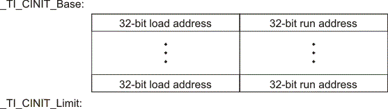
The linker defined symbols __TI_CINIT_Base and __TI_CINIT_Limit point to the start and end of the table, respectively. Each entry in this table corresponds to one output section that needs to be initialized. The initialization data for each output section could be encoded using different encoding.
The load address in the C auto initialization record points to initialization data with the following format:
| 8-bit index | Encoded data |
The first 8-bits of the initialization data is the handler index. It indexes into a handler table to get the address of a handler function that knows how to decode the following data.
The handler table is a list of 32-bit function pointers.
The encoded data that follows the 8-bit index can be in one of the following format types. For clarity the 8-bit index is also depicted for each format.
6.10.3.4.1 Length Followed by Data Format
| 8-bit index | 24-bit padding | 32-bit length (N) | N byte initialization data (not compressed) |
The compiler uses 24-bit padding to align the length field to a 32-bit boundary. The 32-bit length field encodes the length of the initialization data in bytes (N). N byte initialization data is not compressed and is copied to the run address as is.
The run-time support library has a function __TI_zero_init() to process this type of initialization data. The first argument to this function is the address pointing to the byte after the 8-bit index. The second argument is the run address from the C auto initialization record.
6.10.3.4.2 Zero Initialization Format
| 8-bit index | 24-bit padding | 32-bit length (N) |
The compiler uses 24-bit padding to align the length field to a 32-bit boundary. The 32-bit length field encodes the number of bytes to be zero initialized.
The run-time support library has a function __TI_zero_init() to process the zero initialization. The first argument to this function is the address pointing to the byte after the 8-bit index. The second argument is the run address from the C auto initialization record.
6.10.3.4.3 Run Length Encoded (RLE) Format
| 8-bit index | Initialization data compressed using run length encoding |
The data following the 8-bit index is compressed using Run Length Encoded (RLE) format. uses a simple run length encoding that can be decompressed using the following algorithm:
- Read the first byte, Delimiter (D).
- Read the next byte (B).
- If B != D, copy B to the output buffer and go to step 2.
- Read the next byte (L).
- If L == 0, then length is either a 16-bit, a 24-bit value, or we’ve reached the end of the data, read next byte (L).
- If L == 0, length is a 24-bit value or the end of the data is reached, read next byte (L).
- If L == 0, the end of the data is reached, go to step 7.
- Else L <<= 16, read next two bytes into lower 16 bits of L to complete 24-bit value for L.
- Else L <<= 8, read next byte into lower 8 bits of L to complete 16-bit value for L.
- If L == 0, length is a 24-bit value or the end of the data is reached, read next byte (L).
- Else if L > 0 and L < 4, copy D to the output buffer L times. Go to step 2.
- Else, length is 8-bit value (L).
- If L == 0, then length is either a 16-bit, a 24-bit value, or we’ve reached the end of the data, read next byte (L).
- Read the next byte (C); C is the repeat character.
- Write C to the output buffer L times; go to step 2.
- End of processing.
The run-time support library has a routine __TI_decompress_rle24() to decompress data compressed using RLE. The first argument to this function is the address pointing to the byte after the 8-bit index. The second argument is the run address from the C auto initialization record.
NOTE
RLE Decompression RoutineThe previous decompression routine, __TI_decompress_rle(), is included in the run-time-support library for decompressing RLE encodings generated by older versions of the linker.
6.10.3.4.4 Lempel-Ziv-Storer-Szymanski Compression (LZSS) Format
| 8-bit index | Initialization data compressed using LZSS |
The data following the 8-bit index is compressed using LZSS compression. The run-time support library has the routine __TI_decompress_lzss() to decompress the data compressed using LZSS. The first argument to this function is the address pointing to the byte after the 8-bit index. The second argument is the run address from the C auto initialization record.
6.10.3.4.5 Sample C Code to Process the C Autoinitialization Table
The run-time support boot routine has code to process the C autoinitialization table. The following C code illustrates how the autoinitialization table can be processed on the target.
Example 6-8 Processing the C Autoinitialization Table
typedef void (*handler_fptr)(const unsigned char *in,
unsigned char *out);

#define HANDLER_TABLE __TI_Handler_Table_Base
#pragma WEAK(HANDLER_TABLE)
extern unsigned int HANDLER_TABLE;
extern unsigned char *__TI_CINIT_Base;
extern unsigned char *__TI_CINIT_Limit;

void auto_initialize()
{
 unsigned char **table_ptr;
 unsigned char **table_limit;

 /*--------------------------------------------------------------*/
 /* Check if Handler table has entries. */
 /*--------------------------------------------------------------*/
 if (&__TI_Handler_Table_Base >= &__TI_Handler_Table_Limit)
 return;

 /*---------------------------------------------------------------*/
 /* Get the Start and End of the CINIT Table. */
 /*---------------------------------------------------------------*/
 table_ptr = (unsigned char **)&__TI_CINIT_Base;
 table_limit = (unsigned char **)&__TI_CINIT_Limit;
 while (table_ptr < table_limit)
 {

 /*-------------------------------------------------------------*/
 /* 1. Get the Load and Run address. */
 /* 2. Read the 8-bit index from the load address. */
 /* 3. Get the handler function pointer using the index from */
 /* handler table. */
 /*-------------------------------------------------------------*/
 unsigned char *load_addr = *table_ptr++;
 unsigned char *run_addr = *table_ptr++;
 unsigned char handler_idx = *load_addr++;
 handler_fptr handler =
 (handler_fptr)(&HANDLER_TABLE)[handler_idx];

 /*-------------------------------------------------------------*/
 /* 4. Call the handler and pass the pointer to the load data */
 /* after index and the run address. */
 /*-------------------------------------------------------------*/
 (*handler)((const unsigned char *)load_addr, run_addr);
 }
}
6.10.3.5 Initialization of Variables at Load Time
Initialization of variables at load time enhances performance by reducing boot time and by saving the memory used by the initialization tables. To use this method, invoke the linker with the --ram_model option.
When you use the --ram_model link option, the linker does not generate C autoinitialization tables and data. The direct initialized sections (.data) in the compiled object files are combined according to the linker command file to generate initialized output sections. The loader loads the initialized output sections into memory. After the load, the variables are assigned their initial values.
Since the linker does not generate the C autoinitialization tables, no boot time initialization is performed.
Figure 6-7 illustrates the initialization of variables at load time.

6.10.3.6 Global Constructors
All global C++ variables that have constructors must have their constructor called before main(). The compiler builds a table of global constructor addresses that must be called, in order, before main() in a section called .init_array. The linker combines the .init_array section form each input file to form a single table in the .init_array section. The boot routine uses this table to execute the constructors. The linker defines two symbols to identify the combined .init_array table as shown below. This table is not null terminated by the linker.

6.10.4 Initialization Tables
The tables in the .cinit section consist of variable-size initialization records. Each variable that must be autoinitialized has a record in the .cinit section. Figure 6-9 shows the format of the .cinit section and the initialization records.

The fields of an initialization record contain the following information:
- The first field of an initialization record contains the size (in bytes) of the initialization data.The width of this field is one word (32-bit).
- The second field contains the starting address of the area within the .bss section where the initialization data must be copied.The width of this field is one word.
- The third field contains the data that is copied into the .bss section to initialize the variable.The width of this field is variable.
Each variable that must be autoinitialized has an initialization record in the .cinit section.
Example 6-9 shows initialized global variables defined in C. Example 6-10 shows the corresponding initialization table. The section .cinit:c is a subsection in the .cinit section that contains all scalar data. The subsection is handled as one record during initialization, which minimizes the overall size of the .cinit section.
Example 6-10 Initialized Information for Variables Defined in Example 6-9
     .sect ".cinit" ; Initialization section
* Initialization record for variable i
 .align 4 ; align on word boundary
 .field 4,32 ; length of data (1 word)
 .field _i+0,32 ; address of i
 .field 23,32 ; _i @ 0

* Initialization record for variable a
 .sect ".cinit" .align 4 ; align on word boundary
 .field IR1,32 ; Length of data (5 words)
 .field _a+0,32 ; Address of a[ ]
 .field 1,32 ; _a[0] @ 0
 .field 2,32 ; _a[1] @ 32
 .field 3,32 ; _a[2] @ 64
 .field 4,32 ; _a[3] @ 96
 .field 5,32 ; _a[4] @ 128
IR1: .set 20 ; set length symbol
The .cinit section must contain only initialization tables in this format. When interfacing assembly language modules, do not use the .cinit section for any other purpose.
The table in the .pinit section simply consists of a list of addresses of constructors to be called (see Figure 6-10). The constructors appear in the table after the .cinit initialization.

When you use the --rom_model or --ram_model option, the linker combines the .cinit sections from all the C/C++ modules and appends a null word to the end of the composite .cinit section. This terminating record appears as a record with a size field of 0 and marks the end of the initialization tables.
Likewise, the --rom_model or --ram_model link option causes the linker to combine all of the .pinit sections from all C/C++ modules and append a null word to the end of the composite .pinit section. The boot routine knows the end of the global constructor table when it encounters a null constructor address.
The const-qualified variables are initialized differently; see Section 5.6.1.
6.11 Dual-State Interworking Under TIABI (Deprecated)
The ARM is a unique processor in that it gives you the performance of a 32-bit architecture with the code density of a 16-bit architecture. It supports a 16-bit instruction set and a 32-bit instruction set that (see ) allows switching dynamically between the two sets.
The instruction set that the ARM processor uses is determined by the state of the processor. The processor can be in 32-BIS (bit instruction set) state or 16-BIS state at any given time. The compiler allows you to specify whether a module should be compiled in 32- or 16-BIS state and allows functions compiled in one state to call functions compiled in the other state.
6.11.1 Level of Dual-State Support
By default, the compiler allows dual-state interworking between functions. However, the compiler allows you to alter the level of support to meet your particular needs.
In dual-state interworking, it is the called function's responsibility to handle the proper state changes required by the calling function. It is the calling function's responsibility to handle the proper state changes required to indirectly call a function (call it by address). Therefore, a function supports dual-state interworking if it provides the capability for functions requiring a state change to directly call the function (call it by name) and provides the mechanism to indirectly call functions involving state changes.
If a function does not support dual-state interworking, it cannot be called by functions requiring a state change and cannot indirectly call functions that support dual-state interworking. Regardless of whether a function supports dual-state interworking or not, it can directly or indirectly call certain functions:
- Directly call a function in the same state
- Directly call a function in a different state if that function supports dual-state interworking
- Indirectly call a function in the same state if that function does not support dual-state interworking
Given this definition of dual-state support, the ARM C/C++ compiler offers three levels of support. Use Table 6-8 to determine the best level of support to use for your code.
Table 6-8 Selecting a Level of Dual-State Support
| If your code... | Use this level of support ... |
|---|---|
| Requires few state changes | Default |
| Requires many state changes | Optimized |
| Requires no state changes and has frequent indirect calls | None |
Here is detailed information about each level of support:
- Default. Full dual-state interworking is supported. For each function that supports full dual-state interworking, the compiler generates code that allows functions requiring a state change to call the function, whether it is ever used or not. This code is placed in a different section from the section the actual function is in. If the linker determines that this code is never referenced, it does not link it into the final executable image. However, the mechanism used with indirect calls to support dual-state interworking is integrated into the function and cannot be removed by the linker, even if the linker determines that the mechanism is not needed.
- Optimized. Optimized dual-state interworking provides no additional functionality over the default level but optimizes the dual-state support code (in terms of code size and execution speed) for the case where a state change is required. It does this optimization by integrating the support into the function. Use the optimized level of support only when you know that a majority of the calls to this function require a state change. Even if the dual-state support code is never used, the linker cannot remove the code because it is integrated into the function. To specify this level of support, use the DUAL_STATE pragma. See Section 5.10.10 for more information.
-
None. Dual-state interworking is disabled. This level is invoked with the -md shell option. Functions with this support can directly call the following functions:
- Functions compiled in the same state
- Functions in a different state that support dual-state interworking
Functions with this support level can indirectly call only functions that do not require a state change and do not support dual-state interworking. Because functions with this support level do not provide dual-state interworking, they cannot be called by a function requiring a state change.
Use this support level if you do not require dual-state interworking, have frequent indirect calls, and cannot tolerate the additional code size or speed incurred by the indirect calls supporting dual-state interworking.
When a program does not require any state changes, the only difference between specifying no support and default support is that indirect calls are more complex in the default support level.
6.11.2 Implementation
Dual-state support is implemented by providing an alternate entry point for a function. This alternate entry point is used by functions requiring a state change. Dual-state support handles the change to the correct state and, if needed, changes the function back to the state of the caller when it returns. Also, indirect calls set up the return address so that once the called function returns, the state can be reliably changed back to that of the caller.
6.11.2.1 Naming Conventions for Entry Points
The ARM compiler reserves the name space of all identifiers beginning with an underscore ( _ ) or a dollar sign ($). In this dual-state support scheme, all 32-BIS state entry points begin with an underscore, and all 16-BIS state entry points begin with a dollar sign. All other compiler-generated identifiers, which are independent of the state of the processor, begin with an underscore. By this convention, all direct calls within a 16-bit function refer to the entry point beginning with a dollar sign and all direct calls within a 32-bit function refer to the entry point beginning with an underscore.
6.11.2.2 Indirect Calls
Addresses of functions taken in 16-BIS state use the address of the 16-BIS state entry point to the function (with bit 0 of the address set). Likewise, addresses of functions taken in 32-BIS state use the address of the 32-BIS state entry point (with bit 0 of the address cleared). Then all indirect calls are performed by loading the address of the called function into a register and executing the branch and exchange (BX) instruction. This automatically changes the state and ensures that the code works correctly, regardless of what state the address was in when it was taken.
The return address must also be set up so that the state of the processor is consistent and known upon return. Bit 0 of the address is tested to determine if the BX instruction invokes a state change. If it does not invoke a state change, the return address is set up for the state of the function. If it does invoke a change, the return address is set up for the alternate state and code is executed to return to the function's state.
Because the entry point into a function depends upon the state of the function that takes the address, it is more efficient to take the address of a function when in the same state as that function. This ensures that the address of the actual function is used, not its alternate entry point. Because the indirect call can invoke a state change itself, entering a function through its alternate entry point, even if calling it from a different state, is unnecessary.
Example 6-11 shows sum( ) calling max( ) with code that is compiled for the 16-BIS state and supports dual-state interworking. The sum( ) function is compiled with the -code_state=16 option, which creates 16-bit instructions for pre-UAL assembly code. (Refer to the ARM Assembly Language Tools User's Guide for information on UAL syntax.) Example 6-14 shows the same function call with code that is compiled for the 32-BIS state and supports dual-state interworking. Function max( ) is compiled without the -code_state=16 option, creating 32-bit instructions.
Example 6-11 C Code Compiled for 16-BIS State: sum( )
int total = 0;

sum(int val1, int val2)
{
 int val = max(val1, val2);

 total += val;
}
Example 6-12 16-Bit Assembly Program for Example 6-11
;***********************************************************
;* FUNCTION VENEER: _sum *
;***********************************************************
_sum:
 .state32
 STMFD sp!, {lr}
 ADD lr, pc, #1
 BX lr
 .state16
 BL $sum
 BX pc
 NOP
 .state32
 LDMFD sp!, {pc}
 .state16

 .sect ".text" .global sum

;***********************************************************
;* FUNCTION DEF: $sum *
;***********************************************************
$sum:
 PUSH {LR}
 BL $max
 LDR A2, CON1 ; {_total+0}
 LDR A3, [A2, #0]
 ADD A1, A1, A3
 STR A1, [A2, #0]
 POP {PC}

;***********************************************************
;* CONSTANT TABLE *
;***********************************************************
 .sect ".text" .align 4
CON1: .field _total, 32
Example 6-13 C Code Compiled for 32-BIS State: sum( )
int max(int a, int b)
{
 return a < b ? b : a;
}
Example 6-14 32-Bit Assembly Program for Example 6-13
;***********************************************************
;* FUNCTION VENEER: $max *
;***********************************************************
$max:
 .state16
 BX pc
 NOP
 .state32
 B _max
 .text

 .global _max

;***********************************************************
;* FUNCTION DEF: _max *
;***********************************************************
_max:
 CMP A1, A2
 MOVLE A1, A2
 BX LR
Since sum( ) is a 16-bit function, its entry point is $sum. Because it was compiled for dual-state interworking, an alternate entry point, _sum, located in a different section is included. All calls to sum( ) requiring a state change use the _sum entry point.
The call to max( ) in sum( ) references $max, because sum( ) is a 16-bit function. If max( ) were a 16-bit function, sum( ) would call the actual entry point for max( ). However, since max( ) is a 32-bit function, $max is the alternate entry point for max( ) and handles the state change required by sum( ).
Copyright© 2016, Texas Instruments Incorporated. An IMPORTANT NOTICE for this document addresses availability, warranty, changes, use in safety-critical applications, intellectual property matters and other important disclaimers.